Designing a 5" Quadcopter - A Journey

SheppO

Member
So i've been trying to come up with a way to build a decent looking, well performing 5" quad frame.

The aspiration was to do it at home, with basic tools and inexpensive materials in the FT model - so others could maybe follow. I'd seen the UBMQ project here - which is fantastic, but I didn't want to get into 3d printing and really wanted a more H/X style-top mount battery situation - to get all "juicy" or whatever nonsense...

Inititally I started with the HMB 235 and then Versacopter's construction concepts to build on.
Screen Shot 2017-04-04 at 14.37.36.png

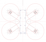
I came up with a design to cut from HDPE using a hole and hacksaw but the precision required was not feasible and the material too heavy and flexible to achieve decent performance. I really did try with this one - cut out two bottom plates spent ages filing / rasping but it was hooooorible.

Screen Shot 2017-01-20 at 12.47.16.png

IMG_5466.jpg

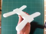
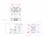
I also tried a development of the versacopter - splicing it with David's mini tricopter frame and using his booms and motor mounts. I called it the boom quad. After a bit of modelling and thinking i quit this for a few reasons. All those tasty swedish carbon booms were getting expensive - the plate designs were looking time consuming to cut, ESC mounting was an issue and also the prop line was ending up adjacent to the top plate and I was worried about clearance / propstrikes to the big ol' go pro up front (this was pre-Session 5/Runcam 3 times...feels like a lifetime right!?).
Screen Shot 2017-04-04 at 14.34.58.png

Screen Shot 2016-06-09 at 17.55.48.png

Screen Shot 2016-06-09 at 17.55.24.png

At this point I took a step back - I looked deeper into the frames i really liked the look of, the ones the youtube guy's fly, the ones that allow for a variety of internal set ups, the ones that are durable / maintainable. Guess what...

Alien 5"
QAV-R
MQC-Fusion
Dronewolf PUP II

The designer in me capitulated to the idea of DIY, even to originality. Maybe just playing with these designs and sucking it up an forking out for CNC carbon would be enough of an adventure, that's before you even get into the components and soldering / mounting / tuning and flying.

So I draw some stuff and some more stuff and go to all the UK CNC Carbon cutters i can find, and... the prices are ridiculous - £150 for a unibody design in 4mm and 1.4mm carbon. So I take a break and consider buying a Martian II.

I don't.

Then I find a CNC place in china on instagram - i send them a drawing of an alien style frame - the price difference is remarkable, but... minimum order is for 10 frames ($120) and a one off prototype is $70 inc. shipping.

Then i stumble across Armattan Productions...give it a shot I think, see what the prices come back like....

Not only are the prices excellent per item (only slightly more than the instagram CNC people) - there is no minimum order - what they are offering is pretty amazing. Sure the website is clunky but it does work. Make an account - upload files - wait for approval (48hrs) - then you can buy it - someone in Taiwan will cut it and send it to you (takes about a month including shipping time). You can make the design public, add a commission, set up a store, potentially make a little money.

If you want.

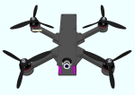
So here's the design. Whilst its not original in design terms and owes everything to the big shot frames out there - I like the look of it, i enjoyed the process and i did kinda do it myself...

Screen Shot 2017-04-04 at 14.46.06.png

225mm motor to motor
4mm arms (16mm wide) - keyed together at centre
2mm bottom plate and arm brace - you can mount the arms underneath or on top of the bottom plate
1.5mm camera plates for a Runcam Swift 2 including angle set screw - braced tight into standoffs to add strength.
1.5mm top plate - flat/clean spot for GoPro mounting
X truss cutouts to lighten top and bottom plates whilst distributing forces into standoffs
35mm standoffs.

Cost of carbon cutting and shipping £32 ($38)

Screen Shot 2017-02-21 at 16.33.45.png

Screen Shot 2017-02-21 at 16.33.30.png

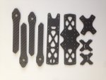
The carbon arrived at the weekend - 89 grams - very smooth cut - i have some components on order - in lots of ways the journey is just beginning and i'm going to need your help...
 
Last edited:

Jugsy

New member
Looking very good! I've got some suggestions, these are a personal preference thing so take em or leave em at your leisure :)
-I've always found a straight X to feel better than wider quads, is there any scope to square this out a bit?
-Some of my favourite features of my current favourite frame (Armattan SCX200) are the mounting solutions. You're definitely on the right track with that camera mount, is it possible you could add some plates or cutouts to reinforce and protect battery leads, antennas etc.? Even just some ziptie holes towards the rear of the frame to mount video antennas is a great start.
-Having individual arms that can be replaced without dismantling the quad is absolutely awesome. Looks like you're on track with this, as long as people build them with good access to the screws :)
-I wonder if you could save some weight removing the front standoffs and adjusting the camera mount so it provides more structural support at the front? This could shed a few grams if you're going after the racing market
 

SheppO

Member
Episode 1

So after a crazy busy week at work/home - I was finally able to grab some kid free space on the kitchen table and make a start on the build. Apologies in advance for the iphone5 photos in less than ideal lighting conditions.

IMG_5586.JPG

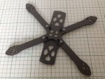
The parts lined up for inspection - very cleanly cut as far as i can see - the edges are were not unduly sharp although i did notice some soreness of fingertips after fiddling about with them for a while. I do not know what grade this carbon is, the weave is fairly large and looks similar to the size used on frames like the Martian II rather than the Alien. The carbon weighed 89g (all pieces)- which seems fine I guess.

IMG_5588.JPG

Edge of the arms - again I have no real way of knowing but the tight laminations look good to me.

IMG_5590.JPG

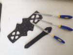
Step 1 - Filing the edges.
My office happens to be in the jewellery quarter of London so I was able to source some cheap diamond files at a supply store there. I really didn't want to do this bit ! Something about hand finishing beautifully
CNC cut edges seemed wrong. He ho. I started off outside with a mask and gloves but switched to working inside in a basin of water. It seemed like the files worked better in the water - i think it stopped them clogging with dust maybe - less messy too.

IMG_5591.jpg

Step 2 - Hardware and Test fitting
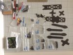
So there ends up being a lot of bit and pieces to put together a frame like this. I separated all the hardware out into labeled bags to make things easier.

IMG_5592.JPG

Here's an exciting moment - test fitting it all together - I used nylon nuts and as few screws as required to quickly lock things down finger tight to get a feel for how the thing will end up. What I was also doing here was testing the idea of mounting the arms above the bottom plate rather than below. This obviously reduces internal space for the PDB/FC stack. Im running the new Lumenier PDB with current sensor - below the RC Explorer F3 board. so - 12mm bolt through the frame into a 6mm nylon standoff. PDB on top of that , another 6mm standoff to lock it down, O rings on there for FC semi-soft mount, the FC on the O rings and nyloc's to finish the whole lot off. I know this is not the lowest profile set up but seems good to leave gaps for wiring and there is still space over the FC for zip tying a VTX.

IMG_5596.JPG

Step 3 - Base frame assembly.
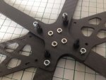
The Alien frame (and others now) use special nuts at the centre of the frame which press themselves into the plate material and hold fast. Chad talks about these nuts a little in the RR Alien Build Vid, he calls them "blind nuts". I did a bit of research and i believe what is used on the Alien frame is more like a "broaching nut". I wasn't planning on bothering with these as they are tricky to get hold of in a small quantity. With a 6mm standoff a 4mm nylock would fit under the PDB. However I did make a call to a UK supplier and was able to have a sample of 5 nuts sent to me free of charge so i went for it. I needed to drill and file out the middle holes of the arm brace to 4.5mm to fit the broaching nuts.

IMG_5595.JPG

I fired up the RR Alien build vid and followed along - substituting my arm brace plate for the Alien PDB. Everything went together super cleanly and seeing those broaching nuts seat themselves in was super satisfying.

That is where we leave it for now...but to close I have a question...

At present I have a good quality 18W soldering iron
http://www.antex.co.uk/soldering/precision-range-soldering-irons/cs18/

Im thinking this will be fine for ESC and FC soldering but I will need something with more power to do the LIPO XT60 connection in particular ? Can I get away with a cheap 40W iron from a DIY store for this or should I be looking at a better quality temp controlled iron to cover all the soldering ?
 

SheppO

Member
Looking very good! I've got some suggestions, these are a personal preference thing so take em or leave em at your leisure :)
-I've always found a straight X to feel better than wider quads, is there any scope to square this out a bit?
-Some of my favourite features of my current favourite frame (Armattan SCX200) are the mounting solutions. You're definitely on the right track with that camera mount, is it possible you could add some plates or cutouts to reinforce and protect battery leads, antennas etc.? Even just some ziptie holes towards the rear of the frame to mount video antennas is a great start.
-Having individual arms that can be replaced without dismantling the quad is absolutely awesome. Looks like you're on track with this, as long as people build them with good access to the screws :)
-I wonder if you could save some weight removing the front standoffs and adjusting the camera mount so it provides more structural support at the front? This could shed a few grams if you're going after the racing market

Dude - thanks for the thoughts and comments -

- yeah a straight X would be pretty easy to do - just a matter of a bit of CAD work and re-submitting to Armattan for approval/costing. It would be interesting to test against the Pythagorean triple 3:4:5 geometry for flight characteristics. Might have props in view though - yuck !

-I have purposely gone for a versatile mounting situation on this design - i.e low tech zip ties and foam strips for the most part. What I do really like however is the 3d printed accessories people are doing for this kind of frame that slide over the rear standoffs and allow the VTX and RX to stack on top of each other. A more specific plate design with provision for mounting is definitely do-able though.

I plan to use the Chad/Steele method of zipties and heatshrink to deal with my antennas for the time being !

-The 1.5mm top plate is pretty flexy so i'd be a bit worried about dropping a set of standoffs. Seeing the way racing frames are going with skinny arms and bottom slung batteries these days - I think of this thing mainly for Acro / fun flying

Cheers
 

SheppO

Member
Ep. 2

So i went for a 50W temp controlled pencil iron that goes to 450 C.

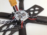
Im using the new Luminere PDB with current sensor. Its designed for a horizontal XT60 connector but i trimmed off the excess tab and used the primary holes for an XT60 pigtail. Soldering this in was a complete pain due to the 12AWG wire but i managed it in the end - hope I didn't fry any components on the board.

Motor leads trimmed, soldered to ESCs. Heat shrink slipped on and wires routed to PDB and soldered up. Ended up being a bit of fiddle to do it neatly.

IMG_5635.JPG

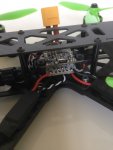
ESC signal and ground routed under the PDB ready to hook up to the FC

IMG_5636.JPG
 

SheppO

Member
FC Power

Now I'm a bit stuck. I have the Luminere PDB and the RCExplorer F3FC.

Screen Shot 2017-04-25 at 14.30.42.png

Im clear on taking the current sensor wire over from the PDB to the Isense pad on the FC.
VCC on the PDB needs to go to the main battery input on the FC which is also the Vbat.

But how then is the best way to power the board ? David takes 6V from the baby PDB into the BEC input pads to give better power for a tricopter servo on the dedicated edge pad but this isn't needed for me.

The board seemingly will not power off the BEC input pads alone - which suggests that David was actually powering his board at VCC level through the main bat/Vbat pad.

Litterbug helped me out on this over on the RCEXp forum but I'm still super confused - i would really like to avoid moving that tiiiiiny surface mount resistor if at all poss.

Any help much appreciated

Thanks
 

LitterBug

Techno Nut
Moderator
There should be no need to use the BEC pads on the bottom of the board if you are not running Servos or other voltages > 5v or high current 5V devices. The best way to power this FC is run VBAT directly to the VBAT pin. I prefer to run my power directly to the PDB rather than through the BEC pads on the F3FC too. Makes moving the micro resitor a non issue.

Cheers!
LitterBug
 

SheppO

Member
There should be no need to use the BEC pads on the bottom of the board if you are not running Servos or other voltages > 5v or high current 5V devices. The best way to power this FC is run VBAT directly to the VBAT pin. I prefer to run my power directly to the PDB rather than through the BEC pads on the F3FC too. Makes moving the micro resitor a non issue.

Cheers!
LitterBug

Thanks mate - so all i need to do is hook the small VCC and Gnd pads on the PDB to the main BATT +- pads on the F3FC ?
Does wire gauge matter in this instance ? Ive got 22AWG Silicone from old JST battery pigtails. Otherwise standard servo wire.
 

PsyBorg

Wake up! Time to fly!
Be VERY careful how fast you flip or when you crash. With no grippy stuff there is a HIGH probability you will launch that battery pack. Movement is guaranteed if your straps are not at the very least rubberized.
 

SheppO

Member
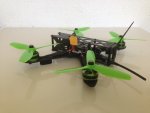
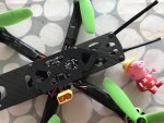
So I ignored psyborg's advice ... as predicted battery ejection into props was the result ! Sliced up the plastic wrap but the cells seem good. The LOS maiden was pretty successful. Flies smooth on totally stock settings - low roll rates I guess and I have no clue how much expo is stock but it was perfectly controllable. Flips and rolls needed a fair bit of space to complete. Anyway - battery pad now done using underside of an old mouse mat ...
 

PsyBorg

Wake up! Time to fly!
Well at least you did not set fire to anything and no wild life was disturbed.

If you want.. take a peak in my Gremlin build thread. Check out the rates I set on it as I use them on all my quads now. VERY soft and controllable in the center range but full on crazy at full deflection if you need.

Set them in your flight controller to compare their curves vs what you use now. If they don't look like what you like just don't save the numbers by changing pages. Most Gui's will revert to existing settings when that is done.
 

SheppO

Member
Well at least you did not set fire to anything and no wild life was disturbed.

If you want.. take a peak in my Gremlin build thread. Check out the rates I set on it as I use them on all my quads now. VERY soft and controllable in the center range but full on crazy at full deflection if you need.

Set them in your flight controller to compare their curves vs what you use now. If they don't look like what you like just don't save the numbers by changing pages. Most Gui's will revert to existing settings when that is done.

Haha - if only you could see the patch of soggy suburban London on which i was flying....

Here is the battery pad - and peppa pig...;-)

IMG_0086.jpg

Will definitely look into your rates etc - thanks buddy.

Im in a bind now -these things are not much fun LOS and I can't justify spending more on this project. FPV kit and goggles are too much of a financial commitment :-(

Looks like I might need to revert to some silly foam planes for a while...
 

PsyBorg

Wake up! Time to fly!
I would say keep this. LOS can be very fun as well as an awesome way to build skill and muscle memory. I fly LOS a lot to test pids or to see where in one of my tricks I go wrong repeatedly. I been flying the Gremlin more LOS then FPV as I seem to have an issue keeping a working camera on it.