1806 pwer pod mount

danskis

Master member
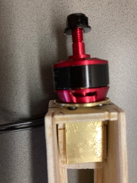
I really don't like working with the small 1806 and 2206 motors because they can be difficult to mount. So I start thinking about a flite test power pod to make accessing the screws on the back of the motor more accessible. This is what I came up with for my new motor glider. Its just a round piece of brass drilled to accept the motor with a tab soldered on the back (Weller soldering gun, silver solder). The tab goes through the firewall and will be screwed with one screw to a block of wood inside the fuse (still working on that). Remove the screw and the "pod" comes out. It would be great if someone would start printing these.
1806MotrMount.jpg

1806MtrMount.jpg
 

danskis

Master member
I was just looking at the picture again. Wouldn't it be great if, instead of a screw to hold the pod in, there was a spring loaded rod that held it in and all you had to do was pull on a tab and pull the pod out. Maybe I'll just drop a rod in through the hole in the tab from the top of the fuselage.
 

BlockerAviation

Legendary member
I really don't like working with the small 1806 and 2206 motors because they can be difficult to mount. So I start thinking about a flite test power pod to make accessing the screws on the back of the motor more accessible. This is what I came up with for my new motor glider. Its just a round piece of brass drilled to accept the motor with a tab soldered on the back (Weller soldering gun, silver solder). The tab goes through the firewall and will be screwed with one screw to a block of wood inside the fuse (still working on that). Remove the screw and the "pod" comes out. It would be great if someone would start printing these. View attachment 201363
View attachment 201364
I was just looking at the picture again. Wouldn't it be great if, instead of a screw to hold the pod in, there was a spring loaded rod that held it in and all you had to do was pull on a tab and pull the pod out. Maybe I'll just drop a rod in through the hole in the tab from the top of the fuselage.
Never thought of that! I have some aluminum and aluminum solder that are just collecting dust so I may give it a try.
 

Turbojoe

Elite member
The brass will be great for proof of concept but it's gonna add a whole bunch of weight. I have my 3D printer set up but that's about all I've unpacked so far. (Still dealing with health issues). I have some of the 1806 motors I got from Doug that are in who knows what box. If I ever find one so I can get exact measurements I may try to print up something like this. In the meantime the micro Cox 3D printed mounts that Doug sells look and work amazingly well and weigh almost nothing. LINK

Joe
 

rockyboy

Skill Collector
Mentor
I was just looking at the picture again. Wouldn't it be great if, instead of a screw to hold the pod in, there was a spring loaded rod that held it in and all you had to do was pull on a tab and pull the pod out. Maybe I'll just drop a rod in through the hole in the tab from the top of the fuselage.

Spring loaded rod works great for these motor trays. I did this on my GeeBee Dreamer biplane - that part of the build starts here https://forum.flitetest.com/index.php?threads/gee-bee-dreamer-bipe.57753/#post-462651

I'm also doing this for my Paper Tiger build - here's the motor/battery/esc tray. Built from a very thin plywood tray and thicker plywood firewall & epoxied bracing. That blob of spackle on the front is over a carved foam block I'm using to make the fiberglass cowl mold. Note the hole in the tray near my finger for the spring loaded pin to drop into. The epoxy around the hole makes it stronger, but mostly it covered in my first miss-aligned hole that didn't engage with the pin properly. Second try drilling the hole worked much better.

PXL_20210608_172959753_copy_1024x768.jpg


Here's a close up of the spring loaded latch - this plane is big enough I'm using a standard du-bro hatch latch, screwed & epoxied to a plywood brace and then the balsa fuselage. For an 1806 sized plane I'd probably try to bend up a latch using a pen spring and use CA hardened balsa bracing instead of this heavy setup.
PXL_20210608_173022322_copy_1024x768.jpg


And the down the barrel view showing how the pin is situated to the rails.
PXL_20210608_173006704_copy_1024x768.jpg


The really awesome thing about using this setup is not needing to build a battery hatch somewhere else into the design. Time to change battery - just pop the spring loaded pin up and slide out the whole front of the plane. Then I can install the new battery without my fumble fingers causing damage to the airframe - very important for winter time flying for me. Only one long extension wire needed to get from the ESC to the receiver too - the rest of the power wires stay with the tray.
 
Last edited:
very interesting!
I personally like to just put a bunch of glue on the fire wall and be done with it!
I know that's not the best way but it works for me.
I like that idea though ill have to try it sometime!
 

danskis

Master member
@rockyboy - rails!!!!! what a great idea - it will be on the next one. Again this whole thing is to avoid screwing those tiny m3 screws for the 1806 motor through the back of the firewall.
 

Turbojoe

Elite member
The rail mounts are perfect. I'm working on a 3D printed part based on your design. My part includes 2 degree down and 2 degree right thrust built in. It also includes a screw slow slot that allows you to change right or left thrust angles that will require a screw instead of a spring loaded part. Down thrust adjustment is very easily included in the .STL files if asked for. I just can't find my motors to verify motor screw hole positions. If I get it all straightened out I'll post the file to Thingiverse and here as well for those interested for free. Don't hold your breath though. It could take a while before I can make usable files available unless I get engineering files showing me the motor screw hole locations. I'll definitely need YOUR fuselage width and preferred length of "tab" that extends into the fuselage rails.

Joe
 

Turbojoe

Elite member
Thanks dude! Dopey me didn't bother searching Google like I should have. I still haven't found my motors yet. I'll try making any changes necessary to the file I cobbled together.

Do you have or do you have a friend that has a 3D printer that can print the .STL file for you? I'd be happy to make any changes to the file that you find are needed. You came up with the idea so Thingiverse will show you as the designer when I post a working final version. I can't do much more than sit anymore so working on goodies like this is pure heaven to me.

I know what you want and will do what I can for you but still, the 3D printed Cox mounts are perfection. They look amazing and fit with no mods. Dirt cheap too. Just a thought......

Joe
 

Turbojoe

Elite member
OK so I don't remember. Isn't the motor body threaded for the mounting screws? 2mm or 3mm? I'll have to make the mounting base extra thick with recesses for the screws to the motor. Button head screws preferred but I can make it deep enough for socket head screws too.

Joe
 

Turbojoe

Elite member
Tell me how deep and wide you'd like the flat part of the mounting plate that slips into the fuselage past the firewall in MM preferably. A spring mount for that plate just isn't going to be secure enough. I'll be incorporating a screw slot that will allow left/right thrust line adjustment.

Joe
 

danskis

Master member
The willynillies are great motor mounts but this is supposed to be a high performance glider. I didn't want to increase the frontal area any more than I had to. This is V1.1. I expect to change the nose/motor mount in V1.2.
xrez.jpg xrex1.jpg xrex1.jpg xres2.jpg
 

TooJung2Die

Master member
I've seen plastic bottle caps used as motor mounts for 1806. The caps are round and just the right diameter for the motor.
 

danskis

Master member
@Turbojoe - not much is going to change. I like the current design. I think I'm just going to hack off about 2 inches of the glider nose and move the motor back for better balance. Right now the battery is all the way back and I want to put a bigger/heavier battery in which means that I'd have to add tail weight - always a bad thing in a glider.

So here's the design:

The circle is 20mm in diameter.

The tab can be 20mm across (I'm thinking this can just be cut to fit whatever plane its going in)

The tab is 25mm long (can't wait to see what you come up with for thrust line adjustment)

The mounting holes come off the engineering drawings

Remember there needs to be a 5mm diameter hole in the center for the motor shaft.

Good luck and have fun. I'll get someone here to print one once I get the file.

Dan
 

Turbojoe

Elite member
OK here ya go. Pretty crappy pictures but I'm a pretty crappy photographer.....

The hardest part was working in the slide in plate so it would have enough "meat" in the motor plate. I still haven't found my motors so this is truly a prototype part that may need some adjustments. It should be pretty dang close though. I added 2 degrees down thrust and 2 degrees right thrust. I can change that very easily. I'll attach the .stl file and you can do whatever you want with it. Use Cura or another slicer with setting for the printer that it will be printed on. Let me know if something stands out that you'd like changed before printing. God I love doing stuff like this. I just wish I knew a CAD program other than TinkerCad.

Joe
 

Attachments

  • IMG_20210615_160115.jpg
    IMG_20210615_160115.jpg
    887 KB · Views: 0
  • IMG_20210615_160122.jpg
    IMG_20210615_160122.jpg
    942 KB · Views: 0
  • IMG_20210615_161442.jpg
    IMG_20210615_161442.jpg
    844.2 KB · Views: 0
  • 1806 Slide in mount V1.stl
    374.4 KB · Views: 0

danskis

Master member
Super coooool!!!! I like it. I'm outa town for a while so nothing will happen on my end for a while. The original, I know its hard to see, had the tab going through the center of the circle. Take a look at the very first picture. No big deal I like your's too and can't wait to try it. The only advantage I can think of with my prototype is it might be a little stronger.