36" Northern Pike - 3D Printed Cuda Clone (It Flies & STL's are Posted!)

localfiend

I like 3D printers...
Mentor
Bought one of those little Dart planes from RMRC at Flite Fest Ohio, it's a mini Cuda clone type plane. Flew great for being small, so I thought I'd make it 3D printable and a bit bigger to account for the weight of 3D printed parts.

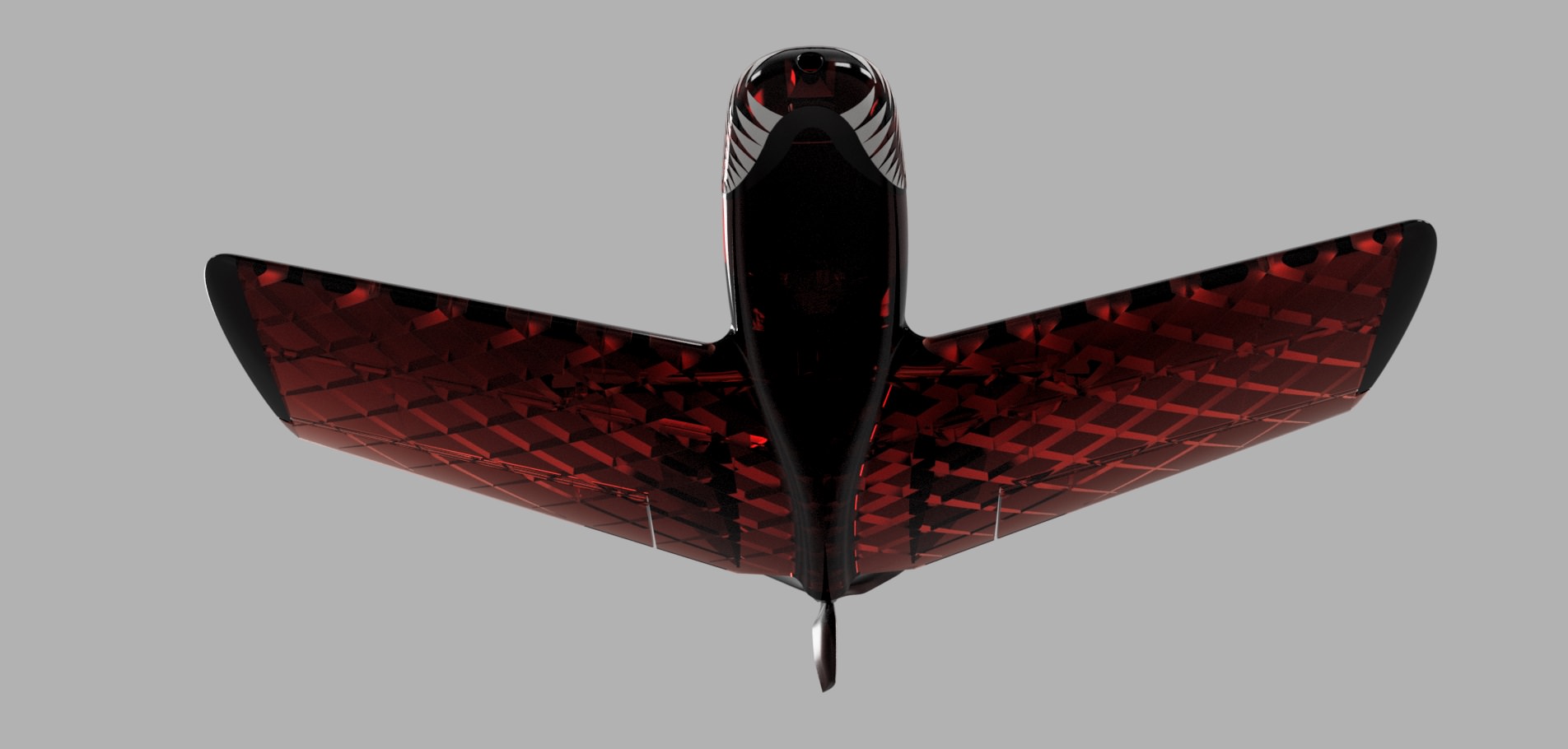
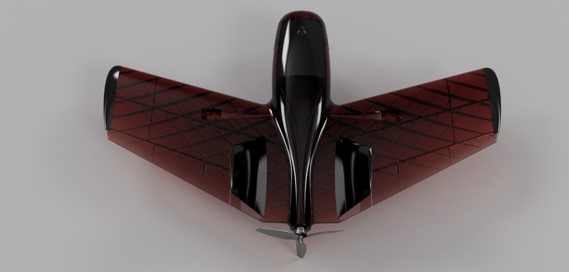
Started drawing stuff up yesterday and here's what I've got.

6MWBbTU.jpg


b6WORyD.jpg


VP3FEyQ.jpg


EOpUpxN.jpg


wvDQVag.jpg


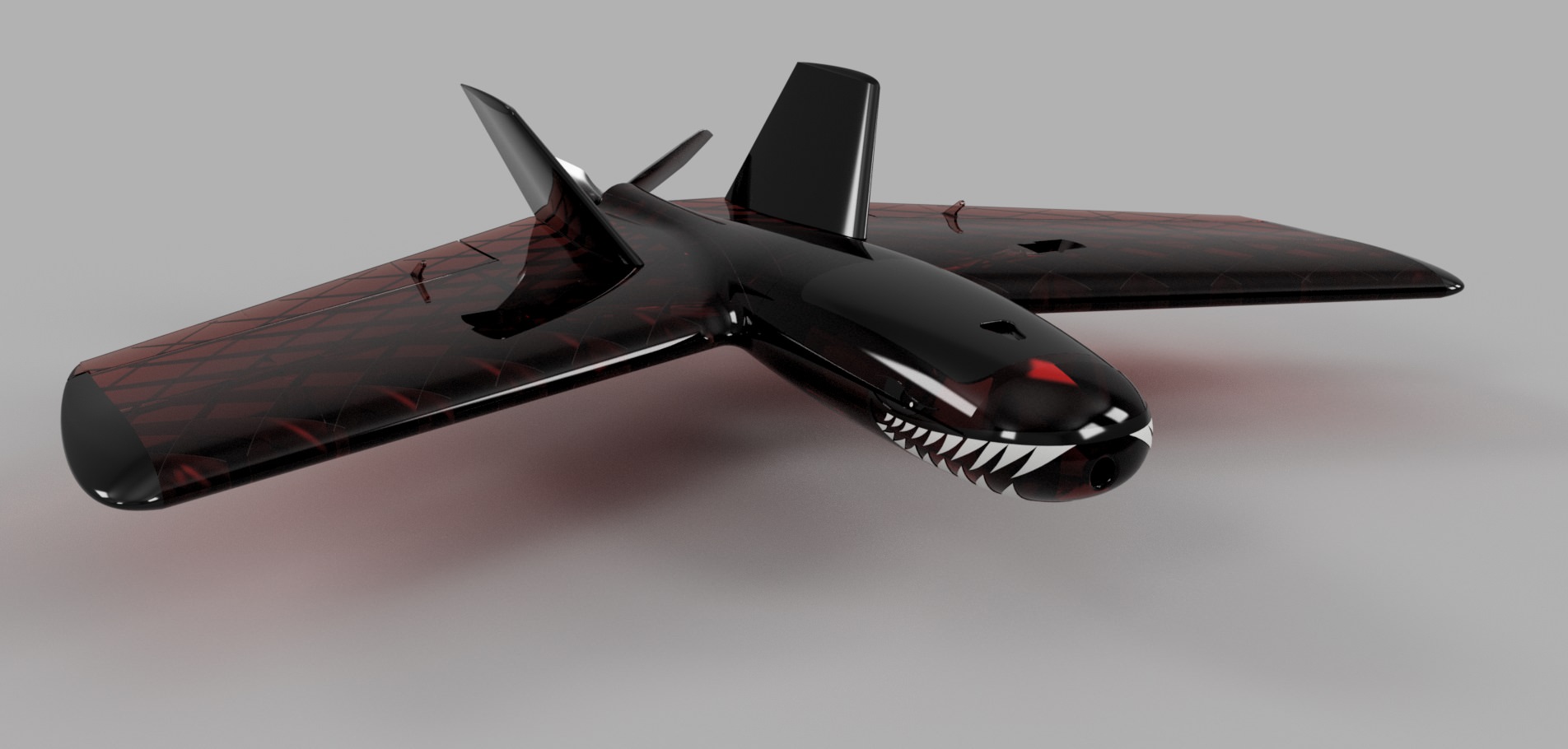
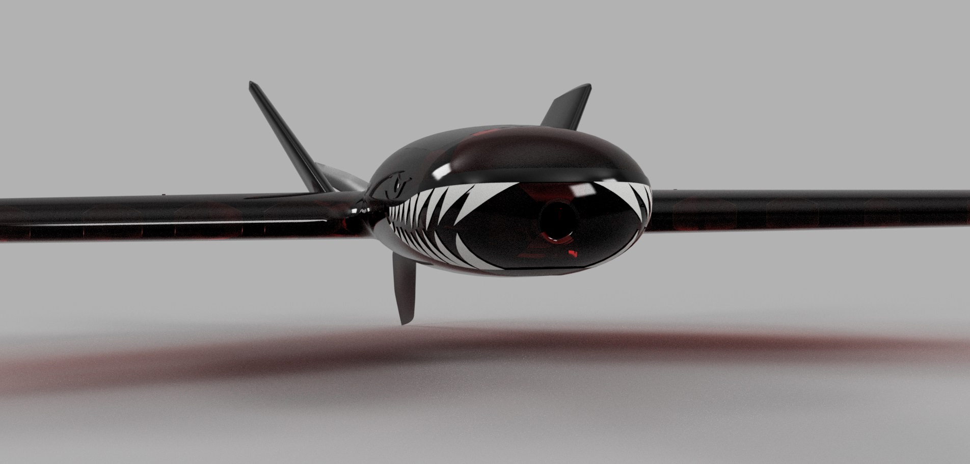
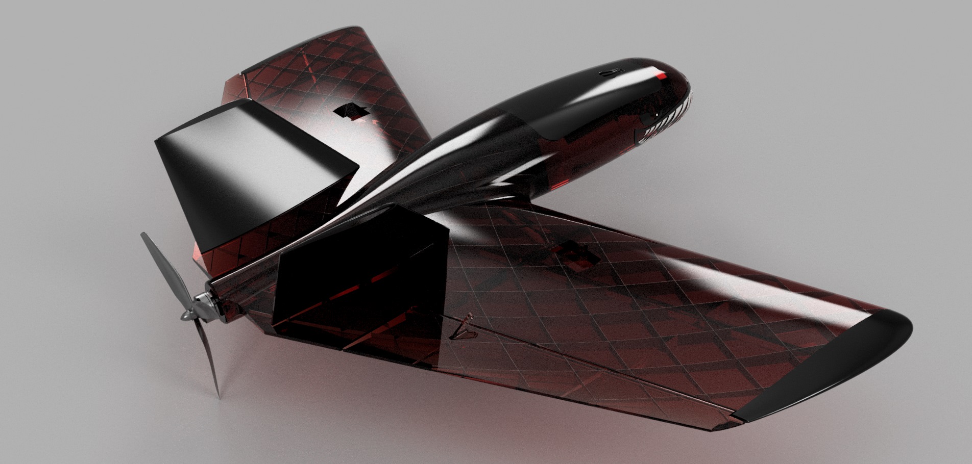
The eyes, mouth, and teeth are all part of the model, and will show up when printing. Should make it very easy to paint, or add some tape or something.

We'll have to see where final weights line up, but I'm hoping to run an F to B pack sized motor on either 3 or 4 s. The nose has been lengthened a good bit from standard cuda configurations to try and make balancing easier. I think a couple 1300mah batts side by side up in the nose will do the job. If not, there's provisions for an FPV camera to add a bit more nose weight. Worst comes to worst, I can always make the nose a bit longer.

The majority of the fiddly bits on the model are done, but I am going to have to set aside something like 5-6 hours to complete the lightening holes in the spars. Hole cutting aside, it's amazing how much easier it is to draw up a simple plane like this compared to a scale aircraft. I'll also be trying out a new cad technique here to try and make the file manageable and not bog down my PC. I'm doing everything possible to get it ready for printing before cutting spar holes. Once all the groundwork is done, I can make each printable section it's own component, and then cut holes. That should hopefully make my life easier from a processor bottleneck standpoint.


************************************************************************************
ETA: Latest Flight is the Maiden of the PETG version.


ETA: It Flies!!


I've posted the files over on Thingiverse for the 36" version. They're free, but if you want to donate something via paypal or tip me on thingiverse I won't say no. :D

https://www.thingiverse.com/thing:3040294

 
Last edited:

Chuppster

Well-known member
I would find it quite entertaining to see a time lapse of you designing stuff like this. Do you think you could do a screen record next time?
 

localfiend

I like 3D printers...
Mentor
Thanks guys. I needed something easy to tackle that I could finish in a short amount of time. I'm really liking how it's turning out so far.

I would find it quite entertaining to see a time lapse of you designing stuff like this. Do you think you could do a screen record next time?

Heh, there's at least 10 hours of solid drawing work into this (a low amount compared to my other projects, but still a long time). I think I would need a new hard drive to record stuff as I went. I've got another even simpler design in the works, and may attempt something like that. My speed gets faster with each plane I make.

I can use Fusion 360's timeline replay feature thing to kind of walk you through the steps I took. It doesn't auto zoom in on what I'm drawing unfortunately. And it may be slightly confusing. I changed the fuselage and spar arrangement, so you'll see some stuff redone after I changed my mind about how I wanted everything to print.

Sorry, no sound. Didn't have time to add a soundtrack. Pick your own and play it. This takes five minutes even at a high rate of speed. :D


Chuppster

Well-known member
Wow, you have a lot more experience in CAD than I do. I can do extrudes and sweeps but I struggle with the body molding and whatnot.

How did you build those matrices for the inner structural supports?
 

localfiend

I like 3D printers...
Mentor
Wow, you have a lot more experience in CAD than I do. I can do extrudes and sweeps but I struggle with the body molding and whatnot.

How did you build those matrices for the inner structural supports?

I tend to stay away from sculpting and molding. I'm bad at art and freehand drawing, and it can be even more difficult when fractions of a millimeter matter for 3D printing. I try and stick to traditional methods like you mentioned. Extruding, sweeps, and lofts from 2D sketches. All the curved bits on this plane are from lofts. If you haven't played with that tool, you'll really want to take a look at it. Just loft bodies between sketches. You can mix and match shapes, add guide rails etc..
loft.jpg


As for the spars. They're a simple extrude. Because you have to fool current generation slicers to get thin wall prints (single perimeter), the spars are their own solid body, contained inside the solid body of the wing. They are not connected. In fact, the outer surface of the wing needs to be about .8mm away from all internal structure support.

My process is to draw the wing/fuse/tail/vstab etc, then extrude some spars through it. I then use the offset face tool in the patch workspace to make a surface identical to the outer surface of the wing, just .8mm smaller. I can then use that new surface to slice off the extra spar material that sticks out of the wing.

Here's the vertical stabilizer with some extruded spars.

Spars.jpg


Here's an offset surface of the vertical stabilizer highlighted in blue (it's .8mm smaller than the vstab).

Spars2.jpg


Here's the selected leftover bits of the spar after using the split body tool in conjunction with that offset surface.

Spars3.jpg


And the excess deleted. Do that for all sides, and spar pieces and you'll be left with a solid spar body, contained inside the solid body of your airplane part. Oh, forgot to mention, the spars are all .1mm wide. That will give you the lightest possible spar structure your printer can handle while still being strong. Also, the spar distance from each other is around 45mm. If you leave gaps much bigger than that, the outer surface of your plane can start to sag.

Spars4.jpg


And finally, you'll want to lighten those spars. This method is way too heavy without removing a good bit of material. I've found that a good rule of thumb, is to use the largest size circles that will fit, and don't ever make a hole in a spar smaller than 3mm. If you go much smaller than 3mm, the spars become to brittle.

Again, I just make sketches, and extrude holes through the spars.

Spar Holes.jpg
 
Last edited:

Chuppster

Well-known member
Thanks for the guide! It's really helpful, and if I ever muster up the gumption to actually design one of these I may ask questions. I've used the sweep tool before but not like you did, with the rounded features. It looks really good!
 

localfiend

I like 3D printers...
Mentor
Should we be anticipating a flight video anytime soon?

I sure hope so. Everything is now done except for lightening holes in the spars, as only the V-Stabs are all ready to go on that front. Control surfaces are all setup, wire runs are good, additional carbon arrow spar holes are ready if needed. Firewall is all setup to take the same pods as my Flapjack design. Hatch is ready. Actually, need to add some indentations for magnets. Oh, and finalize the CG estimate and add it to the model.

3D Printed Northern Pike Sketch2.png

3D Printed Northern Pike Sketch.png


If stuff lightens up like I'm hoping after I cut holes, the plane should take around 700 grams of filament to print.
 

localfiend

I like 3D printers...
Mentor
I didn't see anything referencing how big this is. What is the wingspan?

Oops. It'l be 36 inches. So, just an inch wider than the bigger Cuda. It will however, be slightly heavier. I think the balsa cuda's all up weight is just a bit over 900 grams. All up weight of this plane will probably be over 1000. Wing cube loading will probably be something like 9. Not lightweight, but not terrible, especially when you consider the advantages of a forward swept wing. I'm hoping it will be moderately fast.

ETA: I thought i mentioned the size somewhere, turns out it was in the thread title. I didn't actually forget to mention it lol.
 
Last edited:

localfiend

I like 3D printers...
Mentor
Well, after 5 hours of work, I got lightening holes into 5 of the 7 wing sections. Took me longer than I was remembering. Probably because I made the spars a bit more dense on this plane than normal. I want the wings to stay stiff, forward sweep is not something you want to flex.

3D Printed Northern Pike v7.png


At least I've got enough to fill up a build plate. Got the completed sections for the left and right wings printing on two different printers right now.

PikeWingSections.jpg


I'll start tackling the rest of the parts tomorrow evening.
 

FAI-F1D

Free Flight Indoorist
Very cool. I'd love to build one of these, but at more like 24" span. Any possibility a smaller one?
 

localfiend

I like 3D printers...
Mentor
Very cool. I'd love to build one of these, but at more like 24" span. Any possibility a smaller one?

That depends, you willing to get your hands dirty? :D

There are a couple issues with directly scaling down models designed like this. The primary issue being that it's drawn in CAD to work with a .4mm nozzle. We're forced to do this with current generation slicers, as the only way to get thin wall prints that are strong enough for aircraft, is to trick the slicer by making a specifically broken stl file.

If you were to reduce the model stl size in your slicer, the output would have a ton of errors. Basically you'd end up with holes in the outer skin, and in the spars. It would be a mess and would be unsuitable for flight. So, straight shrinking of the model won't work, without completely redrawing all the internal structure in CAD (the most time consuming part).

There is a method to get around this issue. If you scale the 3D printer nozzle size down at the same percentage you shrink the plane stl files, it will still work. The good news is that it will also drastically lower the weight required, as the thickness of the outer skin goes down. Also, 3d printer nozzles are cheap, and swapping them around only takes a few minutes. If you went this route, and dropped the size of the plane by 25% and reduced the nozzle from .4mm to .3mm things would probably work (servo hole size might have to be adjusted, but I can do that). You'd end up with a 27 inch wingspan.

I'm not sure what wing loading would be though. I will be able to give a better answer after the entire plane is done. When that happens, I can scale stuff down, and calculate out what total weights will be. If they're still on the high side, we should be able to come up with a different lighter spar arrangement at that size.

If the spar arrangement has to be changed, that's where you might have to get your hands dirty. I'll draw up the spars, and get the rest of the plane figured out if you'd be willing to do some CAD grunt work and punch lightening holes in all the spars. It's not a difficult or complex process, and I can walk you through it. It's just tedious. Expect about 6-7 hours of drawing circles and ellipses.