

AeroForge3D
New member
Hi all, this is AeroForge3D. We design 3D printable RC planes. This is our own product, and we sell the files (link at the bottom). We also wanted to share the CG work and print notes, because they apply to most printed sport planes. We are still learning a lot, and we welcome feedback.
Flight clip:
The plane
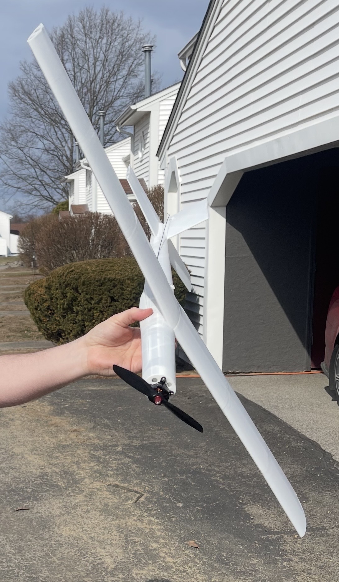
- 900 mm span, 645 mm long, wing cube loading about 11.2
- Intermediate sport plane, not a trainer and not a 3D plane. It has flown (clip above). Fast, quiet, and fine in 5+ mph wind.
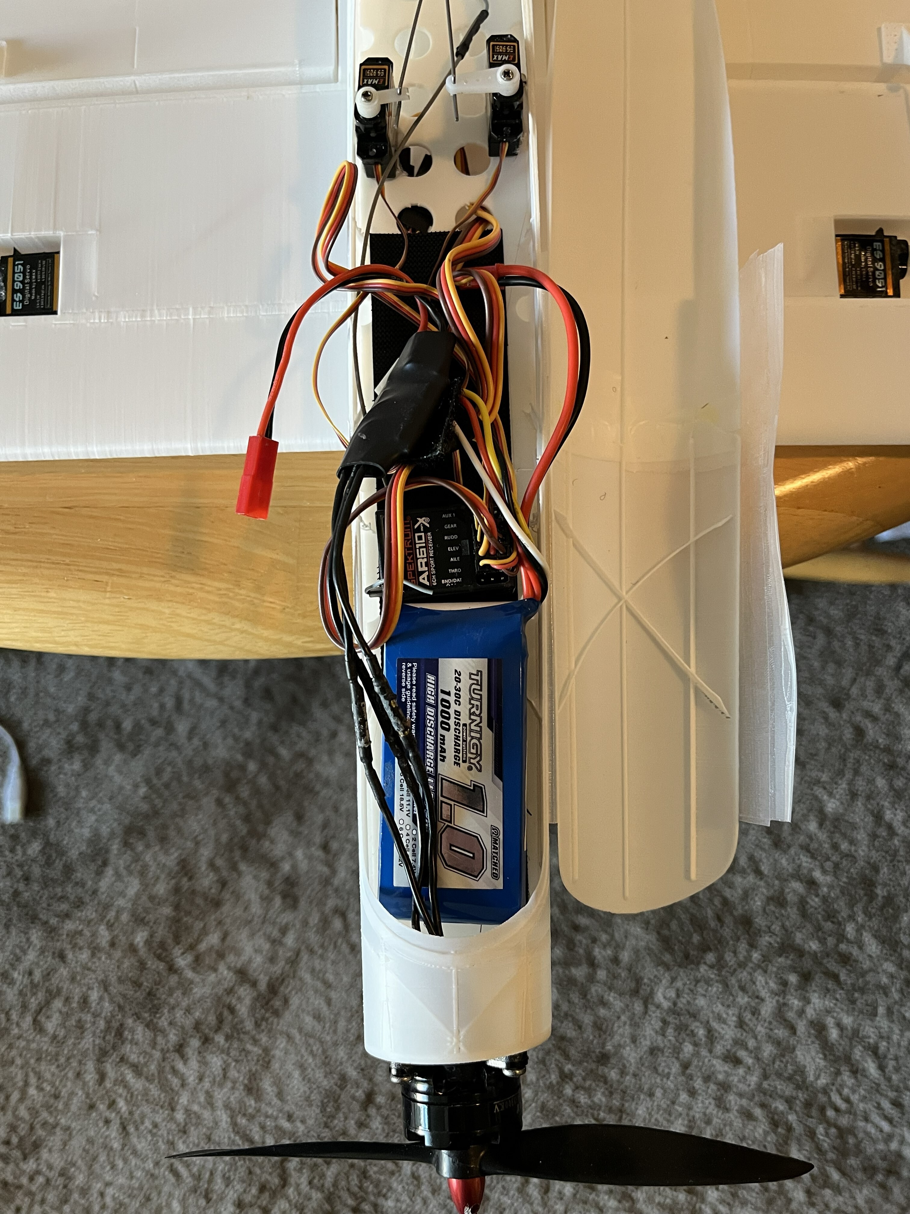
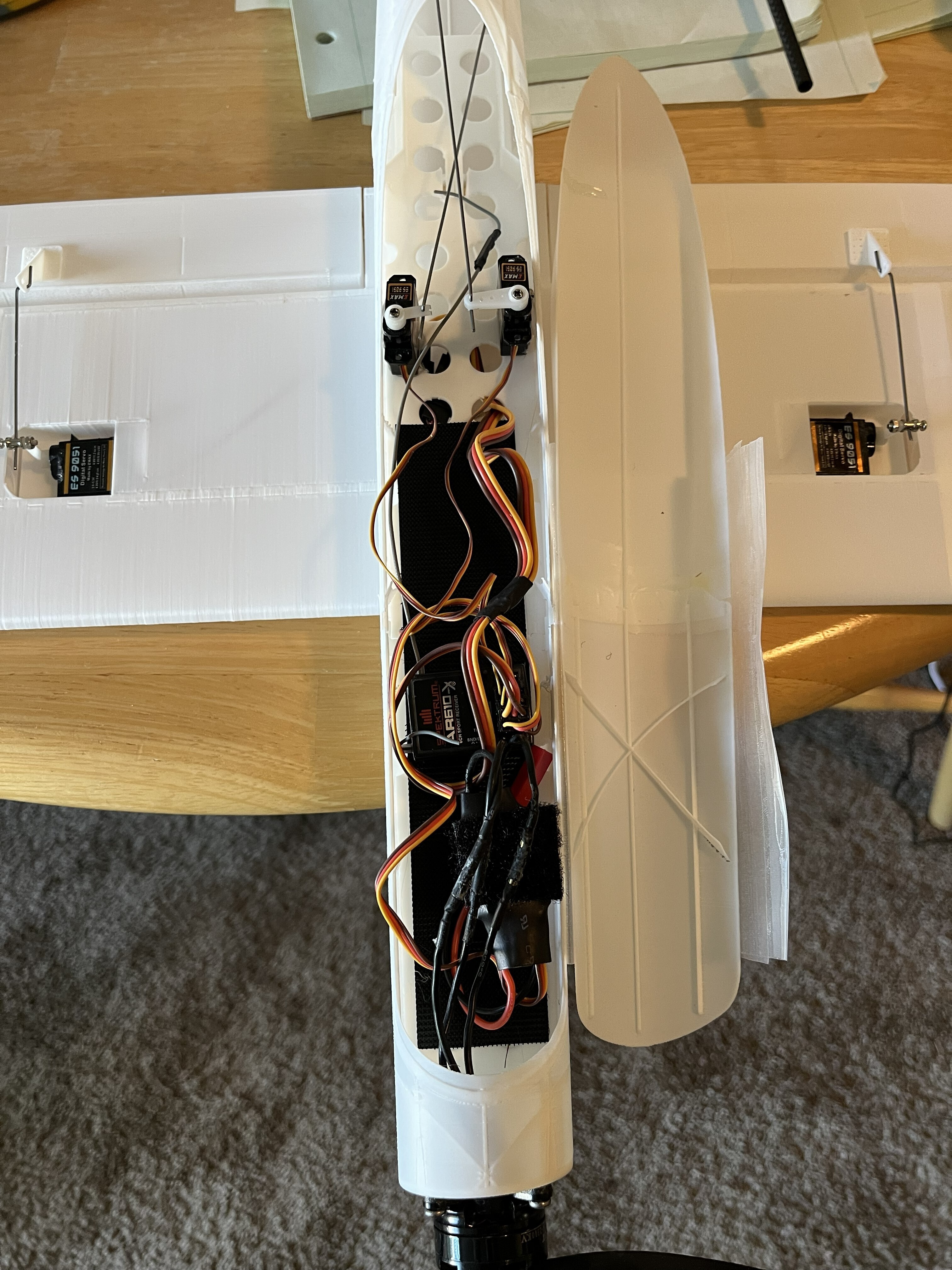
- Recommended setup: Radial 1806 2280 kV motor, 20 to 25 A ESC, four 5 g micro servos, 1000 mAh 3S LiPo, 6 x 4 prop, 1 mm wire pushrods
Where the CG goes, and why we give a band instead of a mark
- AVL (vortex lattice) puts the neutral point 230 to 232 mm aft of the spinner tip (230.1 with the fuselage modeled, 232.4 without).
- USAF Digital DATCOM puts it at about 213.5 mm. Its methods come mostly from full size aircraft data, and this wing runs at about Re 1.7 x 10^5, so we treat DATCOM as a pessimistic bound.
- First flight CG: 39 to 46 mm behind the wing leading edge, which is 210 to 217 mm from the spinner tip. Measure at the wing root with the plane level. Start at 42 mm. Never go aft of 51 mm (222 mm from the spinner tip).
- Why start there: only 210 to 213 mm is ahead of the DATCOM number.
- The vertical tail volume is modest (0.027 exposed). If it feels pitchy, move the CG forward before you touch the tail, and don't shrink the fin.
Print notes
- 0.16 mm layers, 15% infill, no supports, parts printed flat on the plate. PLA or LW-PLA.
- About 16 hours and about 325 g of filament.
- If you slice it yourself instead of using the Bambu Lab example project, turn on thin wall detection with the Arachne wall generator.
- Expect some knife cleanup on the joins. We use super glue gel plus hobby tape on the joints, and low temp hot glue for the control horns (go easy so the PLA does not warp).
Question for you: if you have compared AVL, XFLR5 or an online CG calculator against where your own printed plane actually balanced well, how far apart were they?
We will answer questions here.
Files: https://www.printables.com/model/1895562-sport-flyer-v1-3d-printed-rc-plane-900-mm-sport-ae
Flight clip:
The plane
- 900 mm span, 645 mm long, wing cube loading about 11.2
- Intermediate sport plane, not a trainer and not a 3D plane. It has flown (clip above). Fast, quiet, and fine in 5+ mph wind.
- Recommended setup: Radial 1806 2280 kV motor, 20 to 25 A ESC, four 5 g micro servos, 1000 mAh 3S LiPo, 6 x 4 prop, 1 mm wire pushrods
Where the CG goes, and why we give a band instead of a mark
- AVL (vortex lattice) puts the neutral point 230 to 232 mm aft of the spinner tip (230.1 with the fuselage modeled, 232.4 without).
- USAF Digital DATCOM puts it at about 213.5 mm. Its methods come mostly from full size aircraft data, and this wing runs at about Re 1.7 x 10^5, so we treat DATCOM as a pessimistic bound.
- First flight CG: 39 to 46 mm behind the wing leading edge, which is 210 to 217 mm from the spinner tip. Measure at the wing root with the plane level. Start at 42 mm. Never go aft of 51 mm (222 mm from the spinner tip).
- Why start there: only 210 to 213 mm is ahead of the DATCOM number.
- The vertical tail volume is modest (0.027 exposed). If it feels pitchy, move the CG forward before you touch the tail, and don't shrink the fin.
Print notes
- 0.16 mm layers, 15% infill, no supports, parts printed flat on the plate. PLA or LW-PLA.
- About 16 hours and about 325 g of filament.
- If you slice it yourself instead of using the Bambu Lab example project, turn on thin wall detection with the Arachne wall generator.
- Expect some knife cleanup on the joins. We use super glue gel plus hobby tape on the joints, and low temp hot glue for the control horns (go easy so the PLA does not warp).
Question for you: if you have compared AVL, XFLR5 or an online CG calculator against where your own printed plane actually balanced well, how far apart were they?
We will answer questions here.
Files: https://www.printables.com/model/1895562-sport-flyer-v1-3d-printed-rc-plane-900-mm-sport-ae


