An usual fighter plane.

quorneng

Master member
P13aKit.jpg

It has been done before as an EDF but from what I can tell some sort of scale sacrifice had to be made with EDF installation and/or the wing section.
My intention is to keep to true scale including the inlet and exhaust by using extreme light weight materials . The exhaust is actually a slot far from ideal for an EDF.
The original was intended to be a coal fired ram jet but only a full scale glider was completed by students under the direction of Lippisch immediately after the was and was promptly 'acquired' by the US and taken to the USA along with Lippisch. NACA tested the glider in their full size wind tunnel but showed its low speed characteristics to be poor, although previous war time tests in Germany on a small model indicated it was stable in a super sonic wind tunnel.
Lippisch as a well respected aeronautical engineer advised Convair on the XF82 delta interceptor but the Convair design team disagreed with Lippisch and selected a thin delta wing rather than the thick one of the P13a.

My first task is to design and make the EDF duct. It will be printed in LW-PLA
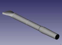
FullDuct.jpg
It looks impossible long and narrow let alone the effect of the slot exhaust.
The complete printed duct with a 50 mm EDF doesn't look any better!
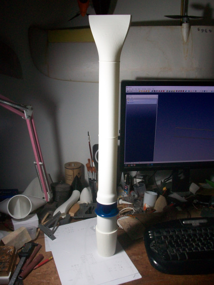
FullDuct (2).JPG

Testing showed the end of the slot tended to vibrate.
You can hear the 'drone' on this video so it required extra stiffening.
I fear this is not going to be easy, let alone fly properly.
 

quorneng

Master member
The fuselage is a 'half shell' built over the plan. Formers and a planked skin all in 3 mm Depron.
The formers have appropriate half circle cut outs so once the half shell is lifted from the plan the duct can be fitted.
DuctFit1.JPG

Depron is easy to sand so the cut outs can be 'adjusted' so the duct sits exactly half way into the fuselage shell. It is then be glued in place.
The EDF and the inlet duct are next.
EDFinlet.JPG

Once the glue is dry the full length duct greatly increases the rigidity of the half shell.
The next task is to add the other half of the formers.
RHformers.JPG

Note the EDF 'magnet wire' motor leads passing through the formers. For the same current capacity magnet wire is about half the weight of conventional flexible silicone coated wire.
Then the remainder of the fuselage is planked.
BodyCmplt.JPG

Note the base of huge fat fin is left off to allow the installation of the rest of the electrics in due coarse.
The wings are next.

.
 

quorneng

Master member
Actually I am using Technicqll polyvinyl adhesive. Very like POR but in 24 hours it sets rock hard so it can be effectively sanded.
After the long duct the delta wings are the next daft bit. A crazy blunt nosed very thick section. The underside is flat where as the top surface has a modest reflex towards the trailing edge. Top and bottom skin are a single piece. No ribs just two 3 mm Depron shear webs. the biggest pain is the Depron cannot be formed to make the leading edge so it had to be planked. The only good bit is the wing once complete is so thick it can be simply glued directly onto the fuselage.
RHwing1.JPG

The elevon is made up separately.
Note the ESC is now installed with external 'finger' finning.
The EDF exhaust slot is smaller than scale but when it is all painted black should be hidden.
FullSlot.JPG

Both wings glued on.
L&RhWing.JPG

All very compact but my confidence that such a shape will be aerodynamically controllable is questionable to say the least.
Still quite a bit to do.
 

quorneng

Master member
The fin/cockpit is built like the wings, Depron skin over Depron formers.
FinOn1.JPG

The canopy cut out gives access to the battery.
BattBox.JPG

Note the Lemon stab Rx. I suspect this plane will need plenty of stability help.
To help visibility the control surfaces are black as is the exhaust 'slot'
BlackSurfaces.JPG

The Lippisch has a substantial skid under the nose.
BlackSkid.JPG

Just as well as it hopefully will prevent the duct inlet becoming a plough! It also gives a hand hold for launching.
With a 1500mAh 3s 35c it weighs a reasonable 386g with about 300g of thrust.
The CofG position is a bit of a guess. We shall see.
Just have to wait for some seriously calm weather. Turbulence I don't need!
 

quorneng

Master member
The first flight proved to be rather short although it did fly with what appeared adequate thrust but control was very marginal with the result it flew into a steel pole.
RugyPole.JPG

Fortunately the EDF duct is undamaged so the repair is largely just a case of simply gluing the bits of skin back in place! :unsure:
I now have to decide if the lack of control is 'feature' of the aerodynamics or whether moving the CoFG forward would help and then by how much?
I never expected it to be easy. ;)
.
 

Piotrsko

Master member
I believe that low speed mostly unstable flight is a "feature" of low aspect ratio delta planforms. History is full of related examples particularly at Muroc AFB ( nee Edwards). More if you include circular or other odd wing designs.

Cant help with CG placement, above my pay grade by a factor of several. Although I am a bit suprised that you managed to hit a pole.
 

dap35

Elite member
There are a number of on-line CG calculators, here are a couple:
 

quorneng

Master member
dap35
No problem with the calculators but will they still work with a delta that has such an extraordinary wing section? Made worse by the fact that such a delta is likely to have a very critical CofG anyway including the effect of any control surface reflex for stability..
I fear it will be a case of adjust, crash, repeat and hope a reasonable flight can be achieved before it gets beyond repair.
The 'pole' damage is now repaired.
RugbyRepair2.JPG

Just need some calm weather.
 

dap35

Elite member
dap35
No problem with the calculators but will they still work with a delta that has such an extraordinary wing section? Made worse by the fact that such a delta is likely to have a very critical CofG anyway including the effect of any control surface reflex for stability..
I fear it will be a case of adjust, crash, repeat and hope a reasonable flight can be achieved before it gets beyond repair.
The 'pole' damage is now repaired.
View attachment 237442
Just need some calm weather.
Glad the damage is repaired!
I would say use the calculator. I have used them on both flying wings and deltas and it is way better than just guessing :cool:
 

quorneng

Master member
Moved the battery forward by about 10 mm and tried again.
Better, it actually flew, but remained very difficult to control resulting in s rather heavy 'nose down' landing.
DamageNose.JPG

The damage was quite extensive and this time the duct suffered as well.
DamageDuct.JPG

There would be no alternative but to fully extract the duct and print the required replacement parts.

DuctExtract.JPG

The repaired duct in place.
NewDuct2.JPG

Somewhere along the line the RH servo stripped a gear so that had to be replaced too
At the same time I moved the battery another 15 mm further forward which is about as far forward as it can go and stay within the leading edge of the fin.
All repaired again.
Repaired.JPG

Just need some suitable calm weather
.