Power_Broker

Active member
Random update: I'm thinking about taking the on-board LiDAR sensor and turning it into a scanning LiDAR system as a sort of SLAM (Simultaneous Localization and Mapping) terrain mapping unit.

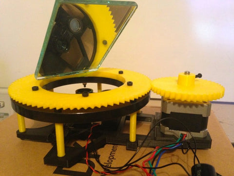
Basically the lidar sensor will be mounted in the fuselage pointing towards the nose of the plane instead of directly at the ground (as it is now). Then I spin a tilted mirror with a small DC motor in front of the LiDAR sensor. I also want to stabilize the entire unit with the on-board IMU and a couple of extra servos.

With the correct mirror angle, mirror rotation speed, and LiDAR sample speed, I'll be able to map the ground below the plane for around $200. If you were to buy a COTS unit that did this, you'd probably pay AT LEAST $450. :eek:

Still thinking about this feature and am not working on it yet, just wanted to let y'all know what's in the works "long term"
 

Power_Broker

Active member
Here's an example of someone else's attempt to make a homemade LiDAR scanner system:
Lidar-LIte-360_large.jpg


If I finish mine for the plane, it'll be a lot smaller and lighter, lol
 

Power_Broker

Active member
I know it's been a while since I've posted here, but I'm still working on this project!

Lately I've been waiting for good weather on a free weekend to conduct test flights AND a ton of work on streamlining my "War Thunder"-based Processor in the Loop Simulator (PiLSim) design. This PiLSim will help me debug and develop flight controllers to use on they RC plane.

This PiLSim will consist of my Arduino-based hand controller and the airplane simulator PC game "War Thunder". When flying in "War Thunder", the game will provide "fake" flight sensor telemetry that is gathered by a Python script (running on my machine) and sent to the Arduino in the hand controller as feedback. The feedback is then processed by the developmental flight control software (autopilot) and the resulting controller output is then sent back to the game as HID joystick commands.

The Python script that will make all of this happen is called Thunder Viewer and is currently in open Beta testing.

In case anybody here plays "War Thunder", you can use Thunder Viewer to record your match data, stream it to the application Tacview, stream it to friends, and stream it to a USB device (i.e. an Arduino). Here is a functional diagram of all it can do:

Thunder_Viewer_Functional_Diagram.png


And here is an example of the GUI:

71610000-42be2f80-2b5b-11ea-8781-61b8a3f04bfc.png
 

Power_Broker

Active member
To make the PiLSim design more clear, here's a functional diagram that explains how it all the pieces work together:

pilsim.PNG


I did some testing last night and already fixed some bugs that would've caused my plane to crash if I did the tests "live"!

Still have more work to do...
 

Power_Broker

Active member
If you want to download Thunder Viewer without having to install Python, you can download the EXE file and run it directly. To get the latest version, check out the latest release from the GitHub page and download "Thunder_Viewer.zip". The exe will be in that zip.

If you want to directly download the exe of the current version (as of today), click here.
 

Pendularknot130

New member
Update #4.)

Finished designing and implementing the motor mount (.obj file attached):

View attachment 128786
View attachment 128787
View attachment 128788 View attachment 128789
View attachment 128790
View attachment 128791


I also finished the wiring for the hand controller. The biggest thing I had to do was cut the wires to the joysticks and solder on dupont servo connectors to them so I could plug the joysticks into my Arduino PCB. Also note that I have bluetooth implemented on the hand controller. This will allow the hand controller to communicate with the testing laptop (i.e. datalogging telemetry) wirelessly.

Here are some pics of the original joystick connectors (note the pin labeling on the one side of the connector:
View attachment 128780
View attachment 128781


This is one of my joysticks after soldering on the dupont servo connectors:
View attachment 128782


I realized during testing that I needed to supply 3.3V to the joysticks so that I didn't damage the Arduino. If i powered the joysticks at 5V and set the joystick position within a certain range, the output voltage of the joystick will go above 3.3V and damage the Arduino. To work around this problem, I cut the red wires on the dupont servo connectors, soldered them all to a single red wire, and connected it to the 3V3 pin on the PCB. With the joysticks powered properly, there is no chance the user can damage the arduino via the joysticks.

View attachment 128785
View attachment 128784
View attachment 128783
Hello
First of all I’m really impressed by your work that’s really beautiful and remarkable
I was researching for my own project(a RC plane using arduino) and I accidentally saw your post and they’re very helpful and amazing btw
I have few questions:

1. First of all where is the fpv telemetry
I don’t I was looking for a solution to stream video using arduino but I couldn’t get any useful information I don’t see if your using an external video transmitter or using your own

2. I found Xbee pro quite expensive in my country so I decided to use a cheaper modules
I got few options to work with but they got their own pros and cons(idk all the technicals bcs beginner!)
1- nRF24l01+ PA + LNA or E01-ML01DP5 version:
Pros:
Their quite cheap and easy to setup
Very fast because speed is a most in drones
And very low power
cons:
Very Short range like 100m but PA + LNA version up to 900m(1100m internet says) and 2000m E01-ML01DP5 version
2. LoRa RA-02 or LoRa 410(lesser range than ara-02)
Pros:
Cheap but not as cheap as nrf
Very long distance like 8000m and external antenna
Low energy
Cons:
Very little contents on yt or website for making and rc because only few people did
Very low data capacity like few kilobytes
Very slow considering to nrf

3. also what’s that black antenna you’ve attached? Is it really that good?