Stefs Engineering
Member
Autonomous paramotor (Opale Hybrid 5.2)
Ey guys! This is my first real post (besides the "mandatory" introduction post)
and am excited to share my new project!
So I bought a wing from Opale almost 3 years ago, planning to build a cool camera
platform but unfortunately I did not find the time to actually build it. Untill now
that is! I decided with the new year that it is time to get this project started and
share my experiences along the way.
In a nutshell the goal:
"having a paramotor fly autonomous with a camera/gimbal attached for endurance flights"
So why a paramotor? There are a few reasons that inspired me:
- "cheap" for the size and payload capability
- Really compact when in storage or during transport
- Silent (well at least in comparison to multicopters)
- Efficient, there is not a lot of power needed compared to
multicopters (planes can be more efficient but also more
expensive and a lot bulkier in storage and during transport)
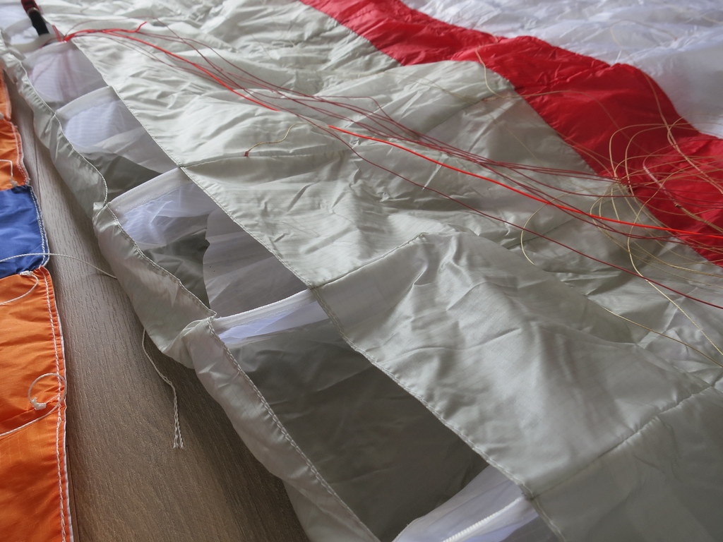
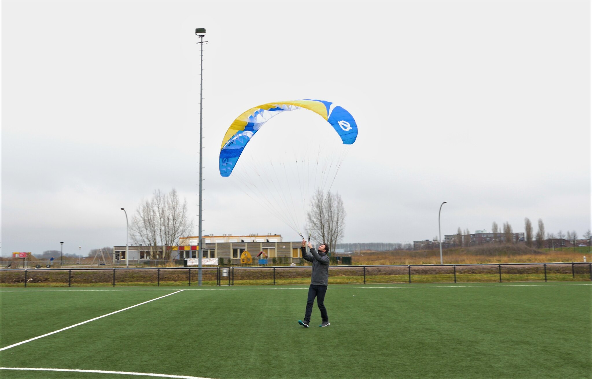
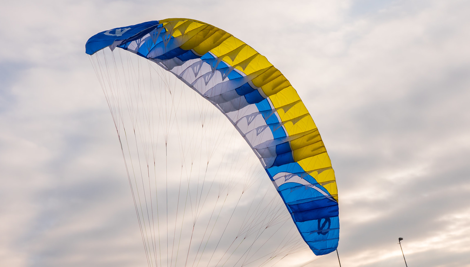
So the wing I bought back then is an Opale FOX RS 2.6:
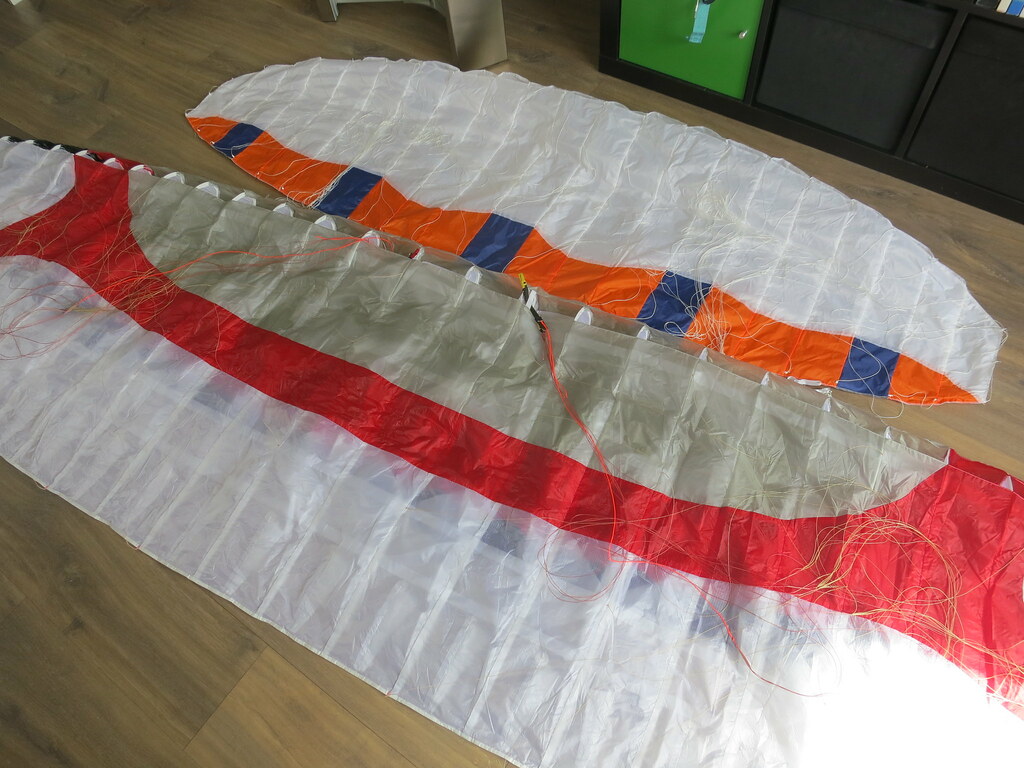
This wing can be flown with winds up to 20 knots and 7 kg payload (please note that
this is in optimal conditions and according to the manufacturer)
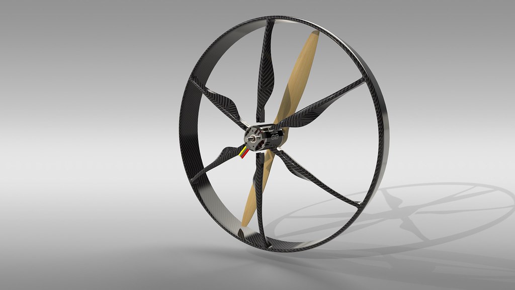
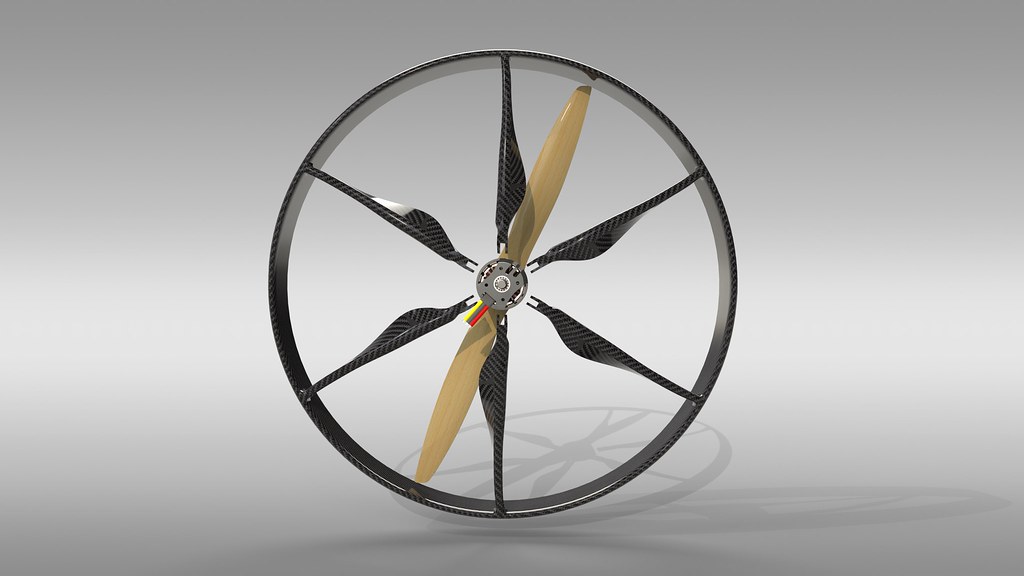
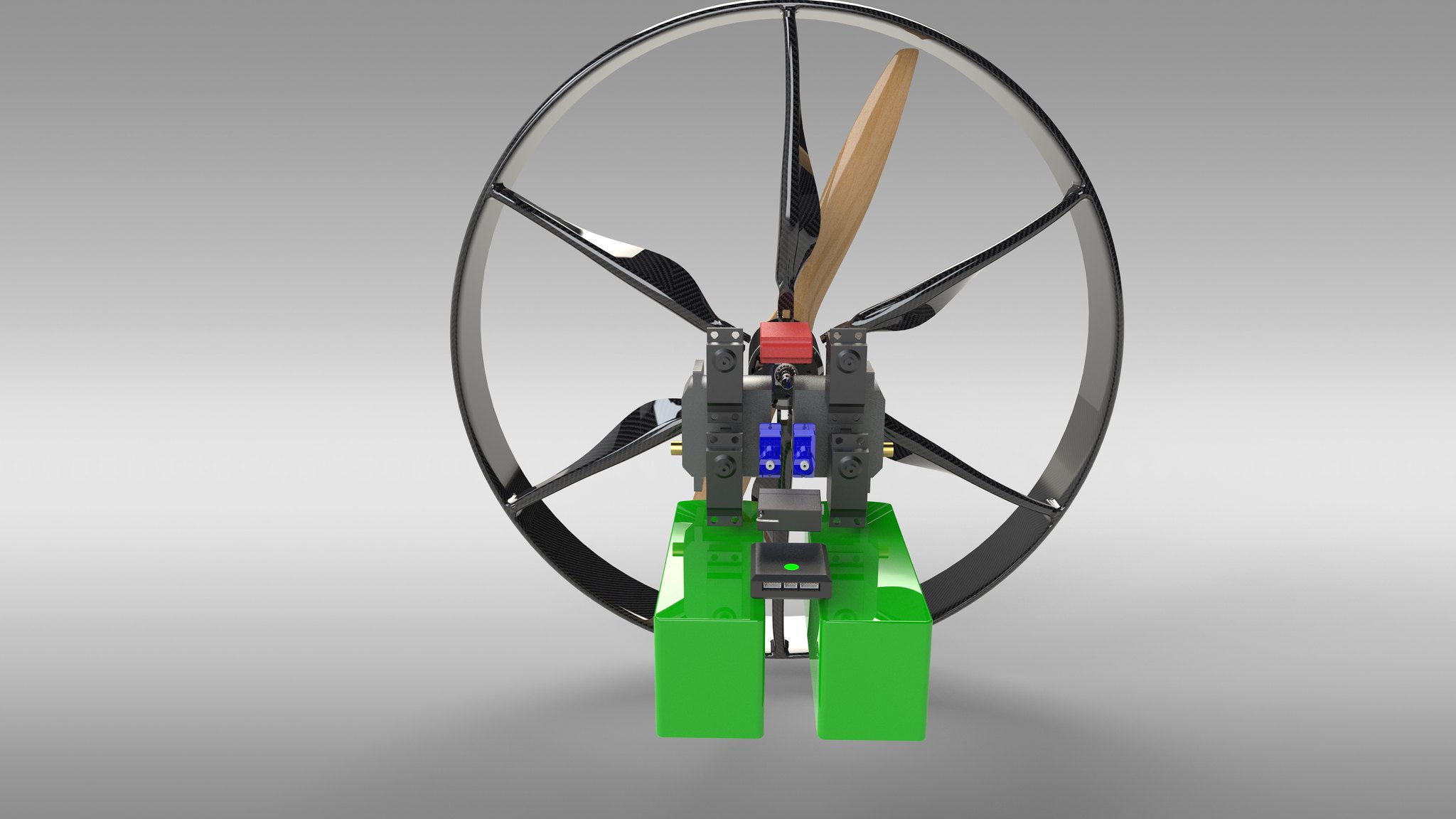
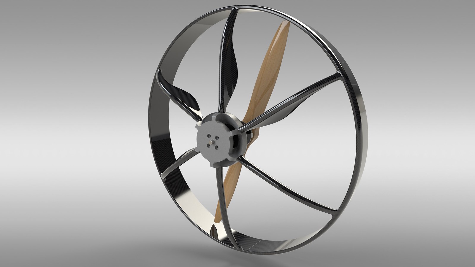
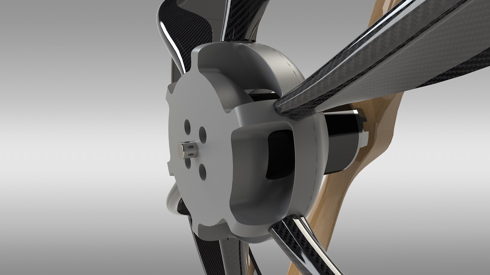
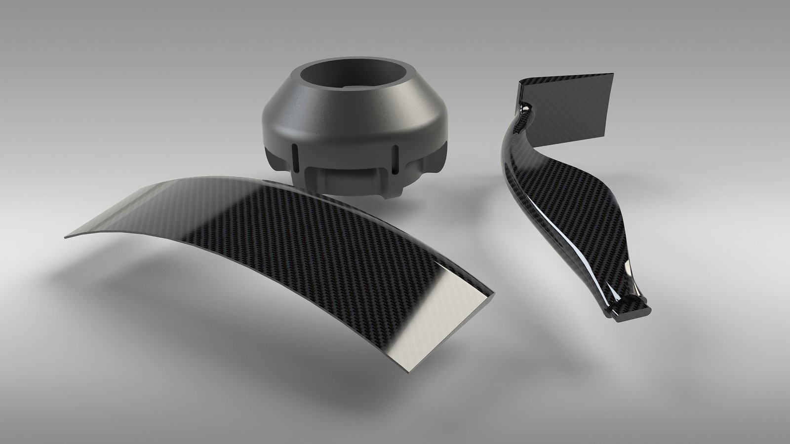
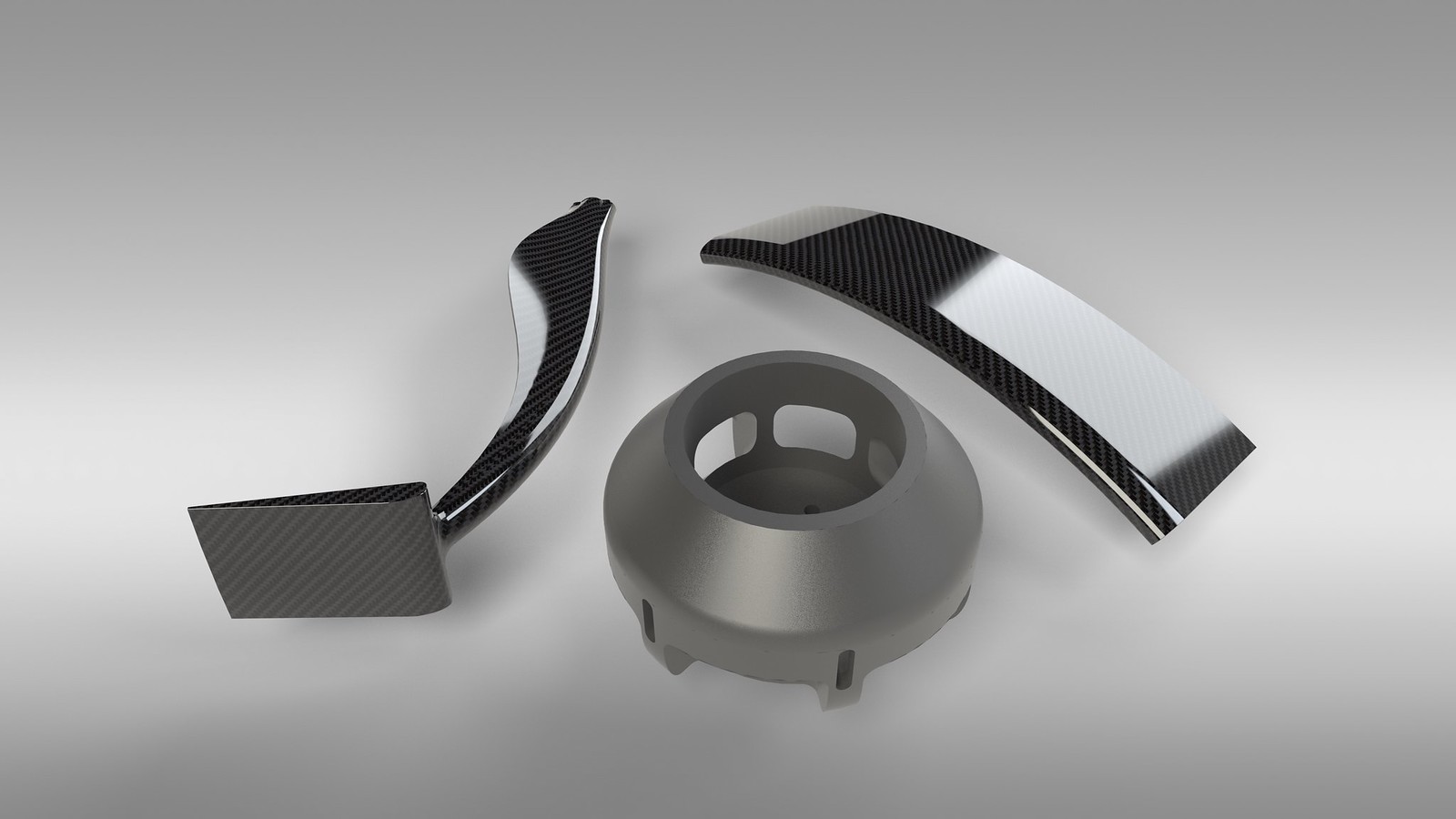
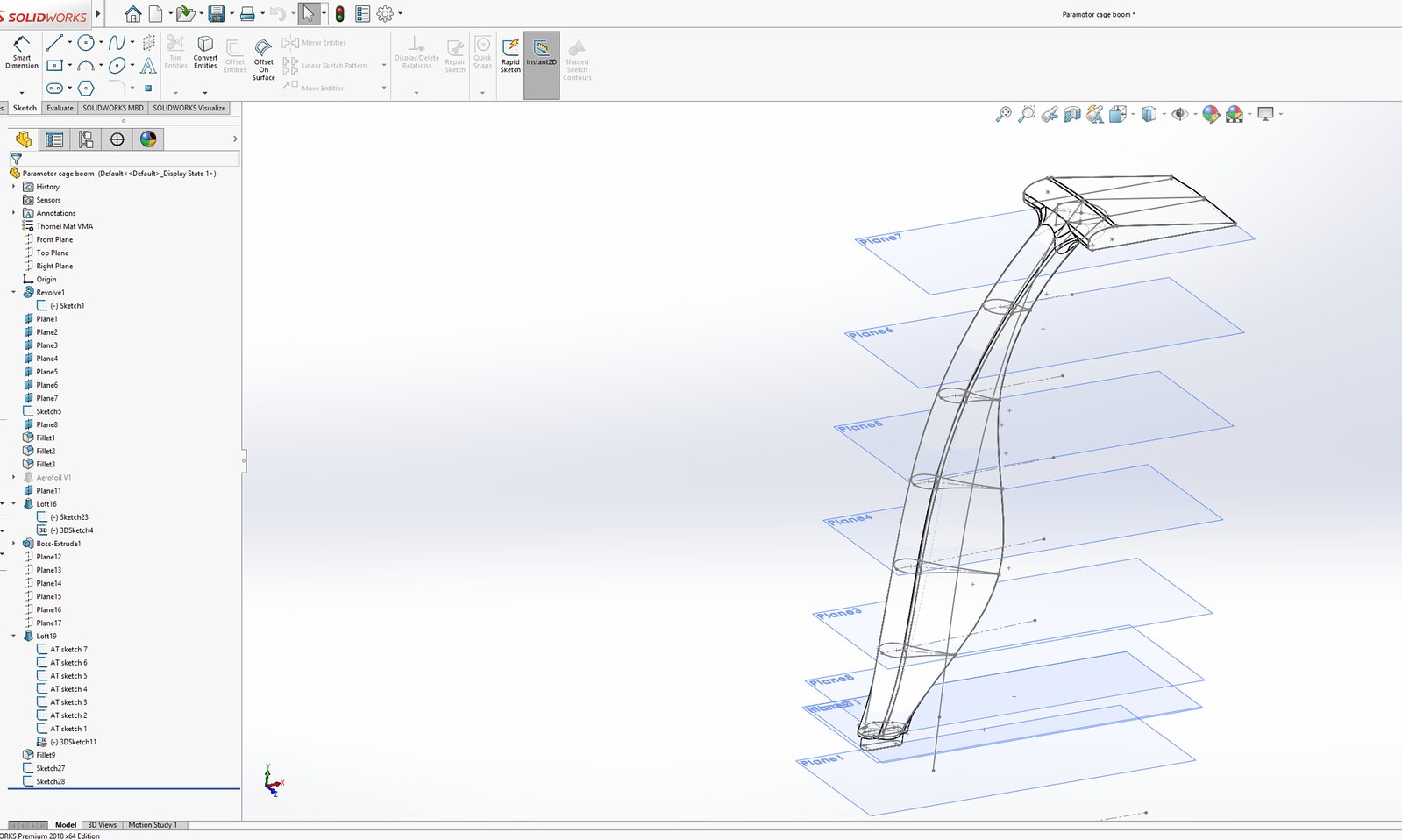
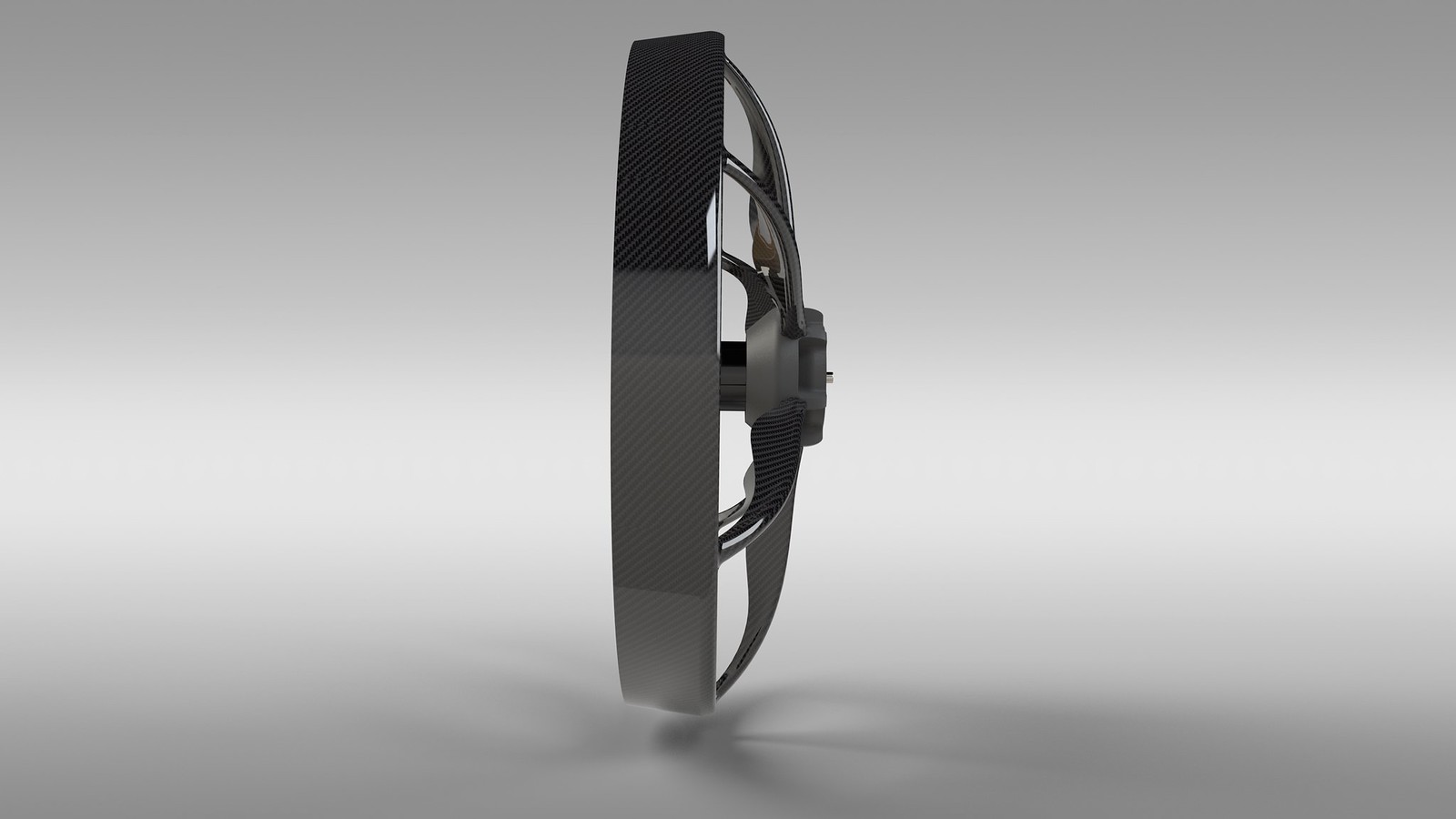
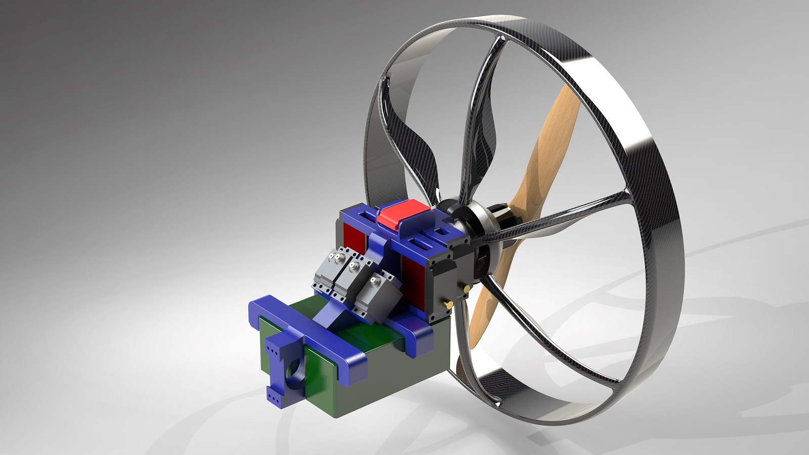
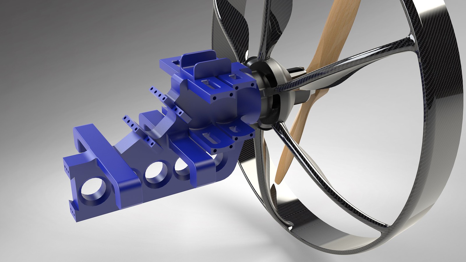
About a year ago I made a concept of what the propulsion unit (or trike/backpack) could
look like. Here is a quick render I made of that:
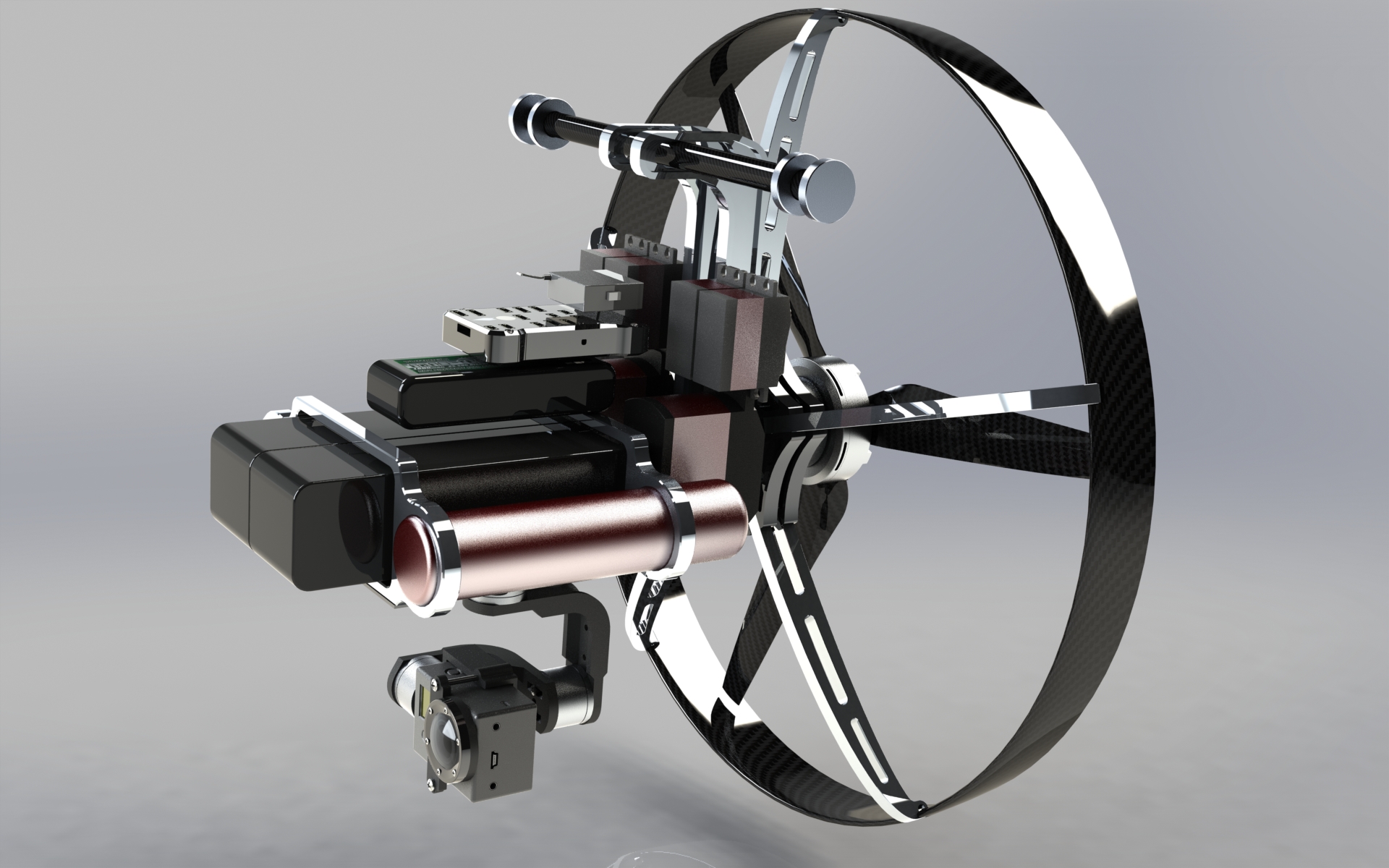
There are a lot of things that I will change to this concept, the main changes are:
- Riser mounting points will be adjustable for easy CG adjustments
- Gimbal will become retractable (this will make it less likely
that it will be damaged during landings)
- The flightcontroller will be a Pixhawk mini instead of the larger version
- The airbags will be likely replaced for a landinggear
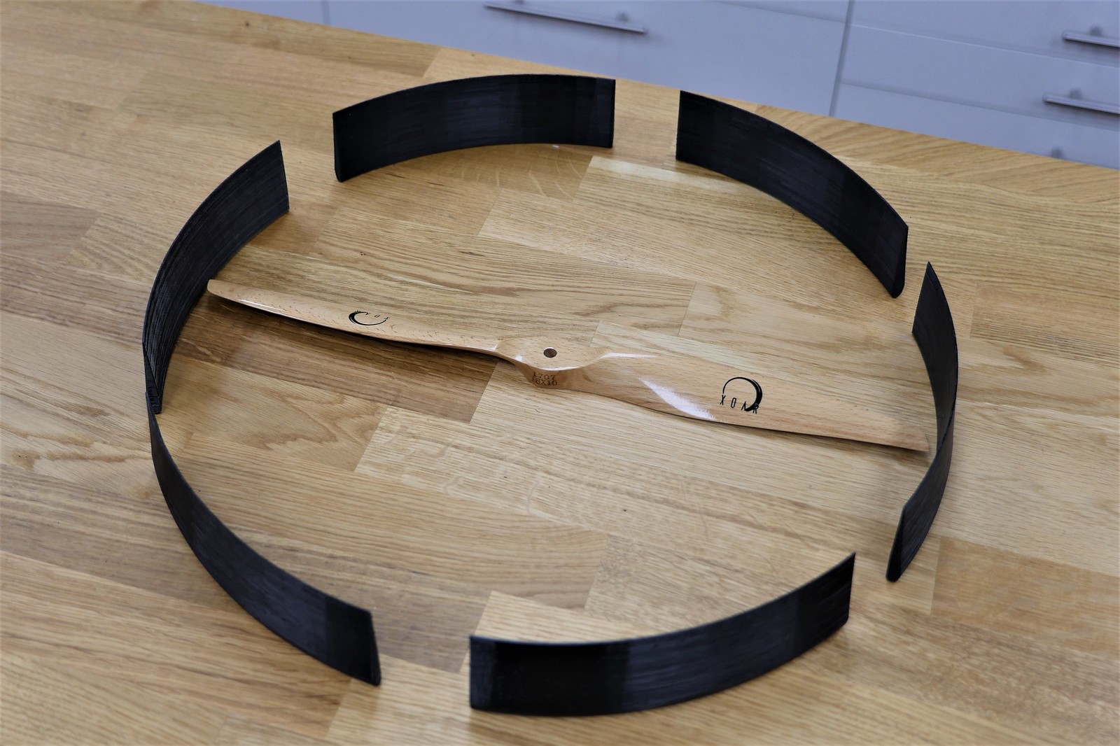
- I will use a 2 blade prop instead of the shown 3blade. (Xoar 18x10)
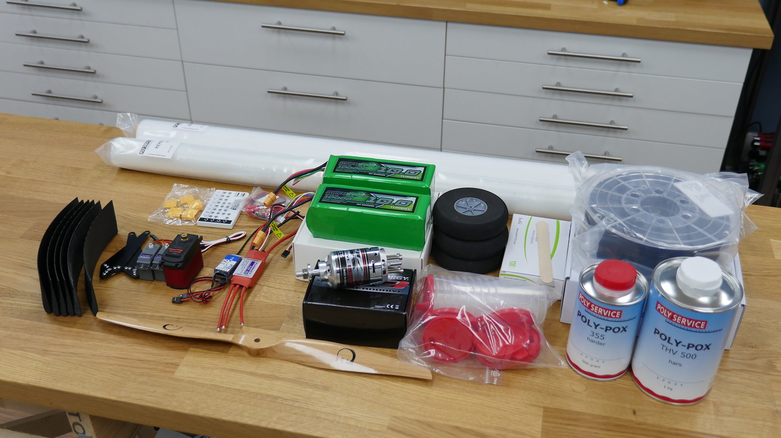
I ordered a couple of items yesterday and recieved most of it today in the mail
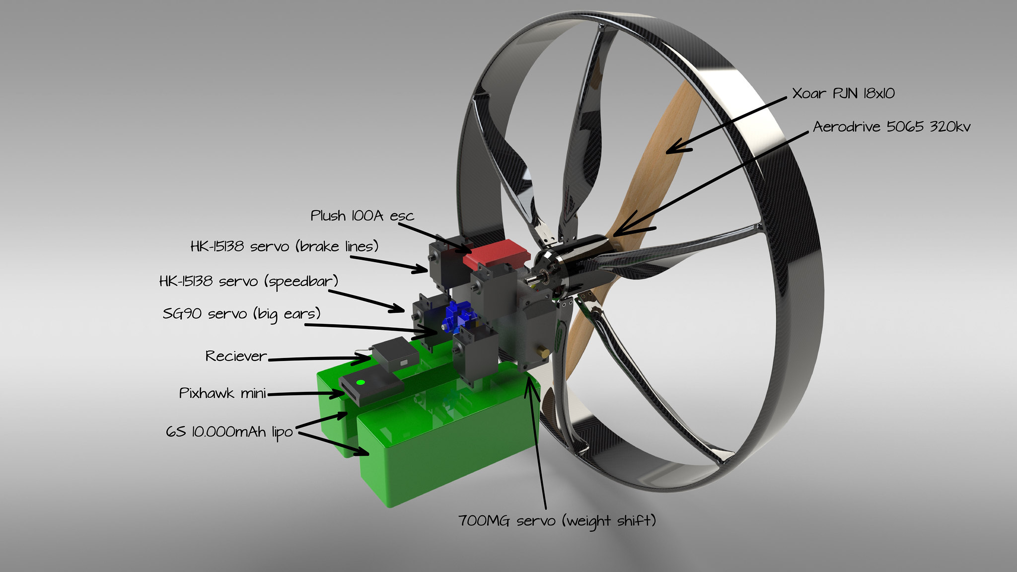
What I plan to use:
1x - Pixhawk mini controller (with current sensor, airspeed sensor and GPS)
1x - Plush 100A ESC
1x - YEP 20A BEC
1x - Aerodrive 5065 320Kv motor
1x - Xoar 18x10 propeller
2x - 6S 10.000 mAh battery
2x - TS700MG servo (weightshift steer)
2x - HK15138 servo (brake lines)
2x - 9gram servo (speedbar)
2x - 9gram servo (big ears)
Would you guys like to see the build in detail or would sharing the results suffice?
Ey guys! This is my first real post (besides the "mandatory" introduction post)
and am excited to share my new project!
So I bought a wing from Opale almost 3 years ago, planning to build a cool camera
platform but unfortunately I did not find the time to actually build it. Untill now
that is! I decided with the new year that it is time to get this project started and
share my experiences along the way.
In a nutshell the goal:
"having a paramotor fly autonomous with a camera/gimbal attached for endurance flights"
So why a paramotor? There are a few reasons that inspired me:
- "cheap" for the size and payload capability
- Really compact when in storage or during transport
- Silent (well at least in comparison to multicopters)
- Efficient, there is not a lot of power needed compared to
multicopters (planes can be more efficient but also more
expensive and a lot bulkier in storage and during transport)
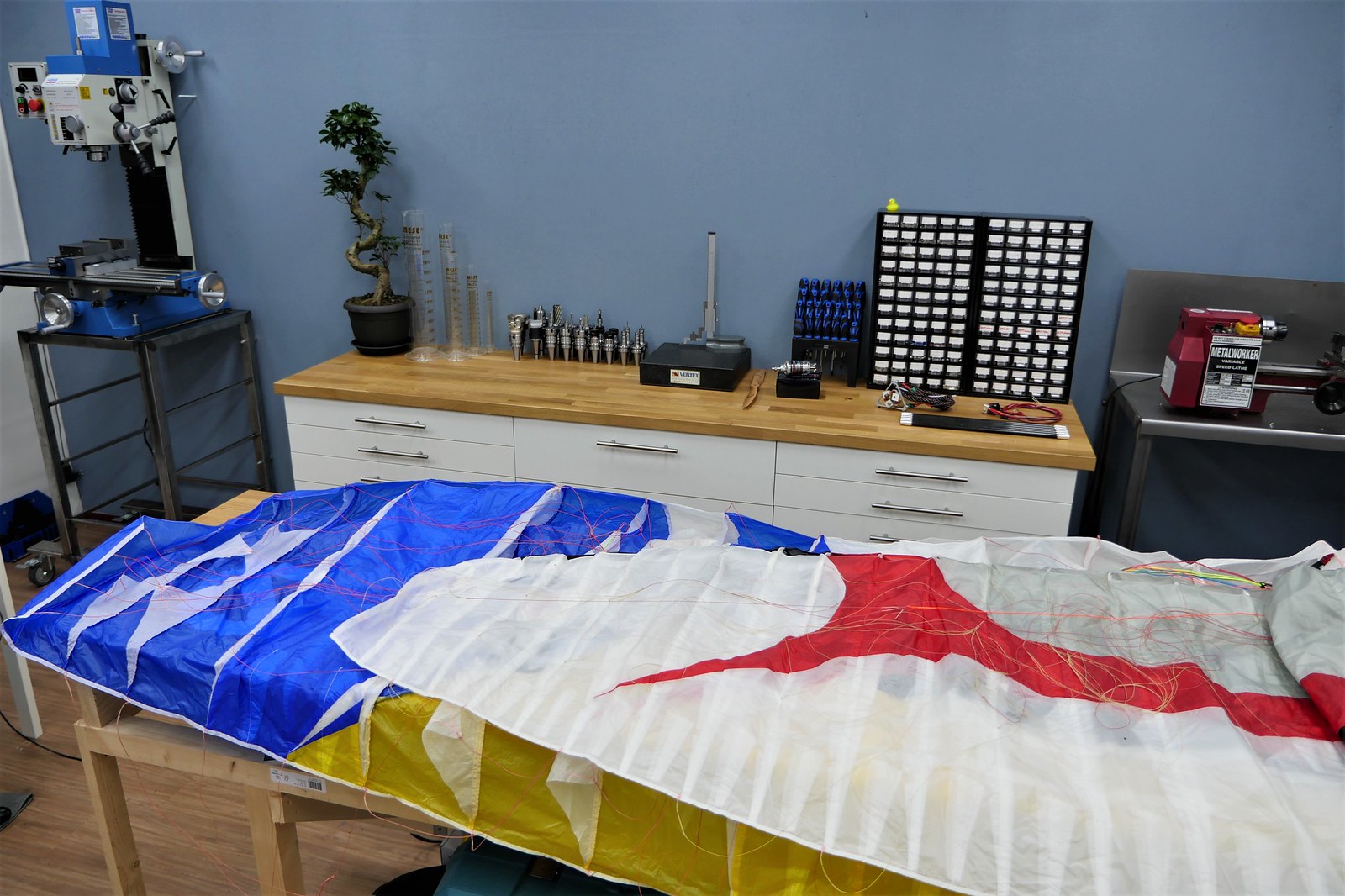
So the wing I bought back then is an Opale FOX RS 2.6:
This wing can be flown with winds up to 20 knots and 7 kg payload (please note that
this is in optimal conditions and according to the manufacturer)
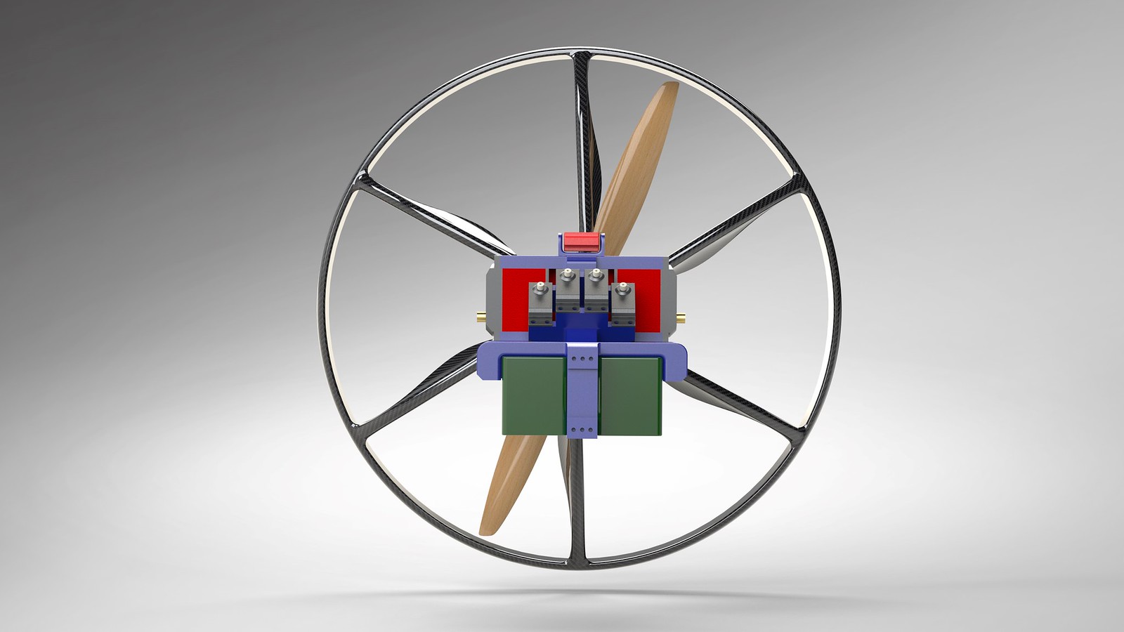
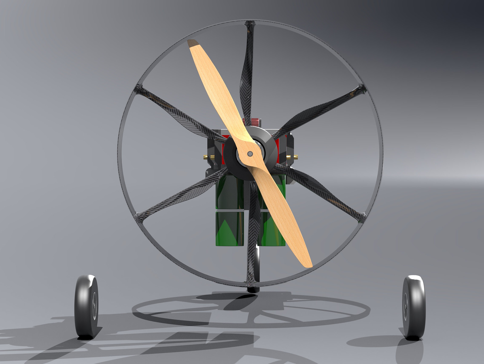
About a year ago I made a concept of what the propulsion unit (or trike/backpack) could
look like. Here is a quick render I made of that:
There are a lot of things that I will change to this concept, the main changes are:
- Riser mounting points will be adjustable for easy CG adjustments
- Gimbal will become retractable (this will make it less likely
that it will be damaged during landings)
- The flightcontroller will be a Pixhawk mini instead of the larger version
- The airbags will be likely replaced for a landinggear
- I will use a 2 blade prop instead of the shown 3blade. (Xoar 18x10)
I ordered a couple of items yesterday and recieved most of it today in the mail
What I plan to use:
1x - Pixhawk mini controller (with current sensor, airspeed sensor and GPS)
1x - Plush 100A ESC
1x - YEP 20A BEC
1x - Aerodrive 5065 320Kv motor
1x - Xoar 18x10 propeller
2x - 6S 10.000 mAh battery
2x - TS700MG servo (weightshift steer)
2x - HK15138 servo (brake lines)
2x - 9gram servo (speedbar)
2x - 9gram servo (big ears)
Would you guys like to see the build in detail or would sharing the results suffice?
Last edited:

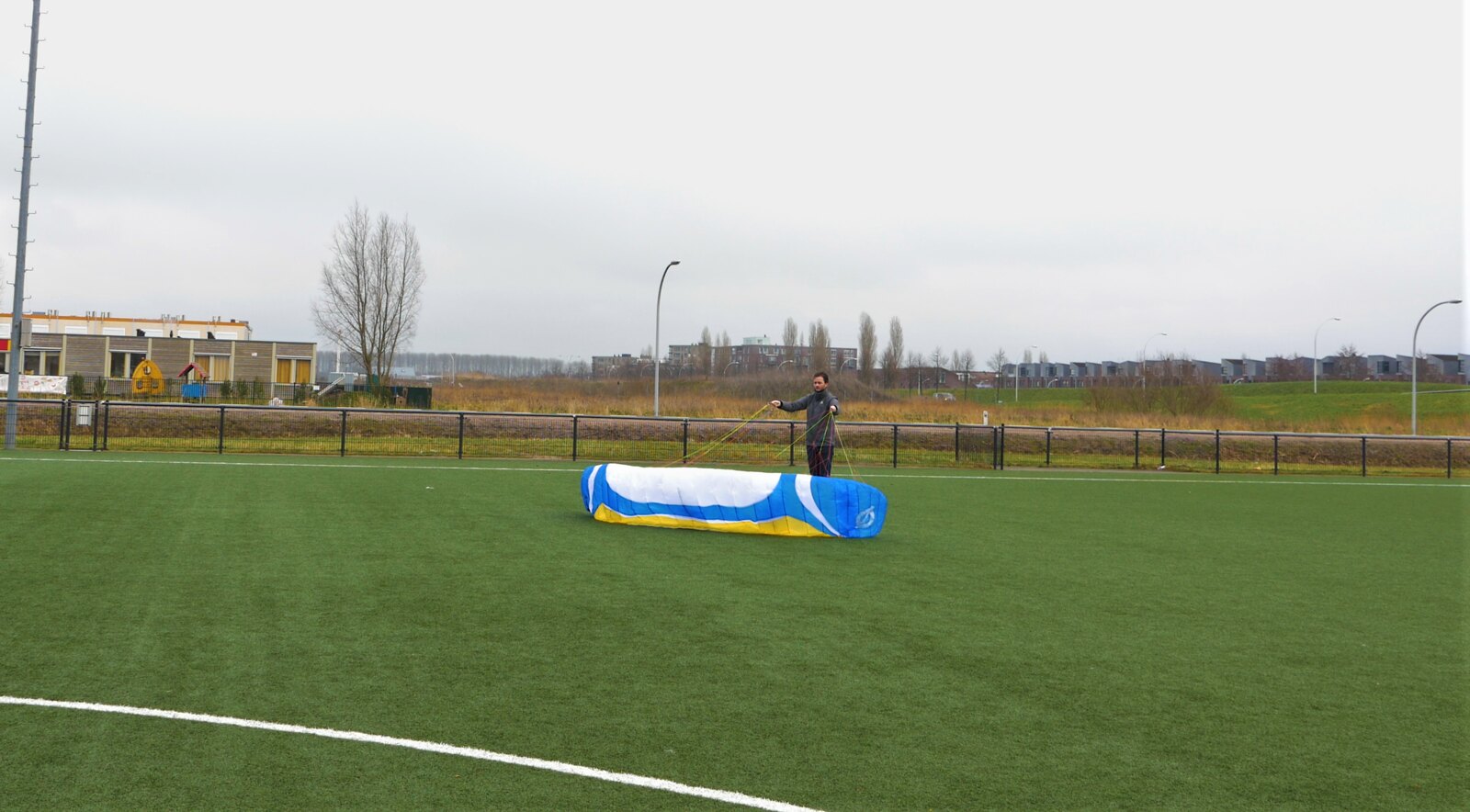
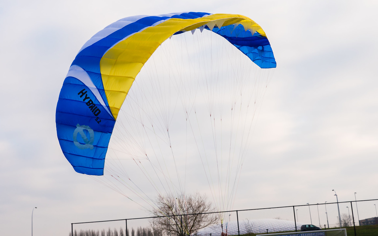
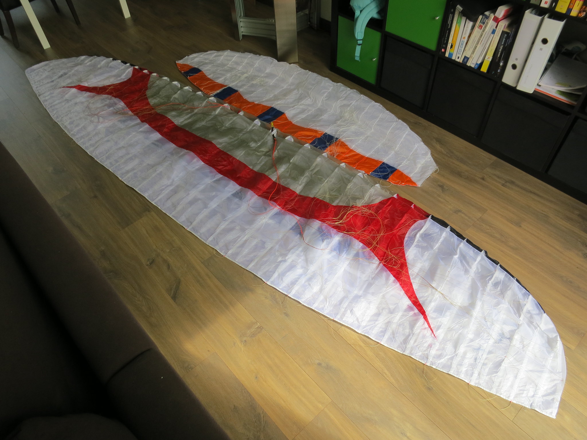
") (the wings are not even halfway unfolded)
(the wings are not even halfway unfolded)