Autonomous paramotor for aerial filming

And the result of this test. I am happy with it!

Just after applying it on the print
41605282064_8104162cc1_b.jpg

40521169870_9605e1ab0e_b.jpg


This morning besides the first test. Quite a difference!
40521169560_960089a918_b.jpg


I do need a bit more resin (there are a few voids) but I still count it as a succes and I'm
ready for the propeller cage itself now!
 
Thanks! I got the propeller cage glued together now, I did a test fit and the clearance is just how I wanted it to be!
The clearance between the propeller and the duct is 2mm with the closest point beeing 1.8mm and the widest 2.2mm

Top view
41442074255_3eeb0ce04b_h.jpg


Prop clearance
27474563387_3eeb0ce04b_h.jpg


Closeup on the gap
41442074165_33860d1b7f_h.jpg


With the test piece leaning against it
41442074045_79374ad749_h.jpg
 
Well that was quite an enormous fail... I changed the cut template (for the fabric)from one to a two piece version thinking it would help me out lamingating around weird shapes and curves. Unfortunately this thing that was suppose to help me became the biggest obstacle!

I had to pull all the carbon fiber off the printed ring and clean it up before it would set. It worked and I can go for a second try tomorrow but unfortunately it did cost me about 50 euro's in carbon fiber and resin.

oh well, thats how we learn right?
 
So a bit more information. Here you can see the 3 versions of the cutting templates. From left to right, where on the last one I decided to split it up in two (bad call!)

28642462138_bf85206f71_h.jpg

28642461828_73c2d93188_h.jpg


After a couple of hours of cutting that resulted in this, all carbon fabric prepared for laminating.
27645104557_c2c7810f52_h.jpg

28642461818_3d57a25837_h.jpg


Before that I allready prepared the spread tow ribbons by cutting them to length. These are still on the model, I decided to leave them eventhough I removed everything else because the application of these was actually successfull.
28642461948_9b12d11605_h.jpg


And the last picture for now, here you can see a cut piece of carbonfiber on the model, at this point everything still looked fine.
28642461498_328364af57_h.jpg
 
Update time! I've been kind of quiet last few weeks but definately got some nice (and less nice) progress on the project.

Well first lets get to the good stuff, not one but two update video's:

Buildvlog 4: A short video about the newly printed parts, sanding and the glueing.

Buildvlog 5: A video about experimenting with laminating and the failure of laminating the actual propeller duct
 
I've been coming up with excuses the last couple of months not to get on with the sanding but I can report that I am back on the project and am making some nice progress. The update video on the build itself will come soon!

In the meantime I made a video about the design and how it evolved into the current shape. I'm also looking for some feedback there. Thanks in advance!


(oh this is the first video with this kind of format, it may feel a bit messy but I imagine that it will improve in future video's. Besides that it is still somewhat superficial because if I wanted to get into all the details the video wouldn't be 9 minutes but closer to 6 hours. If you have any questions let me know!)
 
At the moment I am back on sanding the paramotor. In a few weeks there is a paramotor meeting not too far away from where I live and I really want to attend that and bring at least a laminated propeller cage. So I better get to it! I did some experiments with the finishing of the carbon fiber. I got a finish that I am happy with (not perfectly finished but didn't think is was needed for a testpiece)
44467870822_8064c54adf_h.jpg


Oh and a little proof that I am actually sanding :p :
44467870712_7facfc61b7_h.jpg
 
This time no video update but just some text and a couple pictures. I prettymuch started from scratch for this build from a cad perspective.
It's not that I made all the parts again but I did start over with the assemblies. The file I worked in untill now was a mess, just as you'd expect
with a proof of concept. But now that I've made some nice steps with the design the file and design structure really needed an update.

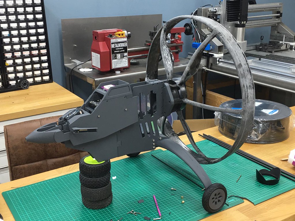
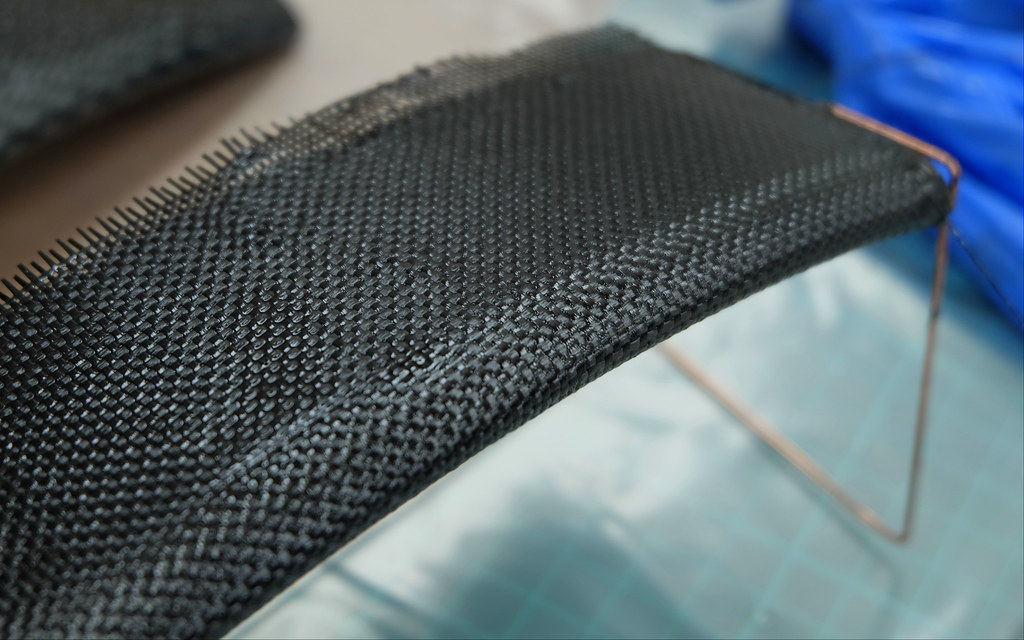
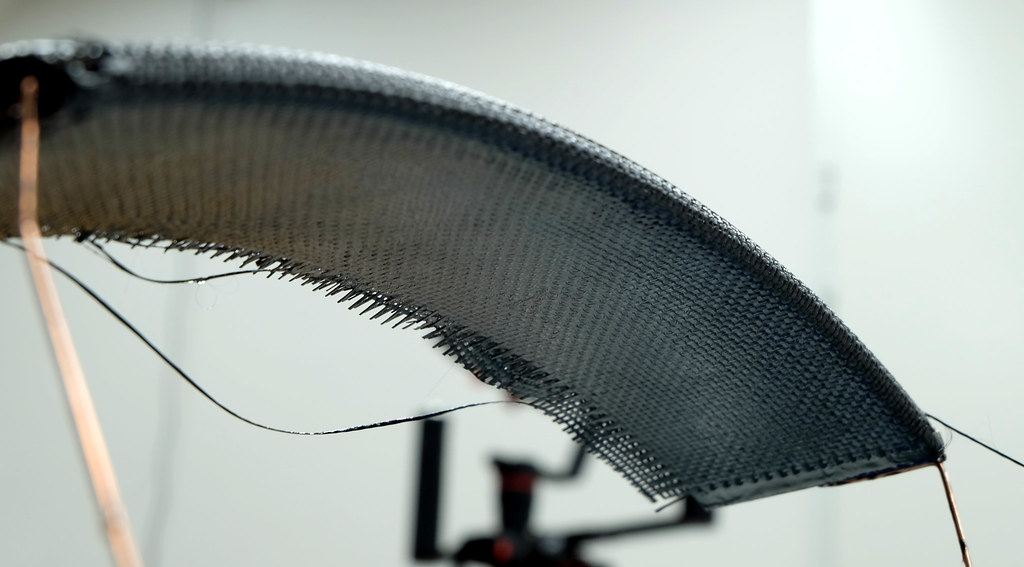
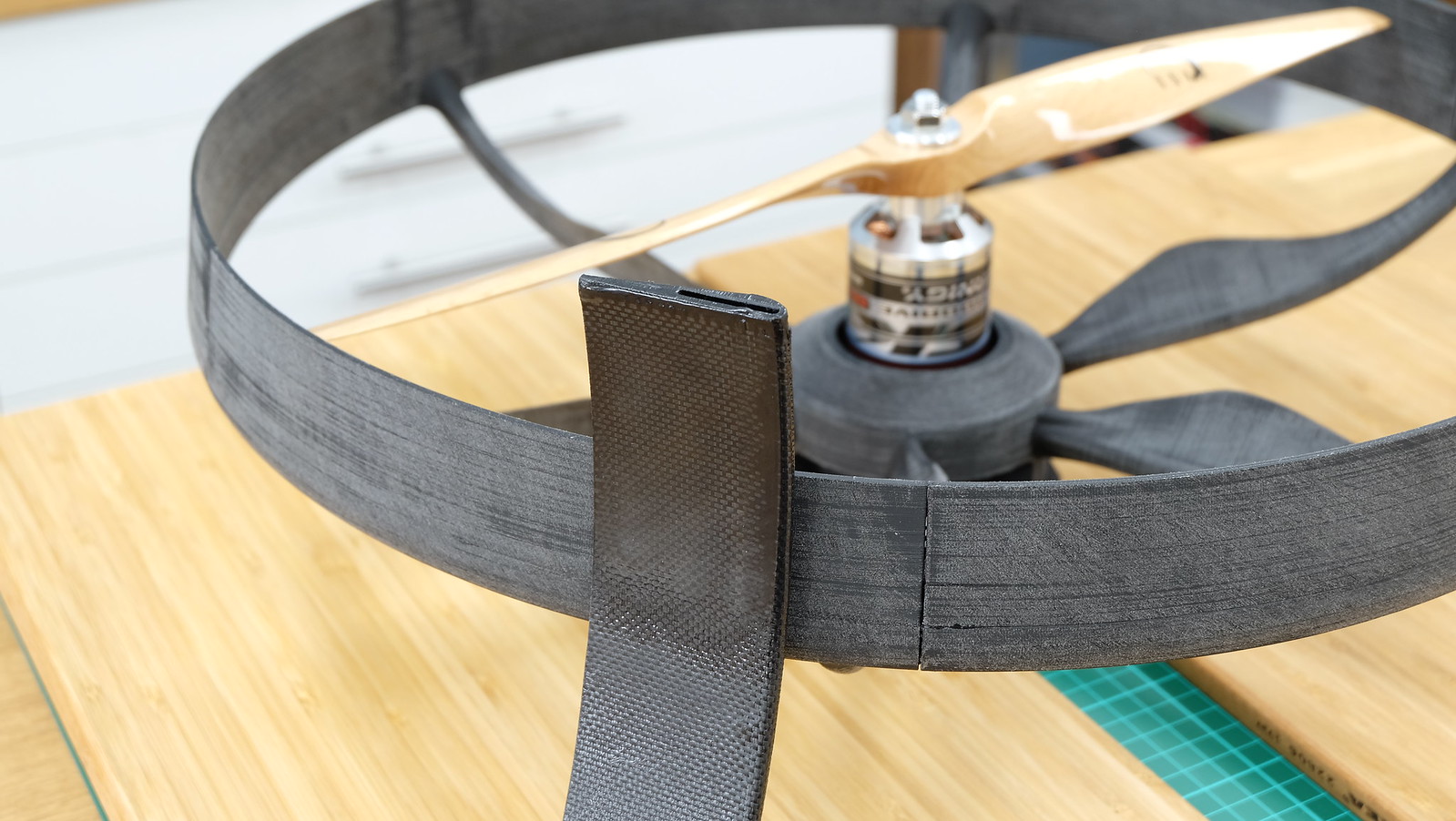
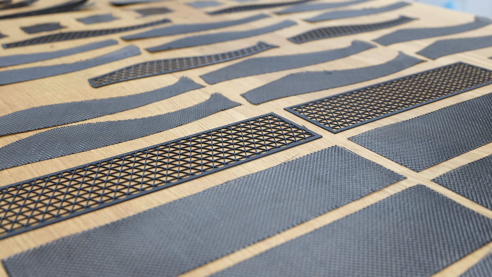
As I explained in the last video, I decided to take the classic frame approach (just like RC helicopters) for this build. I'm going to make a couple
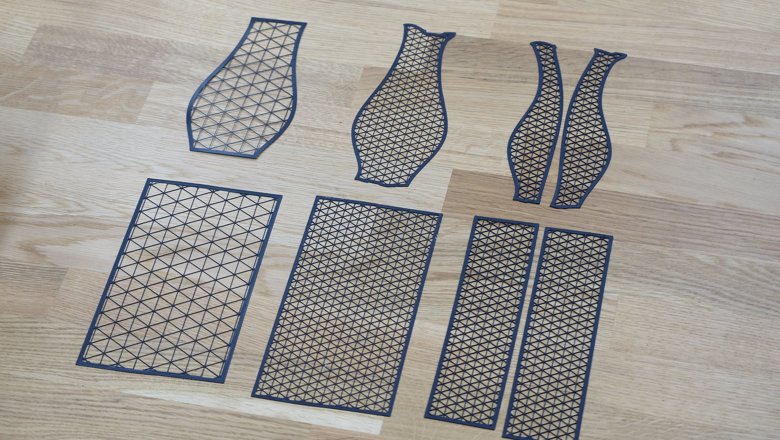
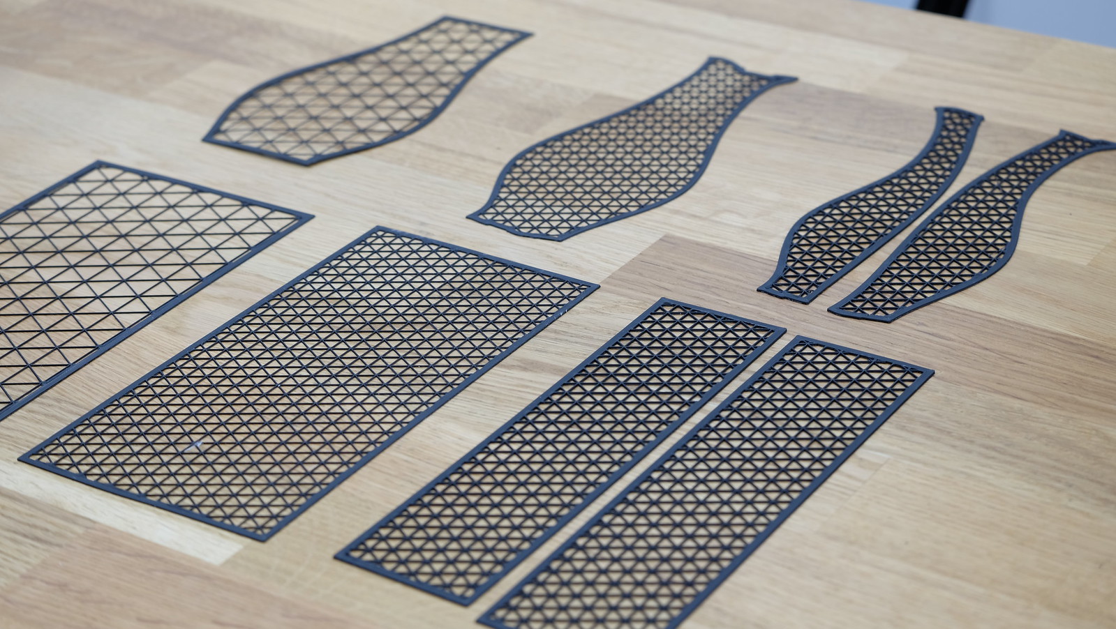
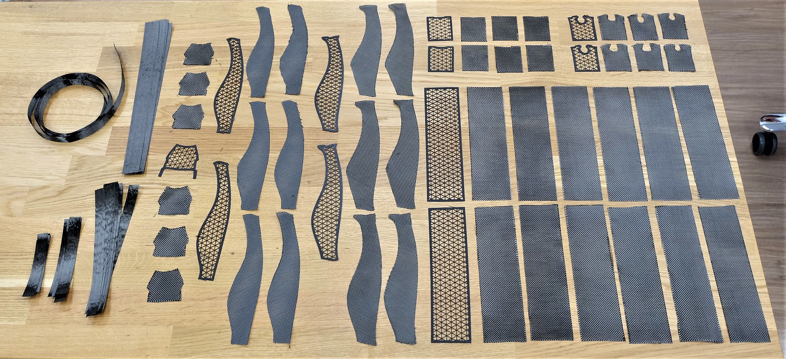
carbon frames that make up the backbone of the model and all components are bolted to this backbone. I made about half of the mounts and
am testfitting the parts in preparation of cutting the frameplates. I'm going to make those as the final step when I am sure that the positions of
the parts are correct, I obviously don't want to mess up a nice sheet of carbon fiber if I can testfit and troubleshoot in advance.

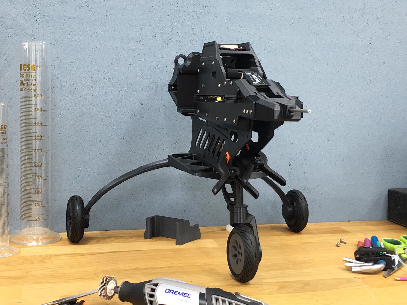
So on to the pictures!

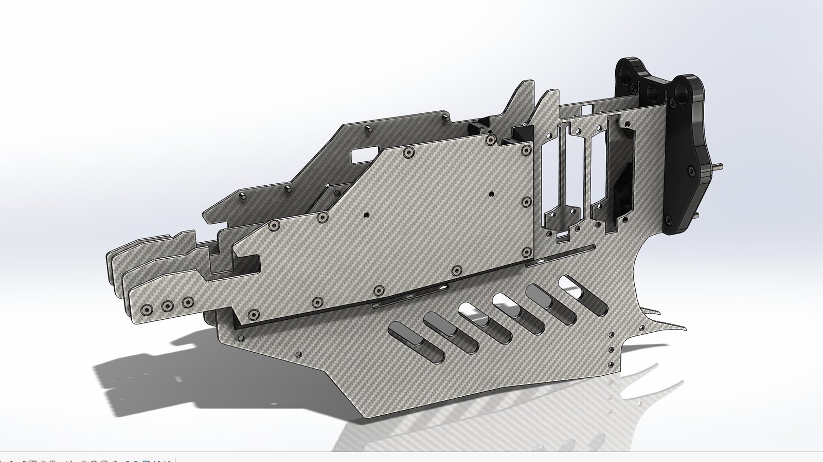
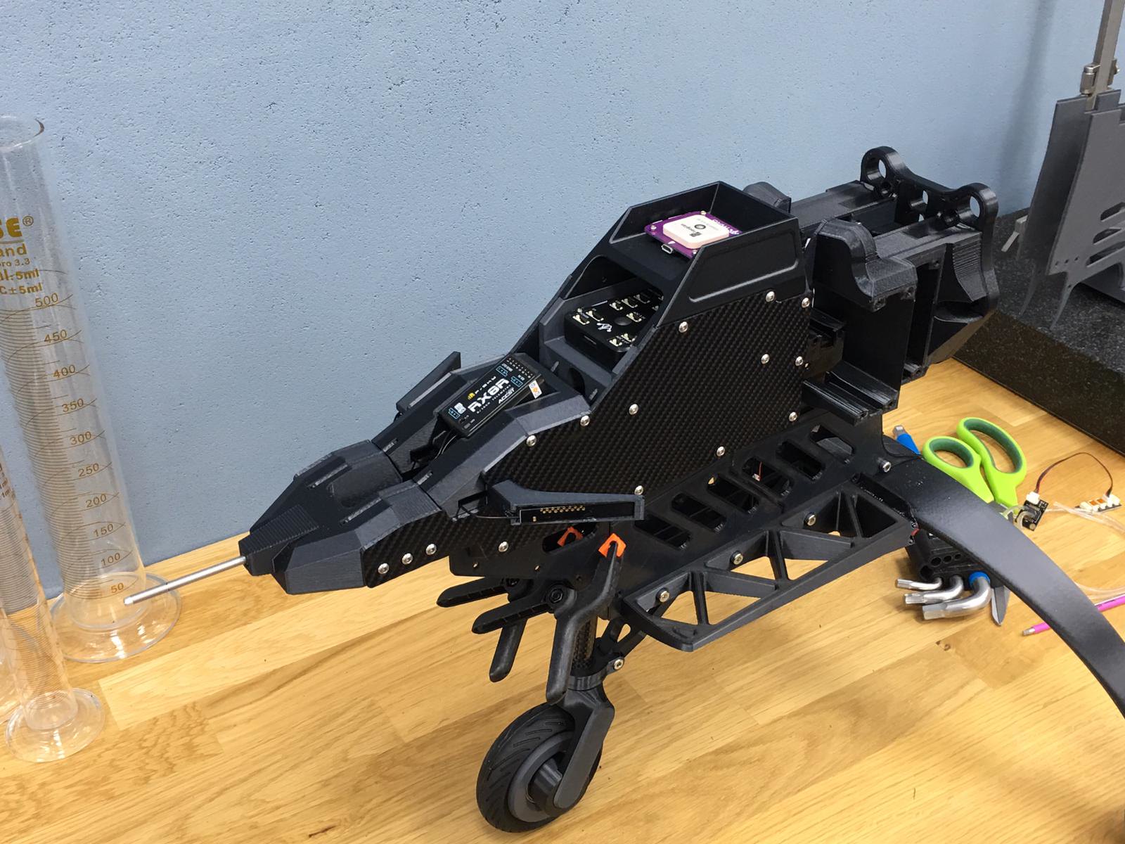
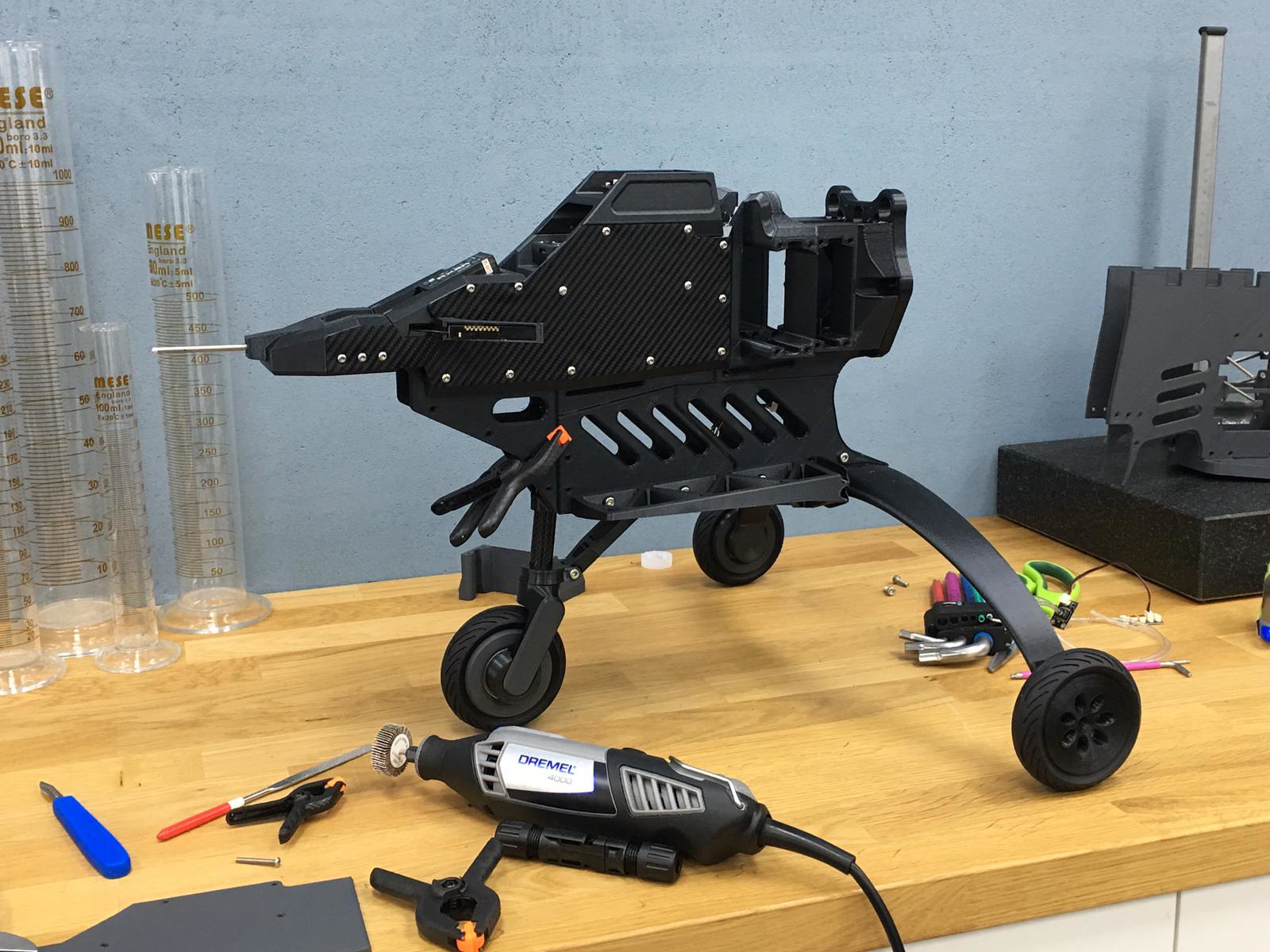
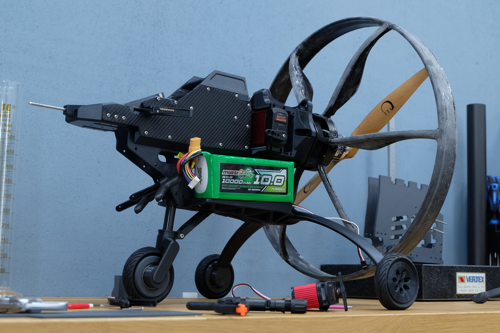
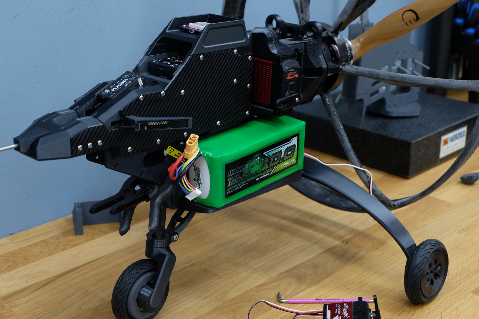
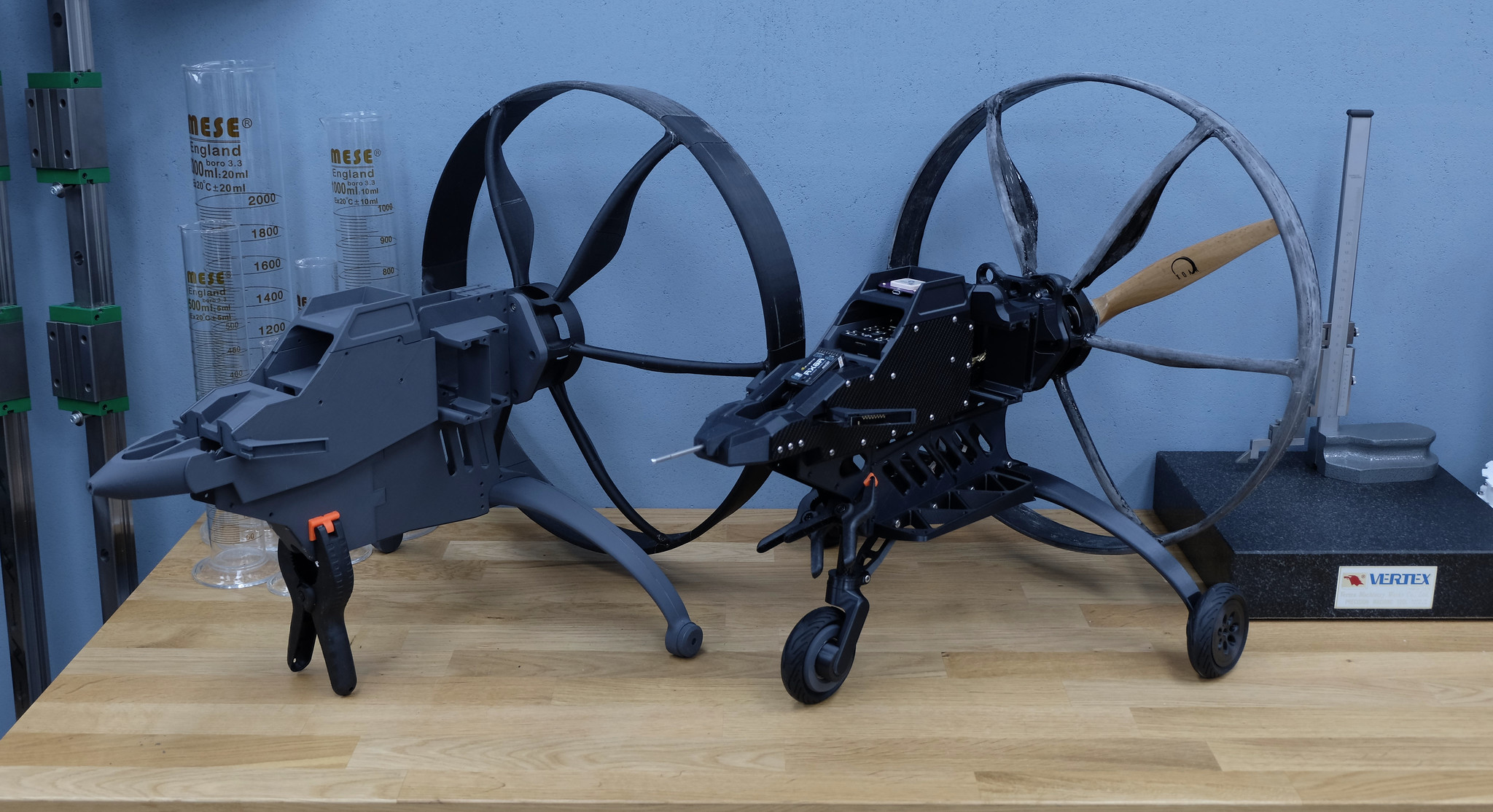
Front/side view without canopy
44743938574_3777ce3d77_k.jpg


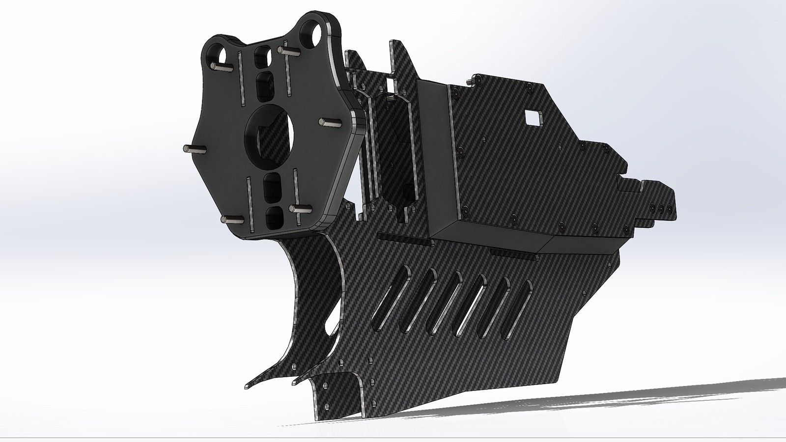
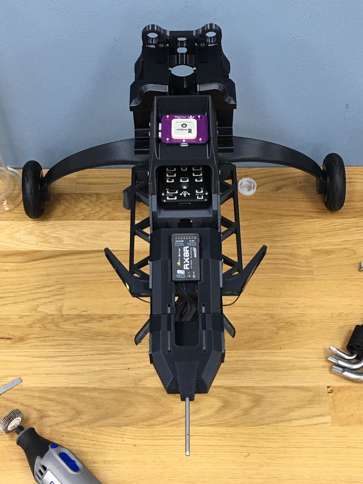
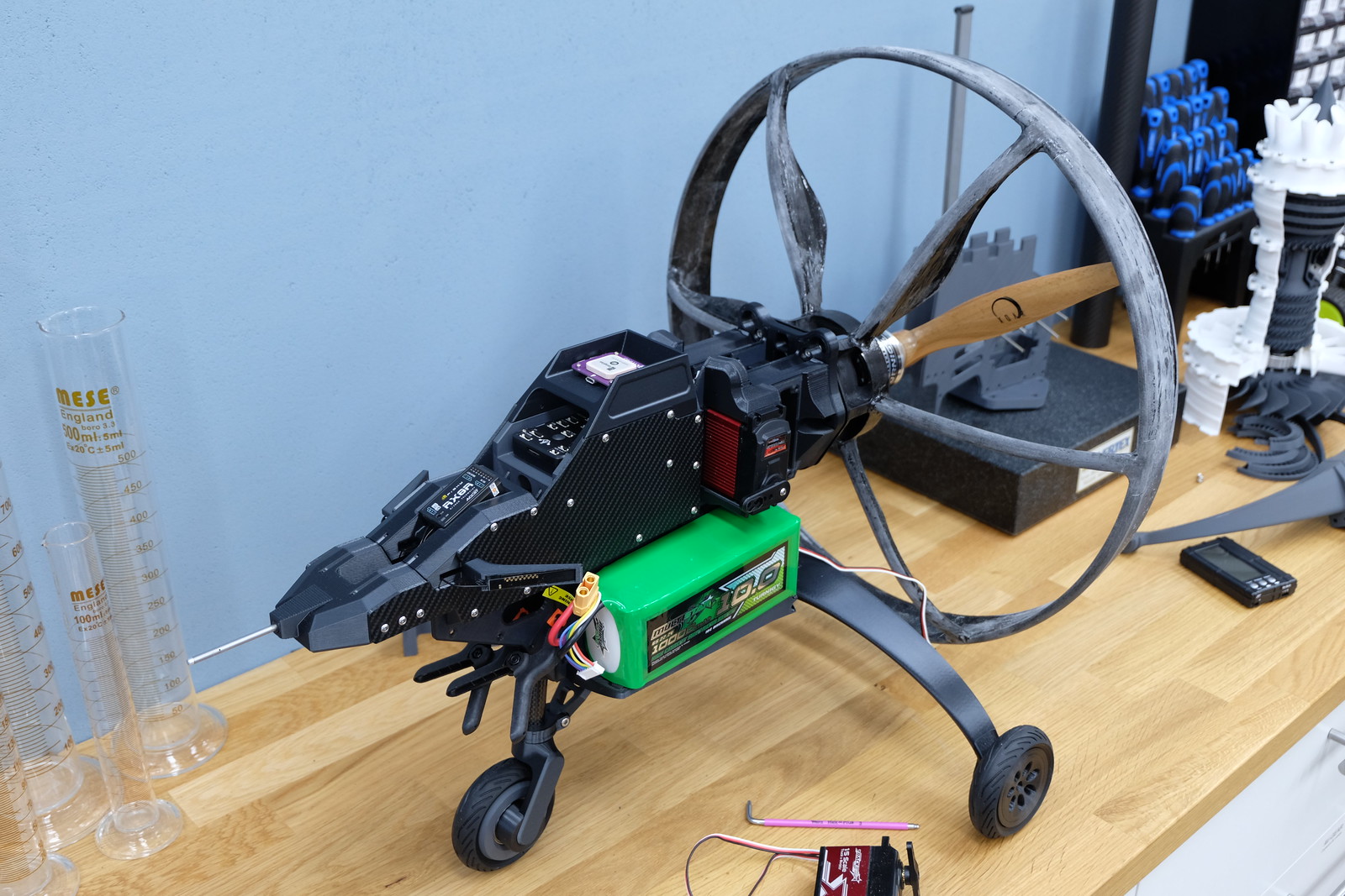
Topview with a nice view of the component layout
31594184258_3fccbe1184_k.jpg


45468948281_b22b26eedf_h.jpg


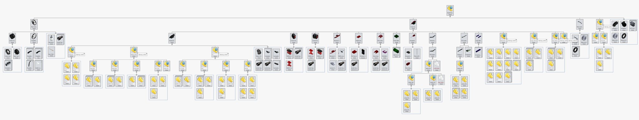
As I said, I'm fixing the assemblies and am trying to create some structure. This means that the parts are put in subassemblies that make sense and those subassemblies are mated in the final complete assembly. Solidworks has a nice tool that helps visualize the structure of the model called "treehouse"

45478061511_a04844f3ab_k.jpg


This overview isn't complete but does give a realistic pretty accurate view of the build.
 
I tried to work a bit more on the project last december but I really lacked in creativity. I had enough other things
to work on so I just let it rest a bit more. The past few weeks I had a lot of inspiration and ideas to finish this project
so I made quite a bit of progress! As you may expect, a lot has changed since my last update but I am happy to say that
these will be the last big changes. I made the frame parts that will hold electronics, batteries etc. in their final form and
as test (to check fit and function) also printed the frameplates. These will be watercut from carbon fiber in the next couple
of weeks when I have time.

Here a couple recent screenshots of the base frame:
47631272101_a0189a72f7_h.jpg


46906991124_b88a030530_h.jpg


33753988858_f9862aa832_h.jpg


And pictures of the frame in test assembly with the printed frameparts:
40664820553_861c028248_h.jpg


46906991984_41dbf549f0_h.jpg


33753990728_c0d6f700b3_h.jpg


47631273061_04c52450c9_h.jpg


Obviously without the propeller cage assembly, I haven't had the time to install that
on this final version but to give an idea of the overall proportions a picture of the
previous version:
32690017007_4c8d34e8a1_b.jpg