free_flyer
Junior Member
Hey all!
A friend and I recently did an open ended class project for our college-level fluid dynamics class, and we chose to analyze circle planes (annular winged aircraft). Here are some interesting things we learned that we wanted to share with all those interested. Also, at the end of the post we have posted a video of our own circle plane flight test video with a plane similar to that done by Peter. So if you want to see what we're talking about in action, look no further.
Motivation for the Project:
Annular (circular) wings are interesting because they theoretically have some advantages over traditional wings. To put it simply, annular wings would have no wingtip vortices in an ideal world--because they have no wing tips! This is great because for R/C-scale flight, wingtip vortices account for a large portion of the total drag on the aircraft. In reality however, wingtip vortices will never disappear entirely as long as lift is being generated. For our project though, we wanted to see how well an annular wing minimized wingtip vortices, and then to compare the Lift-to-Drag ratio of the annular wing to a conventional wing. For more info about wingtip vortices, follow this link:
https://en.wikipedia.org/wiki/Wingtip_vortices
To perform our analysis, we decided to use a powerful tool known as CFD (Computational Fluid Dynamics). In our case we used a CFD program called STAR CCM+.
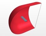
Here are the two computer-generated 3D geometries we analyzed with with STAR CCM+:

An annular wing (note only half is shown due to symmetry)

A conventional (finite) wing with the same span (once again only half is shown)
For those unfamiliar with CFD, CFD creates a virtual wind tunnel composed of thousands of tiny cells that model the interaction of fluid flow on a body of interest (in this case: wings). If we carefully choose the right parameters and settings for the CFD program, we can obtain an accurate representation of what the fluid is actually doing, and thus be able to determine useful things such as lift and drag.
Here's a shot of the cells that were used around the wing to do our CFD calculations:

For our CFD simulation, we used local atmospheric conditions to analyze both wings when flying at 12 m/s. We hoped to find that the annular wing would have smaller wingtip vortices than the conventional wing. Smaller wingtip vortices would lessen the drag force.
After running CFD on the two geometries shown above, here are some pictures of our results:

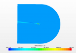
This scene shows the vorticity (strength of wing-tip vortex) at the wing tip of the annular wing

This scene shows the vorticity at the wing tip of the conventional wing
Note that in the two pictures above, the scale of the vorticity of the annular wing is much less than that of the conventional wing.
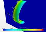
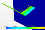
These first pictures provide some useful information, but they're not very exciting. To visualize more of what's going on, we created a 3D representation of the the vorticity over the entire wing surface. In the pictures below, what you're seeing are the parts of the wing's wake where there is high vorticity.


From looking at the two pictures above, we can see that with the annular wing there are small sections of vorticity distributed pretty evenly around the trailing edge of the wing. On the conventional wing, we see that most of the vorticity is right at the wing tip as expected.
So from these results, it looks like the annular wing is effective at reducing the wingtip vortices. Cool!
But what about the Lift-to-Drag ratios? Here's what we found:
Annular wing: L/D = 15.06
Conventional wing: L/D = 21.47
So what happened? Why was the Lift-to-Drag ratio of the conventional wing better? Well as it turns out, there are a few factors that affect lift and drag. For lift, you can probably understand how the vertical side sections of the annular wing don't produce much lift. For the conventional wing, the whole wing is able to contribute lift. Then there's drag. Drag comes in two main forms namely pressure drag, and friction drag. Because the circular wing reduced the wingtip vortices, this lead to a reduction in pressure drag. The problem though, is the friction drag. Since friction drag is related to the surface area of the wing, the annular wing had much more friction drag than the conventional wing because it had about 3 times as much surface area. This resulted in the total drag of the annular wing being more than that of the conventional wing. The conventional wing also generated slightly more lift. It was this combination that resulted in a lower lift-to-drag ratio for the annular wing.
In the end we did find something promising about the drag on the annular wing. If instead of computing the total drag, we computed something called the drag coefficient, we saw that the annular wing had a smaller drag coefficient than the conventional wing. The reason for this is that the drag coefficient takes into account the total surface of area of the wing, and then divides by it. So what the lower drag coefficient for the annular wing is really saying here, is that per square foot or square meter of wing surface area, the annular wing has less drag. Here are the actual numbers we calculated:
Annular wing: C_d = 0.0074
Conventional wing: C_d = 0.0097
In the end, our project and analysis showed that annular wings are more of a novelty in aviation than they are practical. We did have lots of fun learning about and analyzing them though! Perhaps the biggest advantage of annular wings is that, as we all know, you can fly through them! For this reason we think that airplanes with annular wings will continue to have an endearing presence in the R/C world for a long time to come.
Here's a video of the circle plane that we built and flew based on Peter's circle plane. If you've never built or flown a circle plane, we highly recommend it!
Video:
For those of you who have access to STAR CCM+ software, the simulation files that we used to obtain the above results can be found by following this link: https://drive.google.com/folderview?id=0BzaMyfYgNDEsQ2dxTlVBejI3eEE&usp=sharing
Taking a peek at these files may be helpful for anyone who wants to perform a similar simulation. Enjoy!
A friend and I recently did an open ended class project for our college-level fluid dynamics class, and we chose to analyze circle planes (annular winged aircraft). Here are some interesting things we learned that we wanted to share with all those interested. Also, at the end of the post we have posted a video of our own circle plane flight test video with a plane similar to that done by Peter. So if you want to see what we're talking about in action, look no further.
Motivation for the Project:
Annular (circular) wings are interesting because they theoretically have some advantages over traditional wings. To put it simply, annular wings would have no wingtip vortices in an ideal world--because they have no wing tips! This is great because for R/C-scale flight, wingtip vortices account for a large portion of the total drag on the aircraft. In reality however, wingtip vortices will never disappear entirely as long as lift is being generated. For our project though, we wanted to see how well an annular wing minimized wingtip vortices, and then to compare the Lift-to-Drag ratio of the annular wing to a conventional wing. For more info about wingtip vortices, follow this link:
https://en.wikipedia.org/wiki/Wingtip_vortices
To perform our analysis, we decided to use a powerful tool known as CFD (Computational Fluid Dynamics). In our case we used a CFD program called STAR CCM+.
Here are the two computer-generated 3D geometries we analyzed with with STAR CCM+:

An annular wing (note only half is shown due to symmetry)

A conventional (finite) wing with the same span (once again only half is shown)
For those unfamiliar with CFD, CFD creates a virtual wind tunnel composed of thousands of tiny cells that model the interaction of fluid flow on a body of interest (in this case: wings). If we carefully choose the right parameters and settings for the CFD program, we can obtain an accurate representation of what the fluid is actually doing, and thus be able to determine useful things such as lift and drag.
Here's a shot of the cells that were used around the wing to do our CFD calculations:

For our CFD simulation, we used local atmospheric conditions to analyze both wings when flying at 12 m/s. We hoped to find that the annular wing would have smaller wingtip vortices than the conventional wing. Smaller wingtip vortices would lessen the drag force.
After running CFD on the two geometries shown above, here are some pictures of our results:

This scene shows the vorticity (strength of wing-tip vortex) at the wing tip of the annular wing

This scene shows the vorticity at the wing tip of the conventional wing
Note that in the two pictures above, the scale of the vorticity of the annular wing is much less than that of the conventional wing.
These first pictures provide some useful information, but they're not very exciting. To visualize more of what's going on, we created a 3D representation of the the vorticity over the entire wing surface. In the pictures below, what you're seeing are the parts of the wing's wake where there is high vorticity.


From looking at the two pictures above, we can see that with the annular wing there are small sections of vorticity distributed pretty evenly around the trailing edge of the wing. On the conventional wing, we see that most of the vorticity is right at the wing tip as expected.
So from these results, it looks like the annular wing is effective at reducing the wingtip vortices. Cool!
But what about the Lift-to-Drag ratios? Here's what we found:
Annular wing: L/D = 15.06
Conventional wing: L/D = 21.47
So what happened? Why was the Lift-to-Drag ratio of the conventional wing better? Well as it turns out, there are a few factors that affect lift and drag. For lift, you can probably understand how the vertical side sections of the annular wing don't produce much lift. For the conventional wing, the whole wing is able to contribute lift. Then there's drag. Drag comes in two main forms namely pressure drag, and friction drag. Because the circular wing reduced the wingtip vortices, this lead to a reduction in pressure drag. The problem though, is the friction drag. Since friction drag is related to the surface area of the wing, the annular wing had much more friction drag than the conventional wing because it had about 3 times as much surface area. This resulted in the total drag of the annular wing being more than that of the conventional wing. The conventional wing also generated slightly more lift. It was this combination that resulted in a lower lift-to-drag ratio for the annular wing.
In the end we did find something promising about the drag on the annular wing. If instead of computing the total drag, we computed something called the drag coefficient, we saw that the annular wing had a smaller drag coefficient than the conventional wing. The reason for this is that the drag coefficient takes into account the total surface of area of the wing, and then divides by it. So what the lower drag coefficient for the annular wing is really saying here, is that per square foot or square meter of wing surface area, the annular wing has less drag. Here are the actual numbers we calculated:
Annular wing: C_d = 0.0074
Conventional wing: C_d = 0.0097
In the end, our project and analysis showed that annular wings are more of a novelty in aviation than they are practical. We did have lots of fun learning about and analyzing them though! Perhaps the biggest advantage of annular wings is that, as we all know, you can fly through them! For this reason we think that airplanes with annular wings will continue to have an endearing presence in the R/C world for a long time to come.
Here's a video of the circle plane that we built and flew based on Peter's circle plane. If you've never built or flown a circle plane, we highly recommend it!
Video:
For those of you who have access to STAR CCM+ software, the simulation files that we used to obtain the above results can be found by following this link: https://drive.google.com/folderview?id=0BzaMyfYgNDEsQ2dxTlVBejI3eEE&usp=sharing
Taking a peek at these files may be helpful for anyone who wants to perform a similar simulation. Enjoy!
Last edited:

