Contest Commercial - Old Timer Rubber Free Flight to RC Conversion

TooJung2Die

Master member
Odd name for an airplane. It's a 1930's era rubber powered design. Project #5 in "Air Youth of America" organization of the same period. I got it from Penn Valley Hobby Center. They closed their store after 50+ years in business. They were selling their remaining stock on eBay. It was a fascinating collection of vintage and old timer kits. Last time I checked even the eBay store was closed. I'm glad I bought a few before they were all gone.

IMG_2916.JPG


I'll be modifying the kit for electric motor RC, 3 channel, RET. I expect it will be a super light weight motor glider using the lightest RC components I have on hand. Here's a look at the kit contents. As you can see nothing is pre-cut. It is good old time printed balsa. Most of the construction is stick so there's not a lot to cut out. Look at the size of that propeller. o_O

IMG_2915.JPG


A close up of the plan 3D view.

IMG_2914.JPG


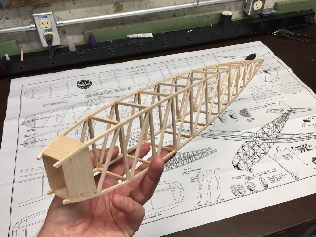
First fuselage side pinned down and glued.
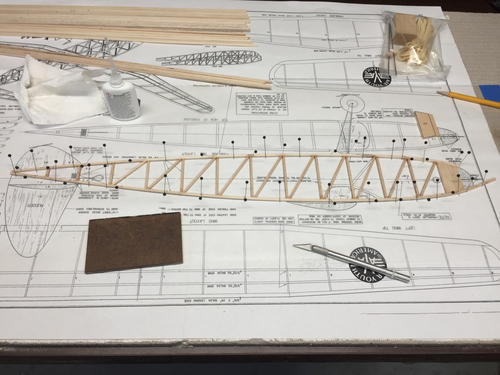
IMG_2917.JPG


I'll be taking my time, enjoying the build and post here as the project progresses.

Jon
 
Last edited:

TooJung2Die

Master member
Finished the second side of the fuselage tonight. Here are both sides laid one on top of the other. I'm eliminating all the rubber motor reinforcements. Not needed. No cabin window frames either. I want to use some sort of jig to keep the fuse straight and square when joining the two sides. In the past I've aligned by eyeball but this is longer than any box fuselage I've built before. A jig would be helpful. I have lots of foam board. Does anyone have an easy temporary fuse jig plan?

IMG_2920.JPG


Jon
 
Last edited:

rockyboy

Skill Collector
Mentor
Nice clean building! :D

I use some wood triangles on stubby bases as movable jigs for keeping the fuse straight - no reason those couldn't be replicated with foam board too. RetroRC has some nice jigs for sale and inspiration too (I have a bunch of Bill's Fingers and Thumbs) http://retrorc.us.com/buildingjigsystem.aspx
 

TooJung2Die

Master member
Thanks, Rockyboy. Work got in the way of progress yesterday. I looked at a lot of fuselage jigs during breaks. Here's what I came up with. I cut a bunch of foam board squares using a carpenter's square. I made a 100% copy of the fuselage top view and covered it with waxed paper. The foam board squares are pinned to the building board. It's working!

IMG_2929.jpg


This may turn out to be the straightest and best aligned fuselage I've ever built.

IMG_2928.jpg


I got less than half the cross pieces finished but I'm tired and that means time to stop for tonight.

Jon
 

TooJung2Die

Master member
Making good headway on what could be a tedious bit, but I enjoy it. Cutting out, shaping and notching all the ribs. It helps to stack the ribs and sand them as a group so they all come out exactly the same. You can make notching saws out of stacked hack saw blades. Two blades = 1/16" notch, three blades = 3/32", etc... I used to cut spar notches with a razor saw until someone in an Old Timers forum showed me his homemade notching saws.

The plans have two spars on the top of the wing and no spars on the bottom. I don't think it will stay that way.

IMG_2934.jpg


Notching saw.

IMG_2630a.jpg


Jon
 
Last edited:

JimCR120

Got Lobstah?
Site Moderator
Maybe too geeky for some but from a math mind standpoint looking at the patterns, symmetry, and uniformity make the blending of math and craftmanship an artful thing. Just saying.
 

Try-n-glide

Active member
Great looking build. Not sure I have developed the patience to accurately cut to just lines. Looking forward to more reports!
 

TooJung2Die

Master member
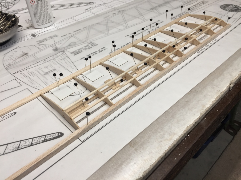
Wing parts are half assembled. It's a little more complicated pinning down an undercamber airfoil than a flat bottom airfoil. It needs shims in the right places to maintain the curved bottom.

IMG_2936.JPG


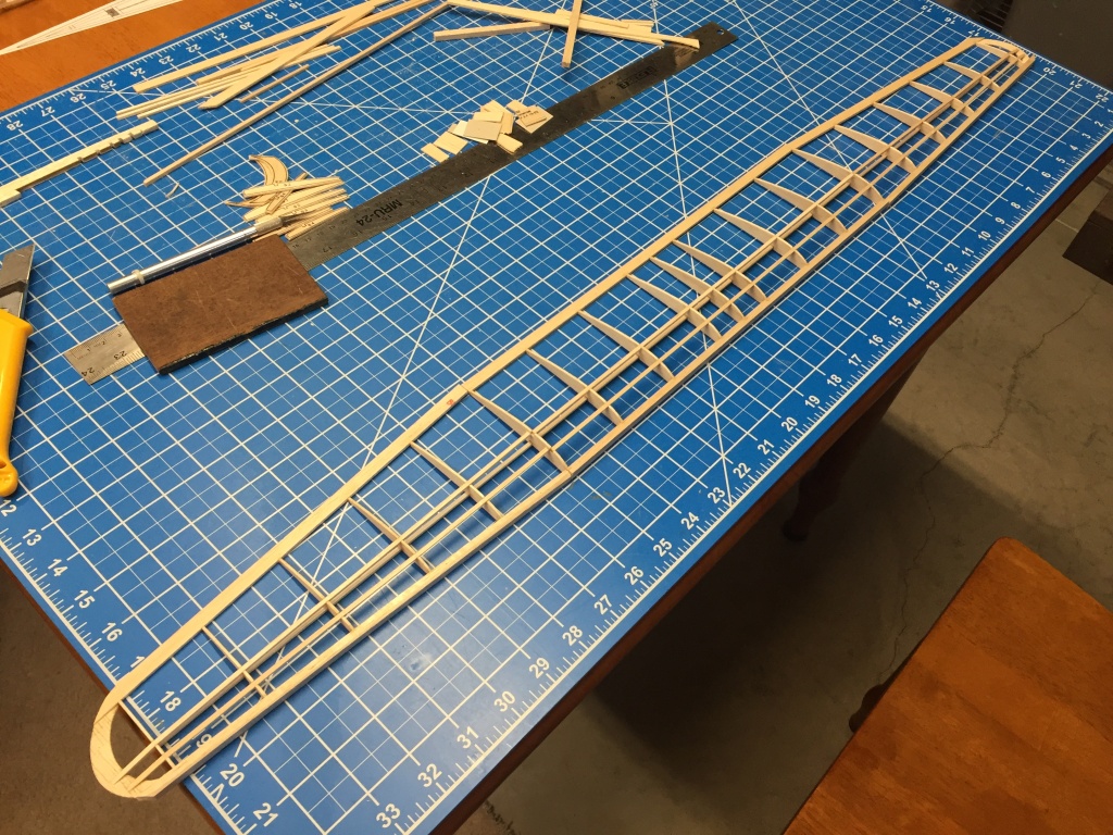
Here are the three wing sections laid out for a view of things to come.

IMG_2943.JPG


Next step, hours of sanding. The rectangular leading edge and trailing edge have to be shaped to blend into the ribs. You can see the bottom spar I added. It didn't look right without it and it'll give the covering film more to stick to on the bottom. I think this wing relies on the thick leading edge for most of it's strength. Everything else is very fragile.

IMG_2944.JPG


Let's make some balsa dust!
Jon
 
Last edited:

TooJung2Die

Master member
The wing is ready to be covered.

IMG_2947.JPG


Gussets added at the polyhedral joints. If this wing folds it won't happen at the joints.

IMG_2948.JPG


The plans called for 3" polyhedral. That might be fine for free flight but for RC it was reduced to 2.5". At this point everything weighs 22 grams.

IMG_2949.JPG


Jon
 
Last edited:

TooJung2Die

Master member
Progress Report. Everything is built so light I don't know why there's a solid balsa vertical stabilizer in the plan. I made a lighter built up vertical stab with a laminated leading edge. For simplicity the horizontal stab has a single side elevator. I don't think the elevator is going to be used much anyway. An airplane like this will be a climb up and glide down flier.

Laminated leading edge.

IMG_2961.jpg


Vertical stab taped in place. The tail feathers need a lot more sanding. Then the control surfaces are cut free.

IMG_2962.jpg


Jon
 
Last edited:

Seahunter

Active member
A very nice build, brings back many memories of my past models reminds me of the old Sparky. I believe Comet made it. Great job. Post a maiden for us.
 

TooJung2Die

Master member
I've been away for a few days of R&R. We had a great time but I couldn't get this airplane off my mind. :) I jumped right in soon after we got back.

The horizontal and vertical stabs are sanded and ready to cover.

IMG_2968.JPG


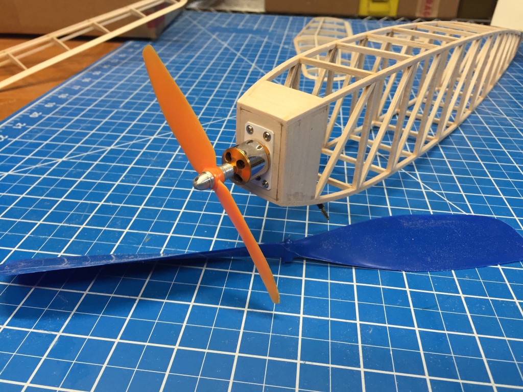
Back to the fuselage. The firewall is 3/32" ply. It has a couple of degrees of down and right thrust. I made a custom motor mount so the motor can be removed from the front. This tiny motor is the first one I bought when I didn't know anything about electric RC. I don't remember exactly what size but it is probably 1510/2200kv. 5x3 is the biggest prop it can handle without overheating. It has surprising thrust for it's diminutive size. I removed it from another airplane with a 40" wingspan for the Contest Commercial. I put the 12" rubber prop in the photo for size comparison.

IMG_2971.JPG


The plan has the landing gear wire lashed to the longerons. That was weak so I made a plywood mount to distribute the stress over more of the fuselage. The wire is sewn and glued to the ply. The landing gear can be much shorter because the electric propeller is less than half the diameter of the rubber prop.

IMG_2973.JPG


Jon
 
Last edited:

TooJung2Die

Master member
Time to start mounting the electronics. It's a good idea to get at least a ball-park accurate idea of where the CG will be so you can move stuff around and achieve optimum CG without adding ballast later. You want the battery to be easy to get in and out. You would like the servos to be accessible too in case one fails and has to be replaced. With the wing moved forward 1" and everything under the wing the CG is at the bottom spar, about 40% from the wing leading edge. This is good because you'd expect the tail to become heavier with the addition of control surface hardware and covering film. The wing will probably be moved back after covering film is on.

IMG_2977.jpg


Jon
 

TooJung2Die

Master member
I began applying the covering film. Applying covering film is my weakest skill. I've had lots of advice and watched lots of videos on how to do it. I just suck at it! When it is really bad I peel it off and try again. At least I haven't broken any spars or ribs on this airplane (so far!). :LOL:

I'm using 1.5 mil document laminating film. It irons on exactly like any other covering film but it is much thinner and lighter. It's much less expensive too. For about $35 I got so much I'll have to leave the leftover to someone in my will. ;) It goes on cloudy and shrinks crystal clear. You wouldn't see it in the photo if there was no reflection.

IMG_2981.JPG


Jon
 
Last edited:

TooJung2Die

Master member
Here is the placement of the electronics. The inside of this fuselage seems huge.

IMG_2985.JPG


We couldn't have the motor all naked like that so a nose was made. It's semi-permanently attached with a couple of small drops of Elmer's Glue. The glue joints can be popped if the motor has to be removed. Covering film will hold the nose securely. I drilled a few holes in the firewall for air to pass through.

IMG_2986.JPG


I'm going to try going old school with the wheels. Hardwood dowels are glued perpendicular to the balsa wheels. Holes for the axles will be drilled in the dowels. Wheels will be turned to shape in my drill press. An o-ring stretched around the circumference will create a tire. We'll see how this idea turns out.

IMG_2987.JPG


Jon
 

rockyboy

Skill Collector
Mentor
Quite the elegant build! :D The nose looks great, and I think the wheels are going to be a hit too.

Where did you get the laminating file from?