You are using an out of date browser. It may not display this or other websites correctly.
You should upgrade or use an alternative browser.
You should upgrade or use an alternative browser.
CustomRCMods Concorde Build Project
- Thread starter CustomRCMods
- Start date
CustomRCMods
Elite member
So, how do you plan on feeding that EDF? A gap in the fuselage, cheater holes (inquiring minds want to know.)
Valid Question, thank you for your interest. I have put a large gap at about 1/3 of the way down the fuse from the nose to make sure I have adequate airflow. It is not Ideal, but hopefully I will be able to make it look good in the end. Suggestions on that would be greatly appreciated as well. I have also played around with cheater holes in the nose area but decided to hold off if I can to preserve the airliner looks. this is my first edf design so I am flying blind for the most part here.
Vimana89
Legendary member
Have you flown delta type planes or anything with elevons before?Valid Question, thank you for your interest. I have put a large gap at about 1/3 of the way down the fuse from the nose to make sure I have adequate airflow. It is not Ideal, but hopefully I will be able to make it look good in the end. Suggestions on that would be greatly appreciated as well. I have also played around with cheater holes in the nose area but decided to hold off if I can to preserve the airliner looks. this is my first edf design so I am flying blind for the most part here.
CustomRCMods
Elite member
Have you flown delta type planes or anything with elevons before?
Yes. I have Flown the FT22, and mini arrow, as well as a custom canard style plane I designed. I am more of a bank and yank pilot by nature, so this plane should be right up my alley
CustomRCMods
Elite member
Bigger motor=more power=more good
True - I need to upscale it a bit to fit the 70mm EDF unit it ordered
CustomRCMods
Elite member
No pictures for this update, but I got the nose on and did some test flights. found the CG pretty far forward, as we thought earlier. unfortunately the fuse took one too many hits and snapped but this is only the 1st model so that’s ok. loaded up the nose with a hardshell 5000mah out of one of my cars and I had great success. now to make the rc version!
CustomRCMods
Elite member
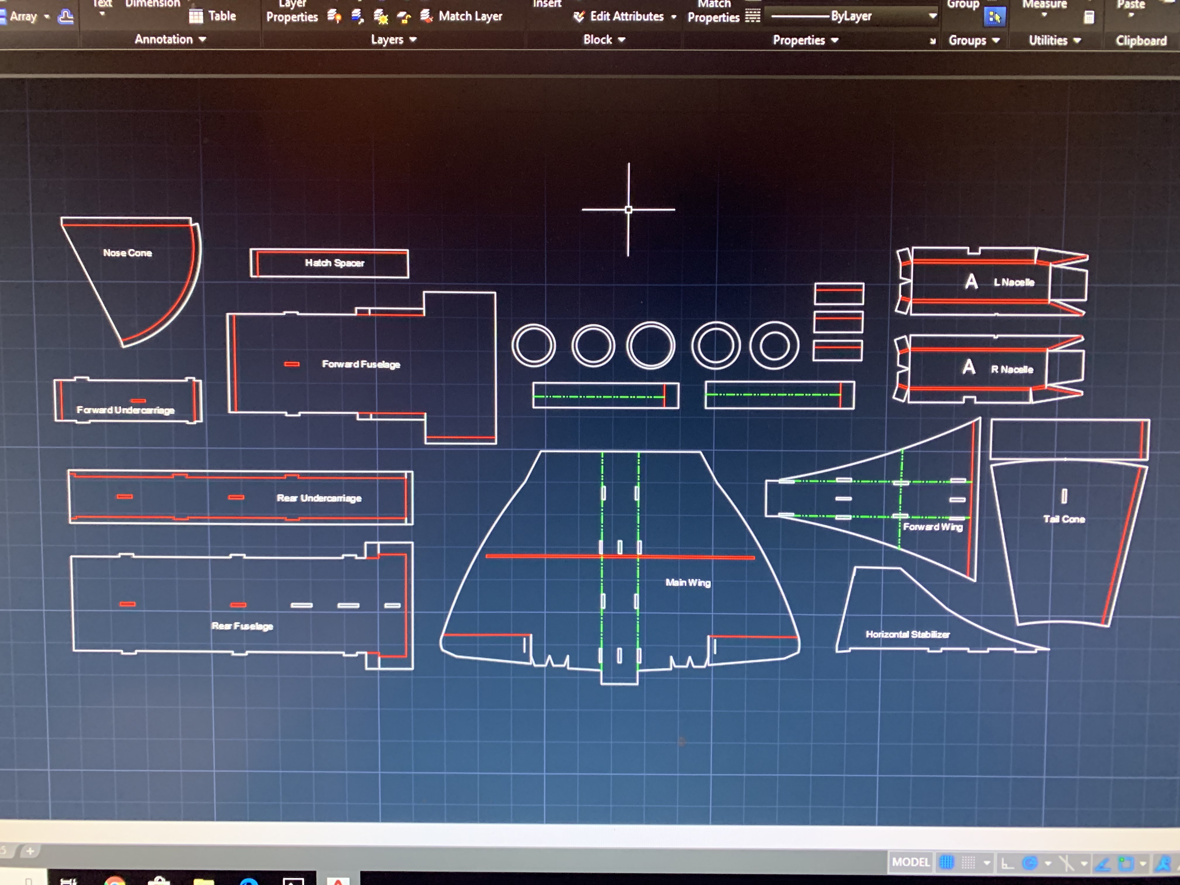
Tonight’s Progress update:
Made necessary changes to the plans, just waiting for the EDF to come in so I can scale the airframe around it. looks like i will need to make over 2 ft long battery/motor cable extensions... that’s fun. Looks like all the parts should be here tomorrow afternoon! Super excited to finally get this thing airworthy! (I say finally although this thread was started less than 48 hours ago because I have been working on these plans for almost a month) All my fuselage and nose qwerks have been resolved and so have my tiling issues. So excited for what’s to come!
Looks like the maiden might fall on sunday if the weather is clear. Any tips on maidening edfs or elevon planes or scratch builds, etc? I have maidened many planes with great success but this one makes me especially nervous 😬😬.
Thanks for your interest in my build and have a great night!

Last edited:
CustomRCMods
Elite member
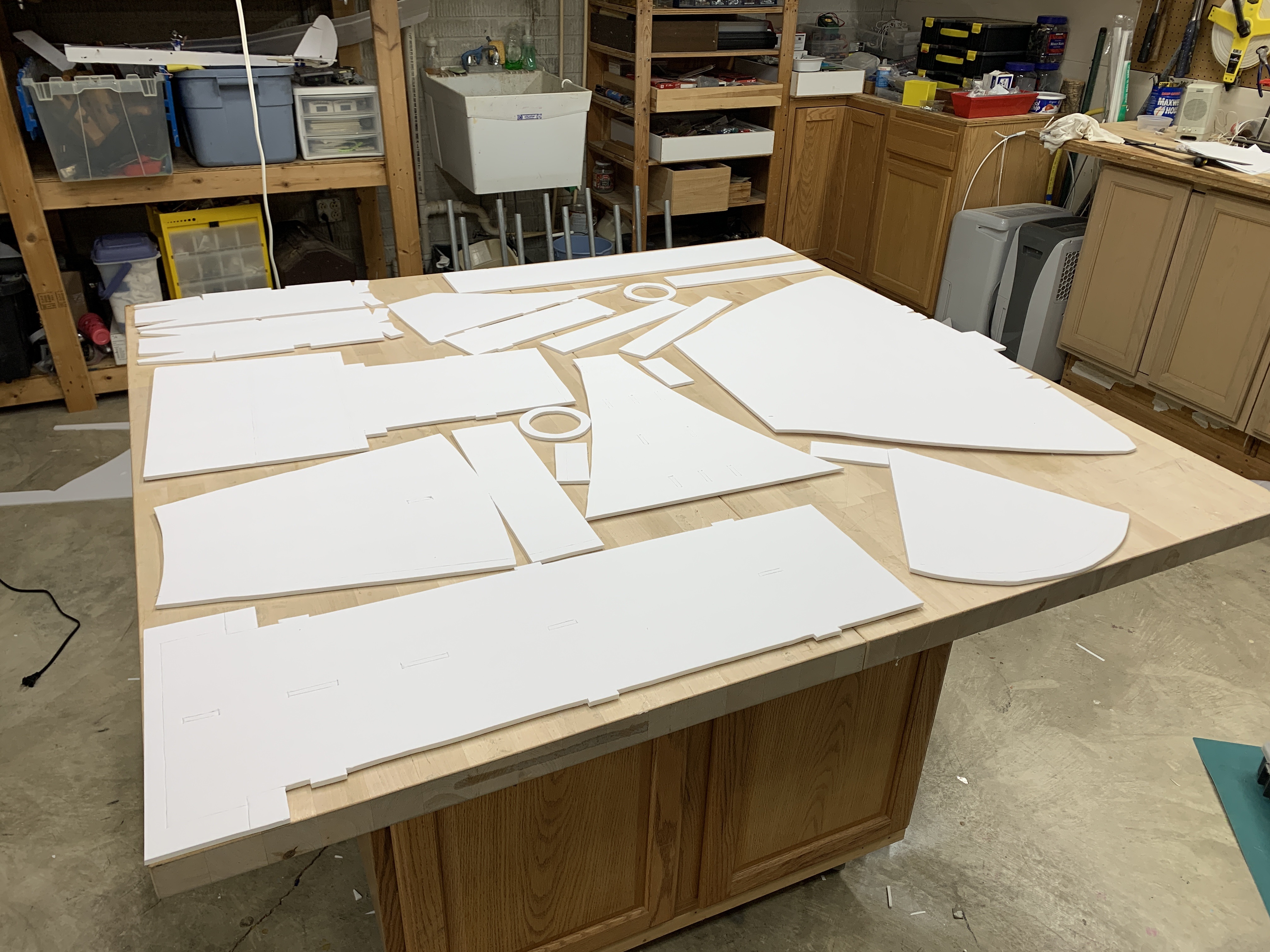
Got another set of parts cut out for the concorde tonight! building tomorrow. Unfortunaltely the EDF and other electronics didn’t come in today, but that’s ok. Just figured the maximum wing size and went for it. Also found the CG was a little farther back than expected. my wing is a little warped unfortunately so I am looking to remedy that as well.

CustomRCMods
Elite member
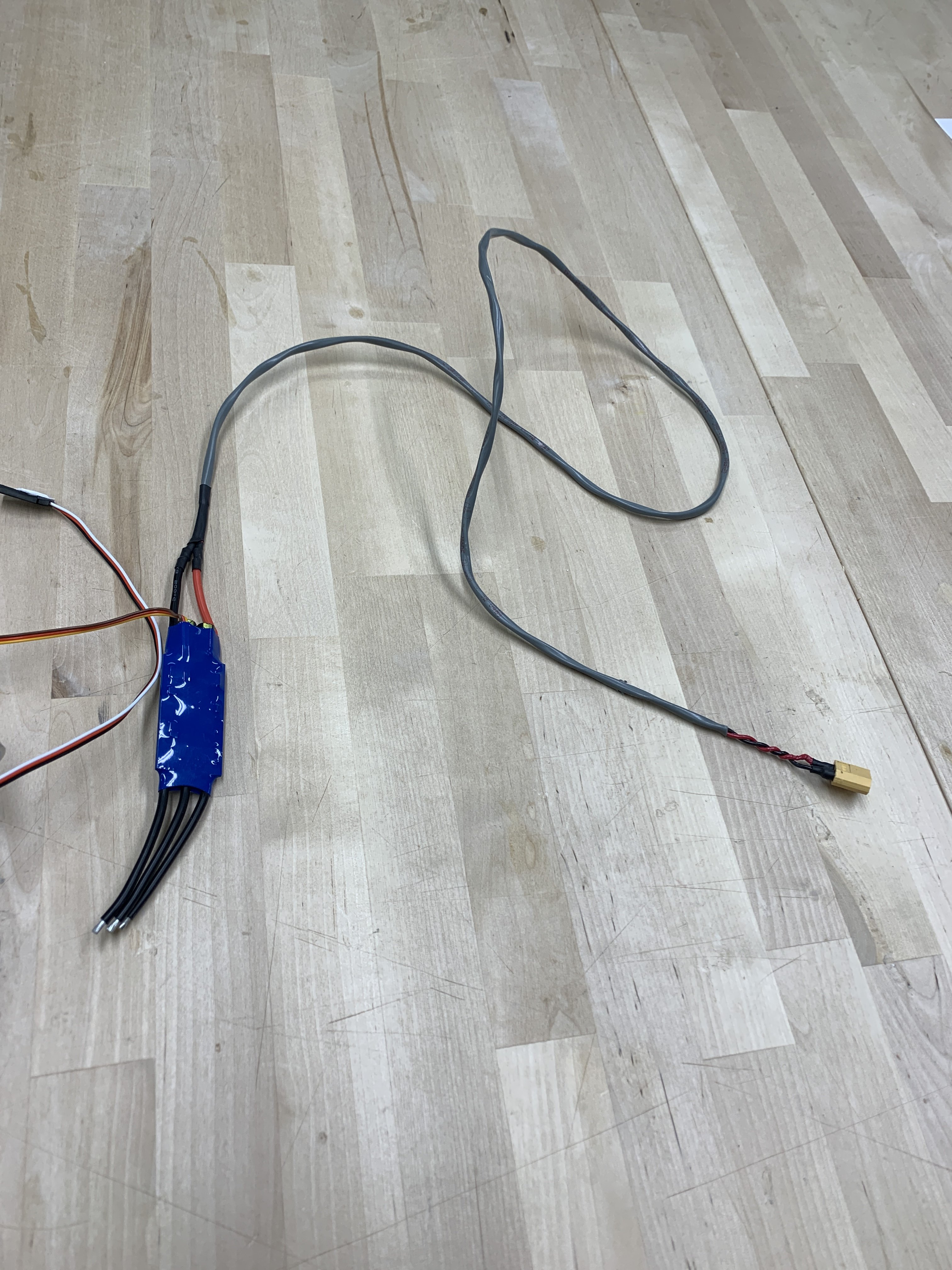
The build of Concorde v2 is just about finished up! still waiting on the edf unit, so final assembly has been postponed yet again. This next version is considerably larger than its predecessor, with a wingspan of 30 inches (1 sheet of foam) and a length well over 6ft long. Still working on an air intake system, would like some advice on what to do. I want great airflow obviously but I would hate to have this beautiful bird look like someone took a hobby knife to the fuselage lol. I also finished off my 3ft long battery lead extension, and I just need the mailman to come already!!!
Anyway, that’s it for tonight’s update. little chance that the package will come tomorrow but who knows...

Anyway, that’s it for tonight’s update. little chance that the package will come tomorrow but who knows...


CustomRCMods
Elite member
Time for another project update:
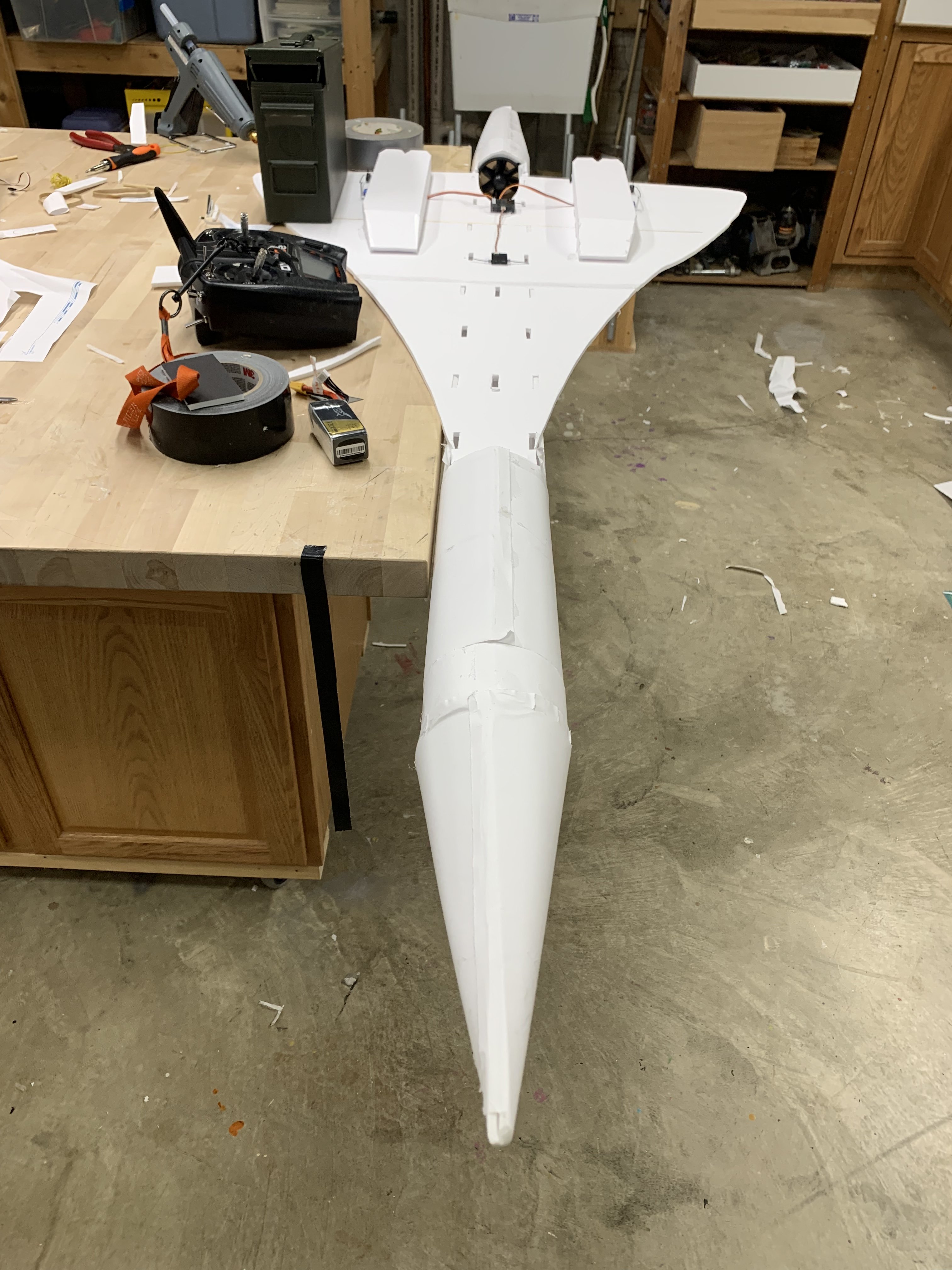
Got the EDF in today and man, does it have a lot of power! I am running a 4s 1300 which seems a little small but that is ok. I went for a 40a esc per the reccomendation of the edf manufacturers and it is running a little warm, even on the bench.
My main issue is the thrust tube setup. I want to maximize power but I literally have no idea or prior knowledge of anything related to EDFs or thrust tubes. My current tube is a 15in long cone that tapers from ~3.75 inches to 2 inches in diameter. Please Help! If it is a quick fix, we might be looking at a maiden tomorrow!
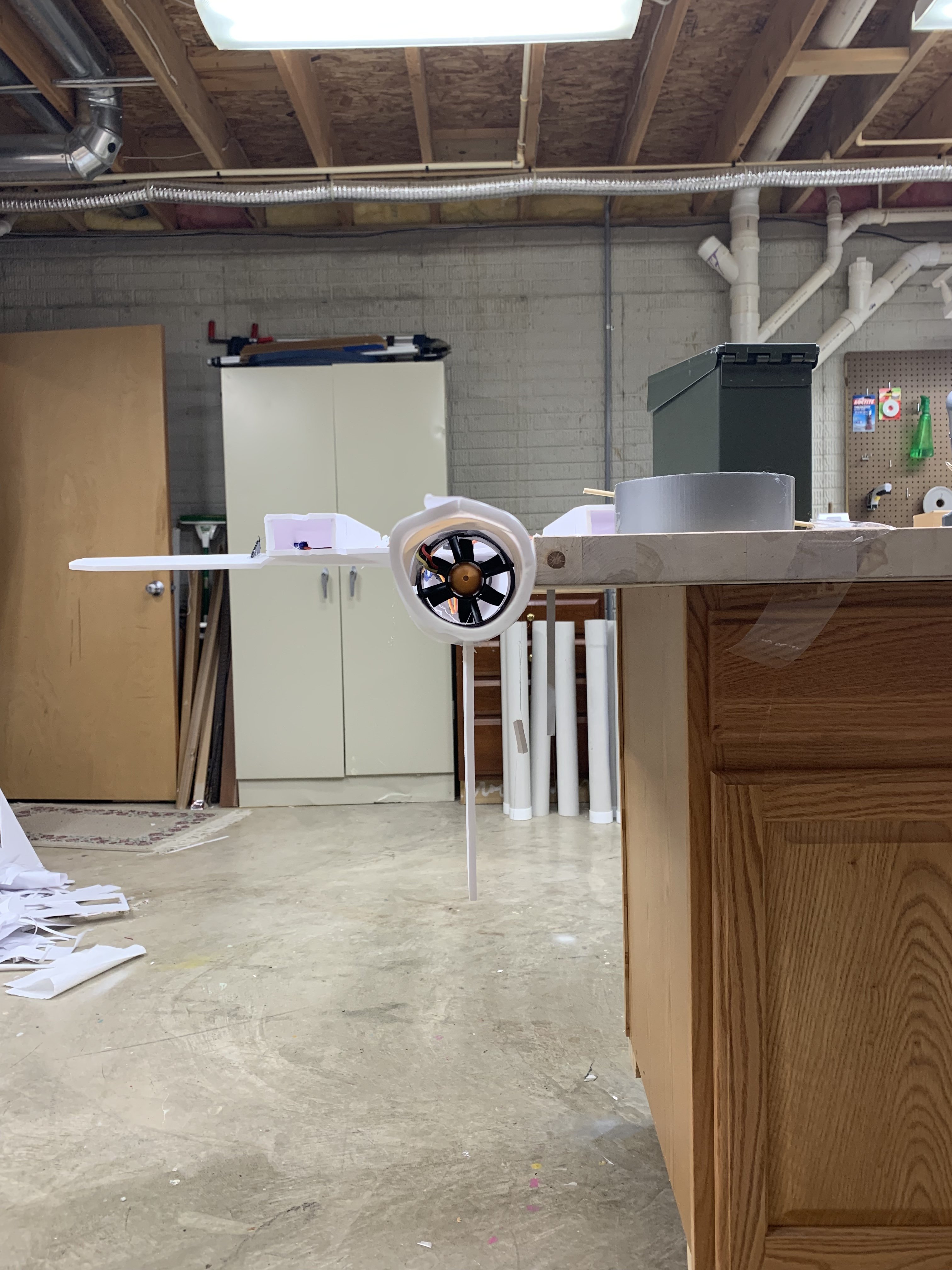
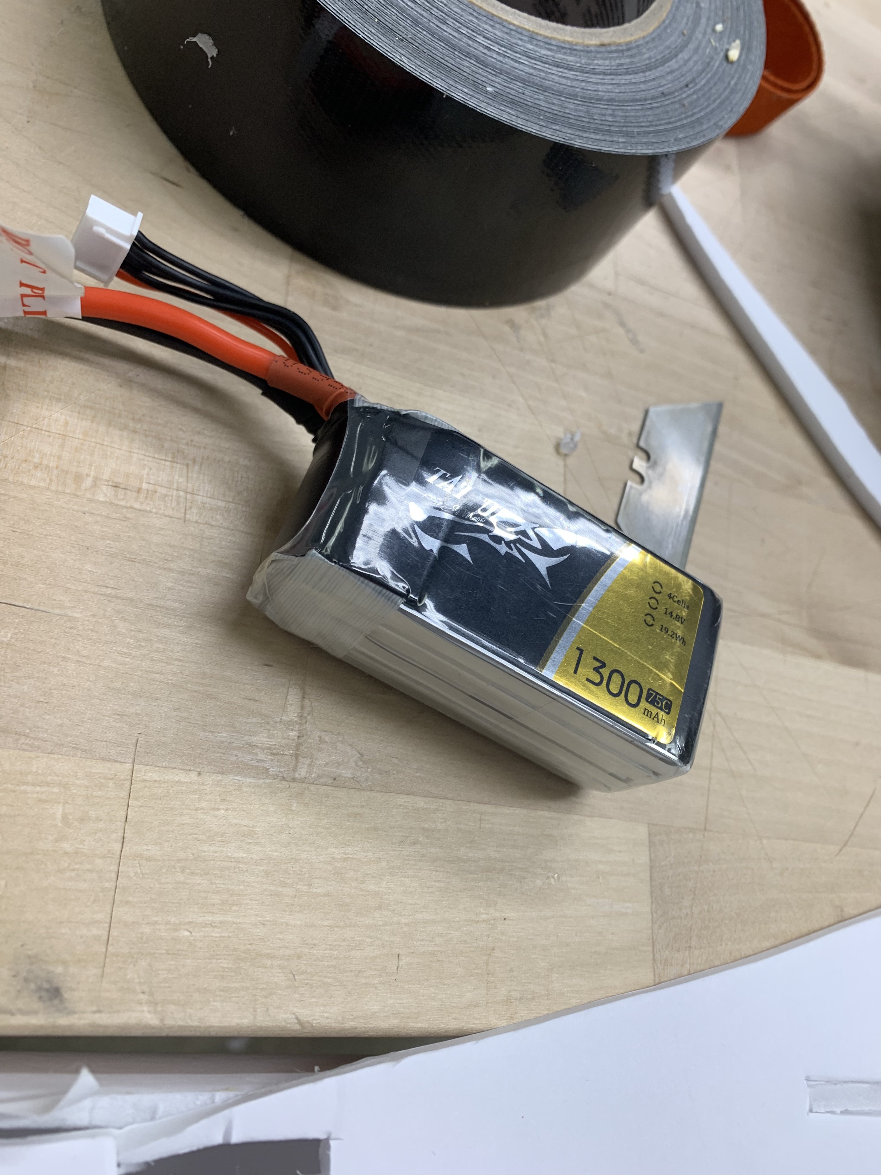


Vimana89
Legendary member
Others more versed in EDF setups will fill in the finer details, but as somebody who may use them in the future, I know that: You want 5-15% reduction in diameter at the exit hole from the part where your EDF is. If you want more static thrust for easier launches and whatnot, go with closer to 5%. If you want higher top end speed but less static thrust, go with a more drastic reduction, up to 15%.Time for another project update:
Got the EDF in today and man, does it have a lot of power! I am running a 4s 1300 which seems a little small but that is ok. I went for a 40a esc per the reccomendation of the edf manufacturers and it is running a little warm, even on the bench.
My main issue is the thrust tube setup. I want to maximize power but I literally have no idea or prior knowledge of anything related to EDFs or thrust tubes. My current tube is a 15in long cone that tapers from ~3.75 inches to 2 inches in diameter. Please Help! If it is a quick fix, we might be looking at a maiden tomorrow! View attachment 126206 View attachment 126207 View attachment 126208 View attachment 126209
I heard that the best length for a thrust tube is 4x the diameter of your EDF unit. A short thrust tube is preferable to no thrust tube. Too long and you probably start losing a bit of performance.
Last edited:
CustomRCMods
Elite member
Others more versed in EDF setups will fill in the finer details, but as somebody who may use them in the future, I know that: You want 5-15% reduction in diameter at the exit hole from the part where your EDF is. If you want more static thrust for easier launches and whatnot, go with closer to 5%. If you want higher top end speed but less static thrust, to with a more drastic reduction, up to 15%.
I heard that the best length for a thrust tube is 4x the diameter of your EDF unit. A short thrust tube is preferable to no thrust tube. Too long and you probably start losing a bit of performance.
Thanks so much for the insight. I definitely need the static thrust on this one so looks like I will be trimming about 1/2 of it off. My original thrust tube looked to be almost a 50% reduction, way too much.
Any ESC Cooling ideas?
Thanks for the help!
JTarmstr
Elite member
Time for another project update:
Got the EDF in today and man, does it have a lot of power! I am running a 4s 1300 which seems a little small but that is ok. I went for a 40a esc per the reccomendation of the edf manufacturers and it is running a little warm, even on the bench.
My main issue is the thrust tube setup. I want to maximize power but I literally have no idea or prior knowledge of anything related to EDFs or thrust tubes. My current tube is a 15in long cone that tapers from ~3.75 inches to 2 inches in diameter. Please Help! If it is a quick fix, we might be looking at a maiden tomorrow! View attachment 126206 View attachment 126207 View attachment 126208 View attachment 126209
I think for a thrust tube you want 85-80% So 3 to 2.75 inches at the end of the tube.
CustomRCMods
Elite member
I don't know a thing about ESC cooling. For air flow, I would suppose you could put it behind your intakes, cheater holes in the path of the air getting sucked into the EDF, but not really obstructing it like taped along the wall.
Alright. I will leave it as is for the maiden and check back on it afterwards. Thanks for the help!
CustomRCMods
Elite member
I think for a thrust tube you want 85-80% So 3 to 2.75 inches at the end of the tube.
Thanks! I will look into those numbers
Pieliker96
Elite member
As long as the ESC is exposed to airflow it should be pretty much fine. If thermal problems do arise then cutting the heat shrink off to allow direct airflow to the PCB is always an option.
As a general rule to maximize static thrust, the outlet area of the EDF should be the same as the "Fan swept area" or FSA - that is, the outlet is 100% of the FSA. Reducing the output diameter reduces the FSA, which decreases static thrust but increases efflux velocity, meaning a higher top speed but less acceleration.
The FSA is computed simply by the total disk area of the fan (pi * fan radius ^ 2) minus the hub area (pi * hub radius ^ 2), the stuff taken up by the spinner and motor. Multiply this by the desired % FSA (in decimal form, e.g. 90% = 0.9). Divide this by pi then take the square root of it to get the output diameter.
I've heard that tube length matters, although I don't really know where that comes from. In my limited testing with a 70mm 10-blade freewing unit on 4s, I lost around 100g of thrust (1600g -> 1500g) by adding any sort of exhaust tube. Maximum static thrust was achieved at 100% FSA, as expected. Thrust dropped off by another 100g upon reduction to 88% FSA, and dropped to 1300g (200 down from 100%) at 85% FSA - this is where the static thrust really started to drop off on my specific fan.
Personally I would recommend sticking to 100% FSA to be on the safe side and then constricting it if further performance is needed. Different fans have different characteristics when restricted in output, but 100% FSA (should, at least) give the most static thrust.
Last edited:
CustomRCMods
Elite member
As long as the ESC is exposed to airflow it should be pretty much fine.
As a general rule to maximize static thrust, the outlet area of the EDF should be the same as the "Fan swept area" or FSA - that is, the outlet is 100% of the FSA. Reducing the output diameter reduces the FSA, which decreases static thrust but increases efflux velocity, meaning a higher top speed but less acceleration.
The FSA is computed simply by the total disk area of the fan (pi * fan radius ^ 2) minus the hub area (pi * hub radius ^ 2), the stuff taken up by the spinner and motor. Multiply this by the desired % FSA (in decimal form, e.g. 90% = 0.9). Divide this by pi then take the square root of it to get the output diameter.
I've heard that tube length matters, although I don't really know where that comes from. In my limited testing with a 70mm 10-blade freewing unit on 4s, I lost around 100g of thrust (1600g -> 1500g) by adding any sort of exhaust tube. Maximum static thrust was achieved at 100% FSA, as expected. Thrust dropped off by another 100g upon reduction to 88% FSA, and dropped to 1300g (200 down from 100%) at 85% FSA - this is where the static thrust really started to drop off on my specific fan.
Personally I would recommend sticking to 100% FSA to be on the safe side and then constricting it if further performance is needed.
Thanks For the thorough explanation. that really makes sense now. For such a large aircraft, Maximizing static thrust is a good idea. I will go for that. Thanks!
Oh btw, in other news, I made an amazing breakthrough in RC technology when attempting a hi-start my FT simple soarer in 40mph wind. This revolutionary breakthrough increases portability by an infinite amount. check it out:
Before:

After:
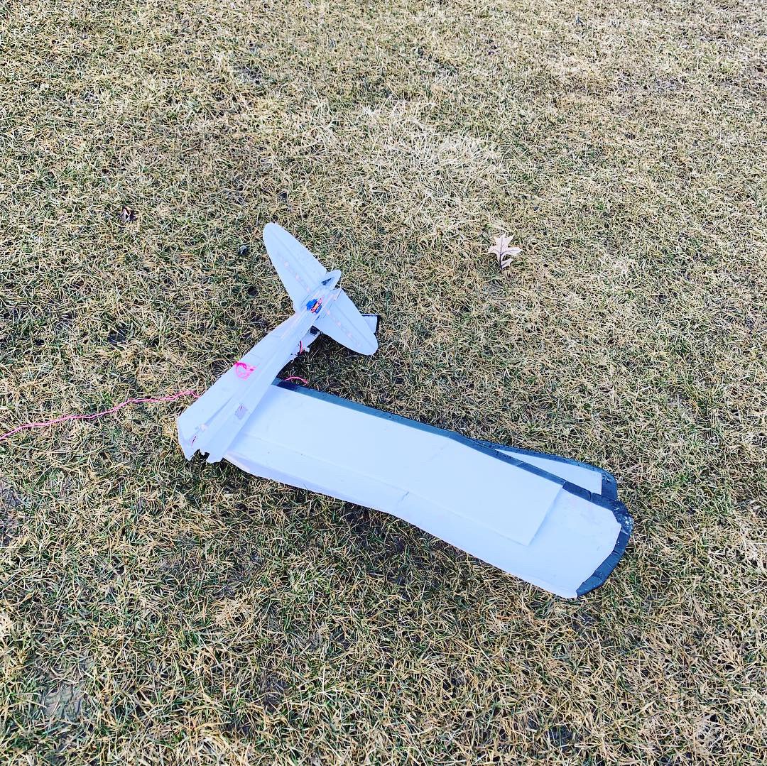
CustomRCMods
Elite member
Just Following up to say that the necessary adjustments were made, and everything straightened out. Thanks to all who helped!
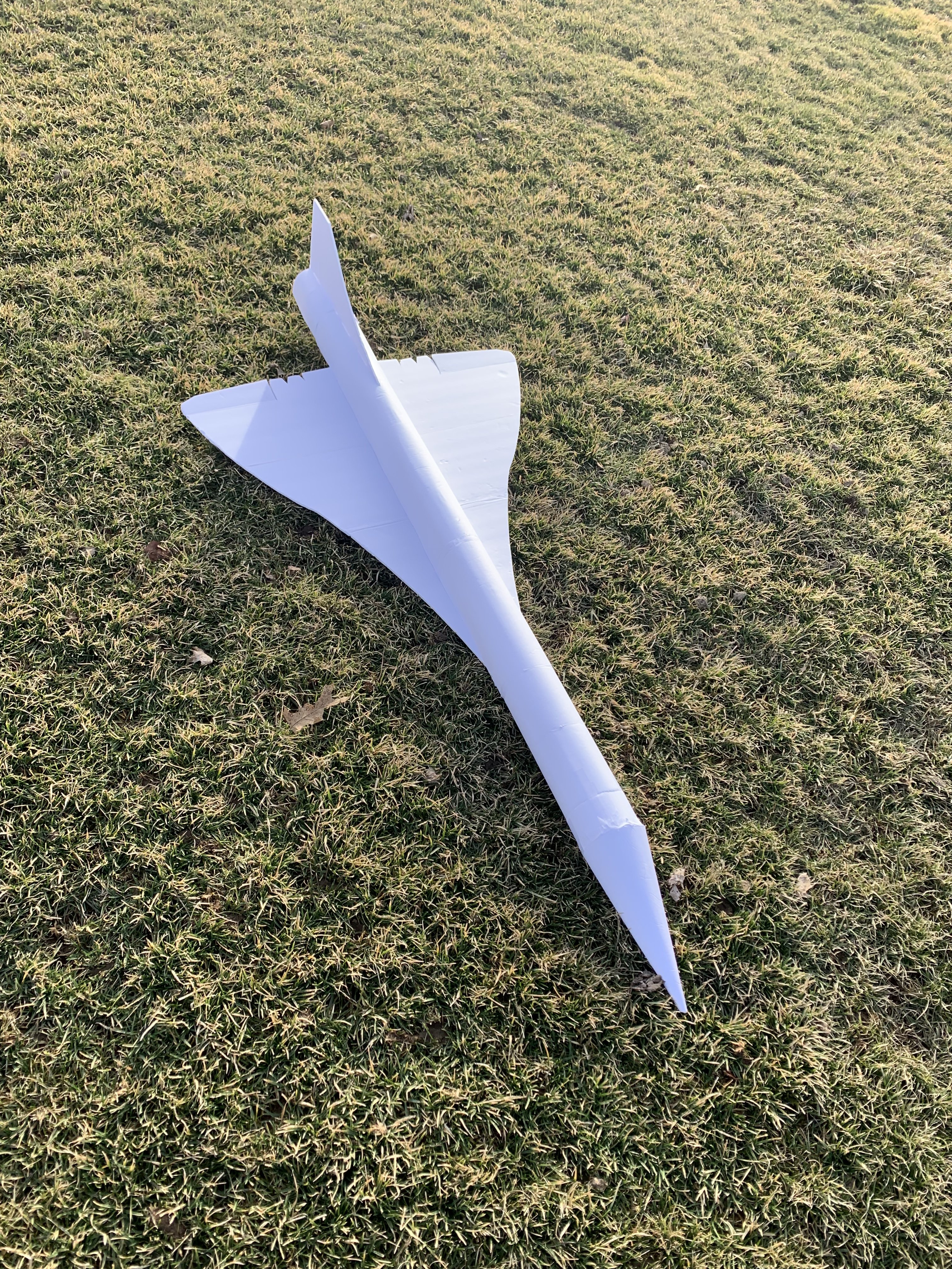
With nice weather today and an airworthy craft, I decided to take it out for a maiden....
It flew amazing!! much better than I ever expected. With the large airframe that has lots of drag, as well as the short and wide thrust tube, it was a very slow flyer but quite maneuverable nonetheless. very snappy on the roll axis but due to the long length the elevator seemed a little sluggish. took it back up with less noseweight and more elevator throws and it is now completely dialed in. I was able to high alpha very easy, and still get the nose down for higher speed passes. Landing of course was a breeze, coming in slow and flaring at the last second.
Overall, I am so happy how this project turned out and very excited to see other members of the community build one.
But I am not done yet....
First, I need to update the plans with my adjustments made, and configure them for more seamless tiling.
Next, I need to build another Airframe off the plans and ensure that It is everything I ever hoped it would be.
Next, I need to shoot a ‘build tips’ video for my channel so that people can understand how it goes together without watching me build the entire thing for hours on end.
Then, I need to get a bunch of flight footage to make content from.
Finally the plans will be posted here and hopefully this thread will turn into a place where people who build this design can share their experiences.
Thank you again to everyone who helped me out on this build, it wouldn’t have taken off without you.

Similar threads
- Replies
- 34
- Views
- 1K
- Replies
- 6
- Views
- 364
