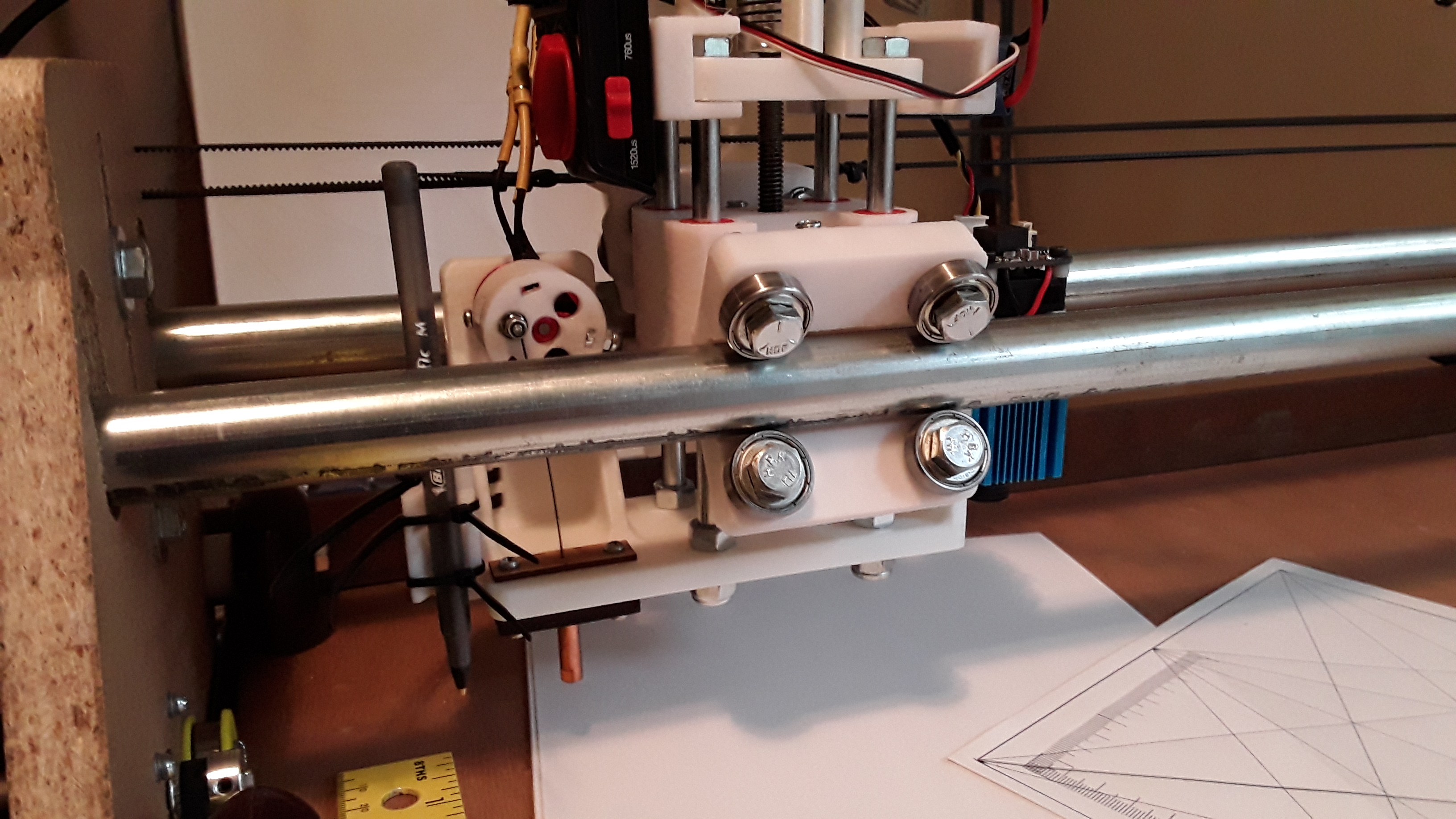
Cutting foam sheets... with a needle!

dkj4linux

Elite member
Just when I think I am ready to cut out a new plane, I keep breaking needles. I have tried the needle keeper like Mobeast and the wire around the bearing like David and Jason. Each time I set my rpm to around 6000 rpms and let the machine just run without the needle even touching the foam board. Around 5 min of running the needle will break, so far I have tried different motors, motor mounts, esc's with no luck. Last night I think I found my problem, I think I have a faulty servo tester. Using my tach, I took constant readings that went from 12000 rpm's to the motor just bumping, without touching the dial. I then pecked the servo tester and the motor started again. The servo tester View attachment 133468 that I am using is a inexpensive one that I purchased from Amazon. Does anyone know of a better option or a more reliable servo tester or did I just get a dud.​

Are you using a tach to get your rpms? Picture of your cutter and details about how it's set up would help... motor, voltage, etc. Also, 12000 rpm will almost always result in bad stuff happening. ESC are very non-linear... i.e. with a 1000kv motor and 12v, you should see 11k-12k rpms at full throttle (servo tester max on dial). BUT it will pass through 6000-8000 rpm before you get more then 1/4 or 1/3 on the servo tester dial. The dial is linear and is usually pretty accurate when exercising a servo... but as a motor control, not so. Stay near the lower end... and I highly recommend getting a digital laser tachometer if you don't already have one... this is the one I have.

Also, watch where I use the tach and adjust the servo tester in this video... I'm not rotating the knob very far at all to get 8000 rpm. Turn down the sound :eek:


-- David
 

dkj4linux

Elite member
Thanks, Rockyboy.

I've never heard about such a thing... so wasn't aware of it. While that would be neat, for this application, that's probably overkill IMHO. Once the proper/desired cutter rpms have been determined using the tach, it seems a pretty easy thing to simply mark/remember where on the servo tester's dial that setting is... and then simply go straight to it for successive runs. An exact RPM reading really isn't necessary (I shoot for ~8000 rpm, no load) and a couple hundred rpms either way isn't going to hurt... you simply want the lowest RPM setting that gives acceptable perforations/mm and cleanest cuts at an acceptable feed rate (in my experience, 10-15 perforations/mm for DTFB). That should also result in the least stress and longest life for the cutter/needle.

In the video I referenced, I took far longer to start the job as I was demonstrating a few things... in actuality, it takes less than a minute to switch on the vacuum, move the tool head to desired X/Y start, start the cutter and set speed to a mark on the dial, lower Z to material surface, and then start the job. My gcode always has a G92 X0 Y0 Z0 in the header so it sets in the current X/Y/Z settings at job start as the origin for all cuts. Not difficult at all...

-- David
 

Snow-B1

Junior Member
Are you using a tach to get your rpms? Picture of your cutter and details about how it's set up would help... motor, voltage, etc. Also, 12000 rpm will almost always result in bad stuff happening. ESC are very non-linear... i.e. with a 1000kv motor and 12v, you should see 11k-12k rpms at full throttle (servo tester max on dial). BUT it will pass through 6000-8000 rpm before you get more then 1/4 or 1/3 on the servo tester dial. The dial is linear and is usually pretty accurate when exercising a servo... but as a motor control, not so. Stay near the lower end... and I highly recommend getting a digital laser tachometer if you don't already have one... this is the one I have.

Also, watch where I use the tach and adjust the servo tester in this video... I'm not rotating the knob very far at all to get 8000 rpm. Turn down the sound :eek:


-- David
Thanks for the help David, I swapped out the servo tester, ESC and motor. I am now getting consistent readings with my digital tachometer. I am not sure which was giving me the problem, but all seems well for now.
 

Toolman45014

Junior Member
Guys, I first saw David's needle cutter on the RC Powers thread and have been following it on 3 forums since. I have been watching my yard carefully for a hairy goriila to come by so that I could offer him bananas in return for building me a CNC. Sadly they seem to be indigenous to TX. Since I have no CAD skills, no engineering skills and limited time due to business obligations I did the only thing that made sense and ordered the Lowrider2 hardware from Ryan at V1.

As I am now printing the 3D parts I was wondering if anyone was aware of a needle cutter mount design that was out there for the LR2. I am going to attempt use the CF2822 design that David has developed but am struggling to figure out how to adapt it to attach to the LR2 611 plate. If anyone is aware of a design for this mount please post where I can find it.

I want to keep the router option so in the future I can cut out wood to make some of the other cool machines you guys are doing, I am looking at you Moebeast.

So whether I ever get this machine working or not I have enjoyed watching the progress you all have shared with us! Thanks!

Tim
 

dkj4linux

Elite member
Guys, I first saw David's needle cutter on the RC Powers thread and have been following it on 3 forums since. I have been watching my yard carefully for a hairy goriila to come by so that I could offer him bananas in return for building me a CNC. Sadly they seem to be indigenous to TX. Since I have no CAD skills, no engineering skills and limited time due to business obligations I did the only thing that made sense and ordered the Lowrider2 hardware from Ryan at V1.

As I am now printing the 3D parts I was wondering if anyone was aware of a needle cutter mount design that was out there for the LR2. I am going to attempt use the CF2822 design that David has developed but am struggling to figure out how to adapt it to attach to the LR2 611 plate. If anyone is aware of a design for this mount please post where I can find it.

I want to keep the router option so in the future I can cut out wood to make some of the other cool machines you guys are doing, I am looking at you Moebeast.

So whether I ever get this machine working or not I have enjoyed watching the progress you all have shared with us! Thanks!

Tim
Thank you, Tim, for the kind words. I thought hairy gorillas were more widespread... but what do I know?

Look back to here... and the following posts for the collaboration between Rockyboy and Jason (jhitesma) on a 611 mount for a LR2 needle cutter. I THINK Rockyboy actually has one working and Jason's design is out on the Onshape site... 611 mount.

Hopefully, one, or both, will chime in to give better information.

Again, thanks for dropping in.... welcome!

-- David
 

rockyboy

Skill Collector
Mentor
Thank you, Tim, for the kind words. I thought hairy gorillas were more widespread... but what do I know?

Look back to here... and the following posts for the collaboration between Rockyboy and Jason (jhitesma) on a 611 mount for a LR2 needle cutter. I THINK Rockyboy actually has one working and Jason's design is out on the Onshape site... 611 mount.

Hopefully, one, or both, will chime in to give better information.

Again, thanks for dropping in.... welcome!

-- David

Yep! @jhitesma 's needle cutter mount design worked great - I'm still using my Lowrider Needle cutter and it hasn't even broken a needle after 6 or 8 planes
 

dkj4linux

Elite member
A bit of digression, some exploration, a dose of boredom, 3dprinter sitting idle, parts on hand, a whim of fancy, and a bit of folly... it's PLAYTIME! Can't nap ALL the time... ;)

Poor FoamRipper. Built originally with Marlin/Mega/RAMPS, I recently took a nostalgic trip back in time to convert it over to LinuxCNC, the control software I started with, way back in my initial forays into CNC. I had used it, along with SketchUp and the Phlatboyz CAM extensions, to create gcode for all the little bluecore fan-fold foam aircraft my late flying/fishing buddy and I flew in my pasture... as well as all the parts for a second CNC machine for him. I really do like LinuxCNC and thoroughly enjoyed developing the inexpensive LinuxCNC interface documented in this thread... but, by today's standards (Marlin/Grbl), it is a bit big and clunky. And since there seems little interest, beyond my own, and my curiosity is now satisfied, it's time to move on to something new...

I've built more than a dozen CNC machines over the past several years and virtually all of them started with Marlin/Mega/RAMPS. Since I had a number of the little board sets that I knew worked, I kept using them. One of the machines still in use, an MPCNC laser engraver, sports a miniRambo board now... having been used to help debug a laser raster-engraving issue in newer versions of Marlin, over on the V1Engineering forum.

Somewhere along the way, however, I picked up a couple of MKS Gen L v1.0 controllers. I don't remember exactly why... other than they were supposedly 100% compatible with the Mega/RAMPS combo I'd been using and was so familiar with.

The digression and exploration... I reverted the FoamRipper to the Marlin/Mega/RAMPS scheme from before. However, I used the MKS Gen L v1.0 board this time. I flashed it with the Marlin/RAMPS firmware from the V1Engineering site and applied the RAMPS "pin44 remap" mod (isolated white wire) and set it up for the full-graphics LCD display.

20190527_084829.jpg


The isolated white and gray wires are the RAMPS "remapped Fan1 to pin 44" mod for TTL laser modulation, using M107 and M106 Sxxx gcodes for control...

20190527_165758.jpg


20190531_112125.jpg


Boredom and fancy... I had thought I might play with putting a laser on the FoamRipper. Pretty useless, really -- diode lasers won't cut foam-board -- but I thought it could be fun to play with as an engraver. So, my compact carriage and Z-lift got a new appendage and became a bit the monstrosity... sporting one of the never-used spare Eleksmaker 2.5 watt laser modules I had on hand. Pen/marker, needle-cutter, and now laser... all mounted on the same carriage together.

20190616_100313.jpg


20190616_121905.jpg


20190616_121954.jpg


20190617_093426.jpg


20190618_133521.jpg


And, in action...


So, it works... but is of dubious value. But it keeps me off the streets and gives me something to do between naps

-- David
 
Last edited:

Chuppster

Well-known member
I'm seriously thinking about jumping on the band wagon here. I've done some reading on this thread but honestly I find it very intimidating to read the whole thing so I'm asking a question that I'm sure has already been answered (sorry!). What's the best software to use to generate Gcode based on a .dxf? I know how to edit the PDF's in Inkscape, but taking the file to a toolpath is what has me puzzled.
 

dkj4linux

Elite member
Welcome, Chuppster! Jump on in :)

Not exactly free -- but not expensive either (~$70) -- is Estlcam. It is very suitable for the home hobbyist and is probably the most popular CAM solution in the MPCNC crowd. Takes in DXF or SVG and spits out gcode for Marlin and Grbl... and is free and uncrippled for a generous trial period. Tons of support and good tutorials over on the V1Engineering forum... good folks there, too!

I've also used a free version of SketchUp and the SketchUCAM extensions to generate gcode for many RC foamy aircraft.

Inkscape with the JTech laser plugin is also great for generating laser gcode.

What firmware and tools are you going to use? What are you primarily interested in CNC'ing?

-- David
 

Chuppster

Well-known member
Welcome, Chuppster! Jump on in :)

Not exactly free -- but not expensive either (~$70) -- is Estlcam. It is very suitable for the home hobbyist and is probably the most popular CAM solution in the MPCNC crowd. Takes in DXF or SVG and spits out gcode for Marlin and Grbl... and is free and uncrippled for a generous trial period. Tons of support and good tutorials over on the V1Engineering forum... good folks there, too!

I've also used a free version of SketchUp and the SketchUCAM extensions to generate gcode for many RC foamy aircraft.

Inkscape with the JTech laser plugin is also great for generating laser gcode.

What firmware and tools are you going to use? What are you primarily interested in CNC'ing?

-- David

A little of my background, I'm a computer engineer currently doing firmware development, so I love playing with my 3d printers. I'm no stranger to Marlin and I hope to use that, but I'm open to other options if Marlin isn't the best for this application.

My primary interest is foam cutting. I love the simplicity of the needle, and I have most of the stuff for that head lying around. I've built enough DTFB aircraft that I'm getting tired of leaning over the bench with an exacto.. haha! A secondary use would be balsa and thin ply. I love building with balsa when I can afford it. I have access to a very well stocked tool room at work for my metal needs so I don't think I'll need to support aluminum.

I was hoping to use Fusion 360 but I can't seem to figure it out (using a .dxf of Flite Test plans). I've done gobs of 3d modeling in it and I know it can do toolpaths but this is my first time trying to do such a thing. I'd be willing to pay for Estlcam but something inside of me gravitates towards freeware whenever possible. I guess I'm a bit stingy.
 

jhitesma

Some guy in the desert
Mentor
It is possible to use Fusion360, but I found it to be way more work than ESTLCAM. I haven't tried using Fusion for CAM in awhile but what I found was:

The MPCNC post-processor situation was confusing. No definitive answer as to which version was most current, some older versions apparently did some things better than newer versions, different forks some of which looked better...but weren't still maintained. And just figuring out how to add the post-processor on mac (the only computer I had at the time which ran Fusion reasonably well) was a major pain.

Even setting aside the post-processor situation I found Fusion's CAM to be more difficult to work with. More powerful for sure, but just getting setup was more work since you had to define the workpiece, and then importing the DXF wasn't as straightforward, and selecting parts of it for different types of cuts weren't as straightforward. Now, I'm sure a lot of that would get better with experience as I was very much finding my way around still....but all of the Fusion CAM tutorials I found were way more advanced and didn't really address the type of cuts we need. So there may have been simple answers I just wasn't finding or aware of.

And for me the deciding factors were - Fusion just doesn't run well on the computer in my shop that I use for CAM. And I already had ESTLCAM since I was able to get up and running with it so quickly and easily - so I didn't have much incentive to keep figuring out Fusion.

I kind of want to look into it again though since I've got a newer PC now that does run Fusion well and due to OnShape's license changes I'm trying to switch to using Fusion for more of what I used to use OnShape for. (I also joined the EAA and have a fee solidworks license from that now but it doesn't run on mac at all and I still do a lot from my macbook so I'm not huge on diving in too deeply to solidworks. Though I did see a discussion on the MPCNC FB page yesterday about solidworks having a free maker license now and that it includes a CAM package as well so I'm tempted to give it another look.) If the post-processor situation has improved since last time I tried Fusion then I probably will give it another try. I had Estlcam running on my macbook through wine...but it appears to have stopped working after a recent macos update for some reason and I haven't dug into figuring out why...so that does give me a bit more incentive to try and get Fusion going for CAM.

I really do like estlcam though. I was going to say the price has gone up...but I just checked and it's $60 right now...so either it was less than that when I bought it or it's gone back down :D Either way I'm a huge fan of free software as well but still felt estlcam was worth it. Not only is it simple and easy to use as well as quick for what we do (It normally takes me about 20 minutes to prepare one sheet of FT plans for cutting - but that can vary considerably depending on how many parts and what type of cuts are on the page) but the author is also supportive and helpful. He takes part in the MPCNC forums and has made several changes to the software based on feedback from MPCNC users. So I didn't mind supporting him back at all in this case.

If you do get Fusions CAM figured out I'd love to hear the details about which post-processor you used, how you set things up, and any tricks you found to making it quick to generate the toolpaths!
 

Chuppster

Well-known member
It is possible to use Fusion360, but I found it to be way more work than ESTLCAM. I haven't tried using Fusion for CAM in awhile but what I found was:

The MPCNC post-processor situation was confusing. No definitive answer as to which version was most current, some older versions apparently did some things better than newer versions, different forks some of which looked better...but weren't still maintained. And just figuring out how to add the post-processor on mac (the only computer I had at the time which ran Fusion reasonably well) was a major pain.

Even setting aside the post-processor situation I found Fusion's CAM to be more difficult to work with. More powerful for sure, but just getting setup was more work since you had to define the workpiece, and then importing the DXF wasn't as straightforward, and selecting parts of it for different types of cuts weren't as straightforward. Now, I'm sure a lot of that would get better with experience as I was very much finding my way around still....but all of the Fusion CAM tutorials I found were way more advanced and didn't really address the type of cuts we need. So there may have been simple answers I just wasn't finding or aware of.

And for me the deciding factors were - Fusion just doesn't run well on the computer in my shop that I use for CAM. And I already had ESTLCAM since I was able to get up and running with it so quickly and easily - so I didn't have much incentive to keep figuring out Fusion.

I kind of want to look into it again though since I've got a newer PC now that does run Fusion well and due to OnShape's license changes I'm trying to switch to using Fusion for more of what I used to use OnShape for. (I also joined the EAA and have a fee solidworks license from that now but it doesn't run on mac at all and I still do a lot from my macbook so I'm not huge on diving in too deeply to solidworks. Though I did see a discussion on the MPCNC FB page yesterday about solidworks having a free maker license now and that it includes a CAM package as well so I'm tempted to give it another look.) If the post-processor situation has improved since last time I tried Fusion then I probably will give it another try. I had Estlcam running on my macbook through wine...but it appears to have stopped working after a recent macos update for some reason and I haven't dug into figuring out why...so that does give me a bit more incentive to try and get Fusion going for CAM.

I really do like estlcam though. I was going to say the price has gone up...but I just checked and it's $60 right now...so either it was less than that when I bought it or it's gone back down :D Either way I'm a huge fan of free software as well but still felt estlcam was worth it. Not only is it simple and easy to use as well as quick for what we do (It normally takes me about 20 minutes to prepare one sheet of FT plans for cutting - but that can vary considerably depending on how many parts and what type of cuts are on the page) but the author is also supportive and helpful. He takes part in the MPCNC forums and has made several changes to the software based on feedback from MPCNC users. So I didn't mind supporting him back at all in this case.

If you do get Fusions CAM figured out I'd love to hear the details about which post-processor you used, how you set things up, and any tricks you found to making it quick to generate the toolpaths!

Okay, I'll toy around with it some more. I'm in the process of sourcing parts, very exciting!
 

Chuppster

Well-known member
I see people using bearings to guide their needle on their needle cutters. Has this been found to be beneficial, or does it work just as well to go straight into the tip?
 

jhitesma

Some guy in the desert
Mentor
In general some kind of guide does seem to be helpful. I like the bearings and use them. David (dkj4linux) has had good luck with oiled wooden guides of various styles.

The guides help the needle bend along a longer area spreading the forces instead of concentrating them in one area. This can potentially help prevent breakage (though I'm not sure anyone has seen breakage down low on the needle where it bends going into the tip.) but mostly it seems to help the needle run cooler since there's less friction from the needle rubbing against the sides of the tip. So while the guides themselves do add some additional friction they appear to overall lower friction by letting the needle deflect over more of its length.
 

Keno

Well-known member
In general some kind of guide does seem to be helpful. I like the bearings and use them. David (dkj4linux) has had good luck with oiled wooden guides of various styles.

The guides help the needle bend along a longer area spreading the forces instead of concentrating them in one area. This can potentially help prevent breakage (though I'm not sure anyone has seen breakage down low on the needle where it bends going into the tip.) but mostly it seems to help the needle run cooler since there's less friction from the needle rubbing against the sides of the tip. So while the guides themselves do add some additional friction they appear to overall lower friction by letting the needle deflect over more of its length.
Thanks guys, working on it.
 

dkj4linux

Elite member
In general some kind of guide does seem to be helpful. I like the bearings and use them. David (dkj4linux) has had good luck with oiled wooden guides of various styles.

The guides help the needle bend along a longer area spreading the forces instead of concentrating them in one area. This can potentially help prevent breakage (though I'm not sure anyone has seen breakage down low on the needle where it bends going into the tip.) but mostly it seems to help the needle run cooler since there's less friction from the needle rubbing against the sides of the tip. So while the guides themselves do add some additional friction they appear to overall lower friction by letting the needle deflect over more of its length.

I believe Jason's explanation of what is going with the pre-guides here is entirely correct. Further, I believe the Mig welding tip, which is our "main guide", with its relatively large thermal mass and its proximity to the needle point and the material being cut, is likely going to be the culprit with most heat-related foam-cutting issues.

In my thinking and experience -- without pre-guides of some sort -- the flexing needle enters the Mig-welding tip, bends as it can within the bore, and then exits the tip... all with considerable friction and the resultant buildup of heat. If it gets hot enough -- and it will, if something isn't done to control it -- some heat is transferred to the business end of the needle and the foam it contacts, and the localized heating will eventually result in melted foam coating the needle, and eventually being drawn up into the tip. Only bad things result... and the cutter and cut quality suffer.

The pre-guides are simply an attempt to move the flexing needle's points of constraint out of the Mig-tip (the main guide) to a point ABOVE it. In constraining the needle's motion to as near straight-line, up-and-down as possible BEFORE it enters the main guide... we hopefully reduce the friction, and generation of heat, to manageable levels.

So, effective pre-guides have at least two points of constraint... an entry at the top and an exit at the bottom. The bearings on Jason's cutter are arranged such that the two upper-most bearings serve as entry constraint and the lower-most bearings, the exit constraint. On my oil-saturated wooden pre-guides, I have upper and lower wooden "plates" (or stacks of plates) with a very small aperture (hole), separated by the thickness of the plastic cutter body platform... and providing the points of constraint. In addition, I most often fill the area between the upper and lower guides with packed cotton, which is saturated with light machine oil, and helps lubricate and stabilize any erratic motion of the needle.

Alternatively, you could simply do away with the pre-guides and direct a flow of air at the Mig-welding tip, sufficient to keep it cool... similar to the part-cooling fan on a 3d printer. Fins are sometimes added to the tip as well... to increase the surface area. Another possibility is to use a main guide that doesn't have the thermal mass the Mig-tip does. The sports-ball inflation needles used on early cutter seemed to stay cooler far better... but it isn't as robust and long-lasting. Another thought I've kicked around -- but not yet tried -- is using the wooden stack idea to build a non-metallic main guide. And, there is at least one person I know of that has used a teflon/nylon/? tip to surprisingly good effect... but I suspect it -- and possibly the wooden-stack -- won't be as robust and long lasting as the Mig-tip.

So, which is better? Since this is all seat-of-the-pants engineering... you decide. Thankfully, the cutter is such a simple and inexpensive mechanism, trial and error methods to sneak up on something that works for you is not out of the question; i.e. YMMV.

Have fun. That is, after all, what DIY is all about... isn't it? ;)

-- David
 

Keno

Well-known member
Thanks all for expressing your opinion and thoughts.

I have had to reprint some of the parts I received and this has slowed my build. Not complaining as the purchase of a 3D printer has been one of my best buy's. Now I have move on to 3D drafting, the learning curve continually reforms itself over and over. Thanks again.
 

mmccoo

New member
Hello all and hello David,

The concept of a needle cutter intrigued me for a long time. I have a working machine and I wanted to share my experiences.

I haven't followed the recent postings and I can't even claim to have read the majority of the older stuff. Still, I've found what I have read to be incredibly interesting. Also, kudos to David on how supporting and positive you are with everyone and every idea. A discouraging word is not just seldom heard. it's not heard at all. My compliments to you.

Here's the video:


Miles