
You are using an out of date browser. It may not display this or other websites correctly.
You should upgrade or use an alternative browser.
You should upgrade or use an alternative browser.
Cutting foam sheets... with a needle!
- Thread starter dkj4linux
- Start date
dkj4linux
Elite member
SIL is very talented... I couldn't get over the fact that you can't tell those are printed figures any more. He's got a couple more to do...cool little groot!
Your laser marking the ceramic is also way cool! Have you tried different paint colors? or is it just the fact that the paint is burnt into the ceramic? I suppose the details on this are in the Lightburn forum?

The ceramic tile thing is real... called the Norton method. Amazingly the image is somehow fused to the ceramic... and even scraping it with metal tools doesn't affect it
If you'll search the LB forum for "@Bulldog" you'll see a lot of phenomenal "engravings" -- and "recipes" -- for both tile and wood... treated with the same flat-white paint.
Y'all are doing well?
-- David

dkj4linux
Elite member
Not-so-gracefully "flitting" to yet another task...
SIL had requested some "donuts" hot-wired for a decorative tire-swing for the children's activities room redecoration project at their church building. Finally got TimSavX2 uncovered and ready to cut again, found a couple of suitably-sized 2" construction foam pieces, and prepared the gcode for the tire laminations.
Cut 4 tire laminations total. Looks to me as though this could be a "rubber ducky" if he decides to change his mind")


He'll be doing further sculpting and painting after glue-up so the rough spots and through-cut to the center won't be a problem at all...
-- David
SIL had requested some "donuts" hot-wired for a decorative tire-swing for the children's activities room redecoration project at their church building. Finally got TimSavX2 uncovered and ready to cut again, found a couple of suitably-sized 2" construction foam pieces, and prepared the gcode for the tire laminations.
Cut 4 tire laminations total. Looks to me as though this could be a "rubber ducky" if he decides to change his mind
He'll be doing further sculpting and painting after glue-up so the rough spots and through-cut to the center won't be a problem at all...
-- David
dkj4linux
Elite member
You know the drill... still "flitting"
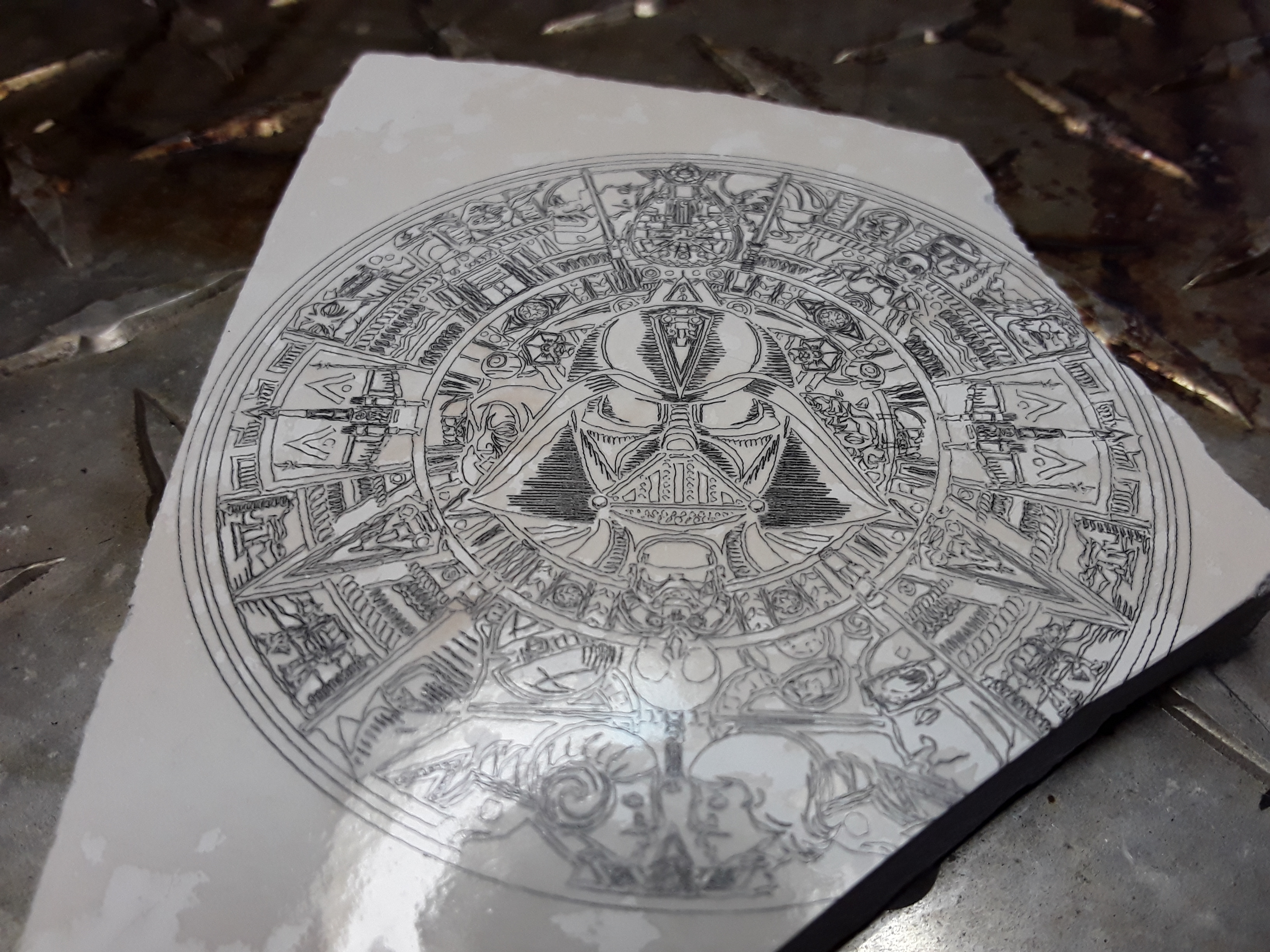
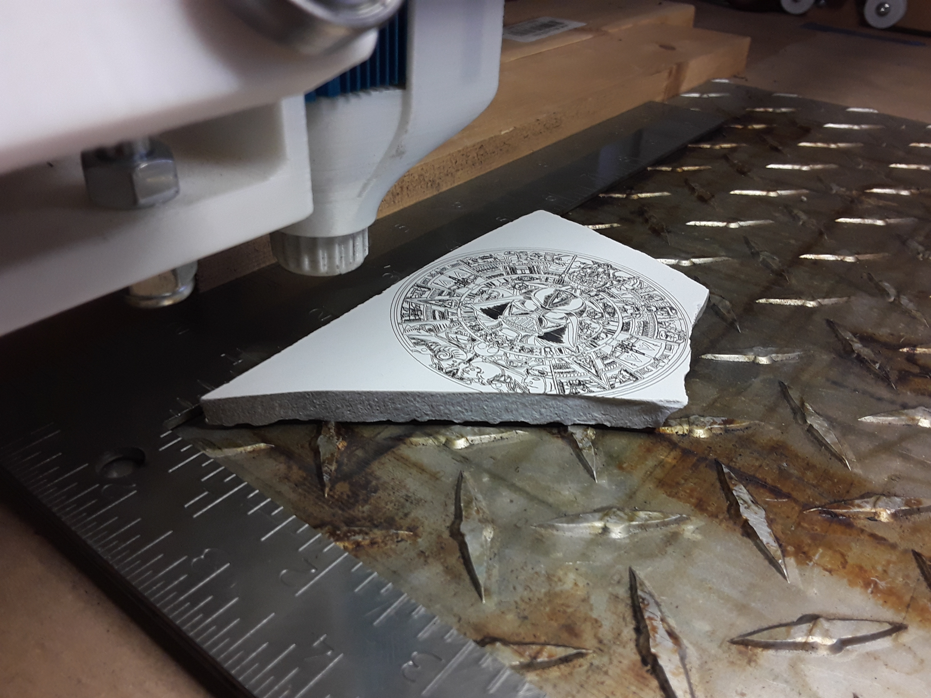
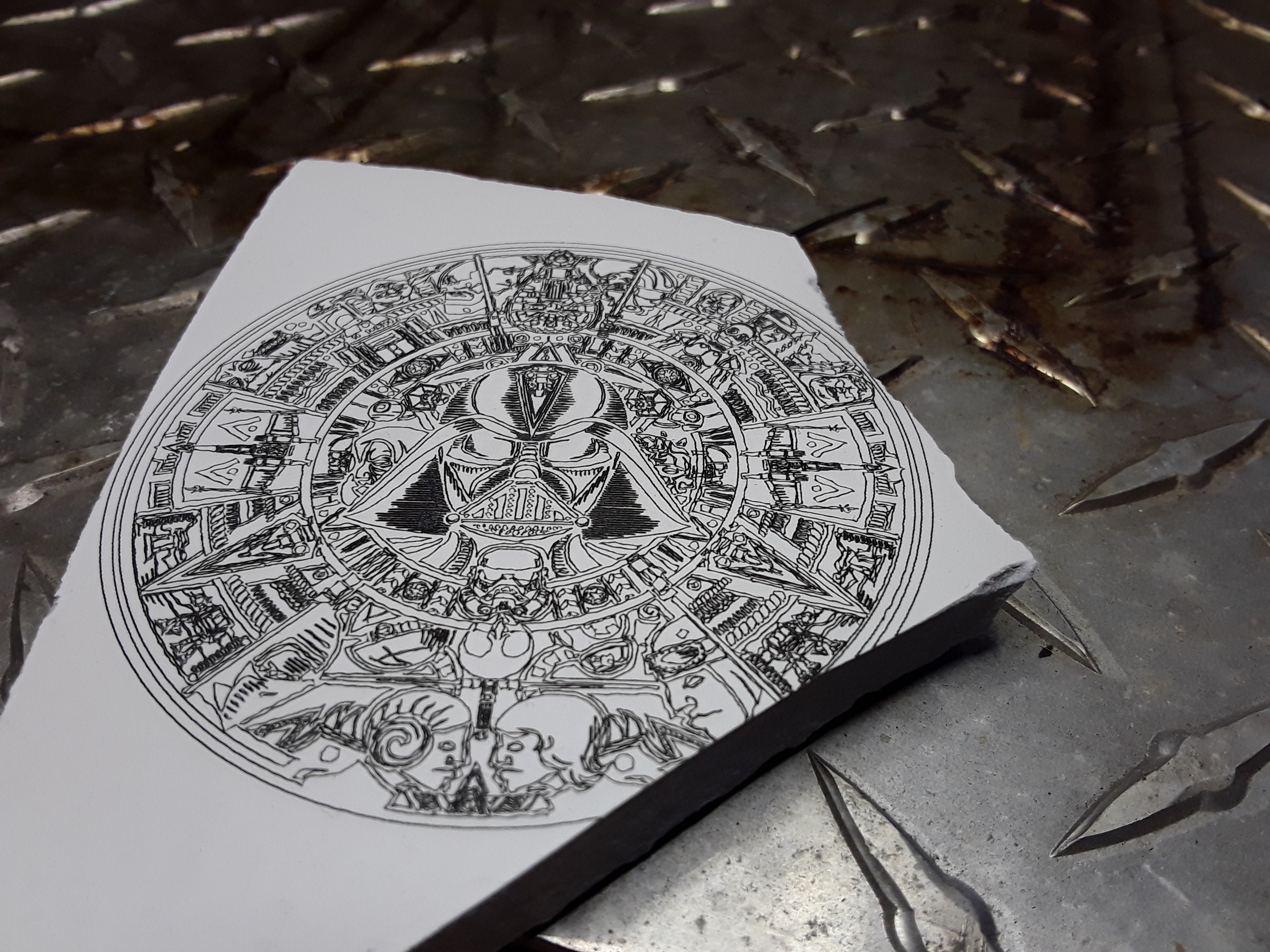
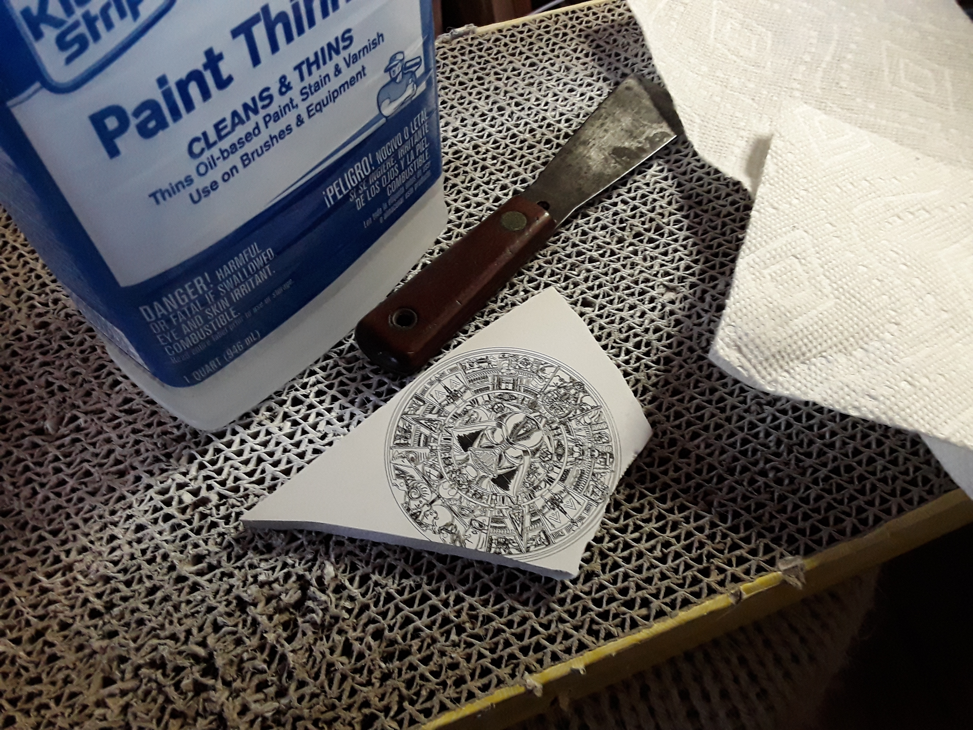
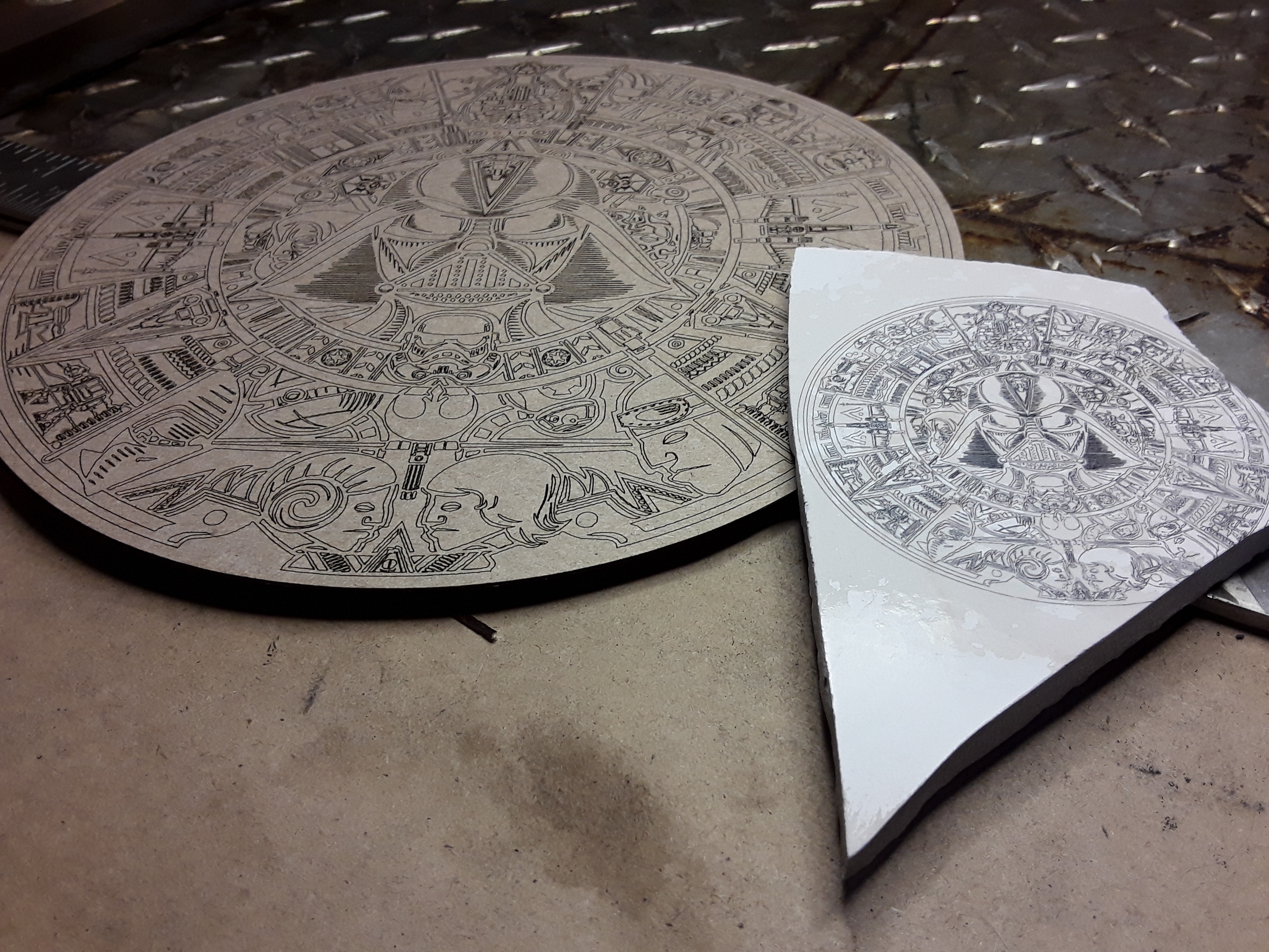
Unearthed in my yard – just today – a “genuine fake” piece of broken aztec pottery with “genuine fake” aztec calendar…

Vector engraved on ceramic tile (FoamRipper 2.5 watt laser, 1200 mm/min, 100% power, 70mm diameter)…

Flat-white painted surface just after engraving…
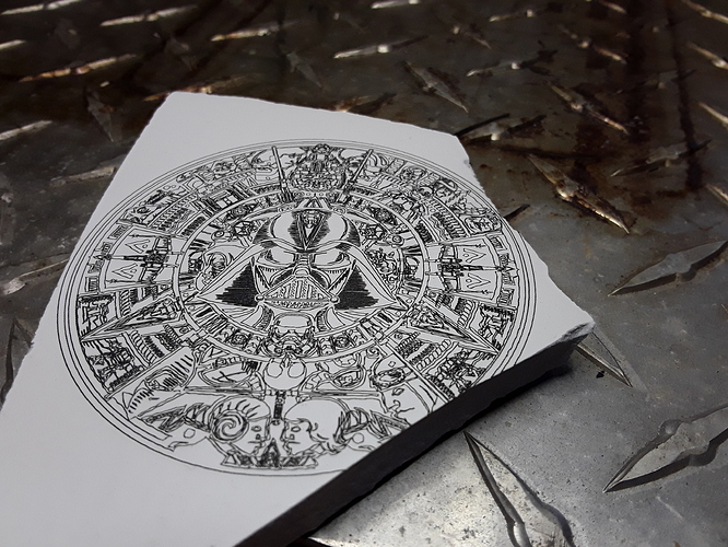
Tools of the trade (Thanks again, @Bulldog!)…

Poor paint removal job (need to get more thinner) and 200mm chipboard version…

– David
Unearthed in my yard – just today – a “genuine fake” piece of broken aztec pottery with “genuine fake” aztec calendar…
Vector engraved on ceramic tile (FoamRipper 2.5 watt laser, 1200 mm/min, 100% power, 70mm diameter)…
Flat-white painted surface just after engraving…
Tools of the trade (Thanks again, @Bulldog!)…
Poor paint removal job (need to get more thinner) and 200mm chipboard version…
– David
dkj4linux
Elite member
Another FoamRipper upgrade!?!
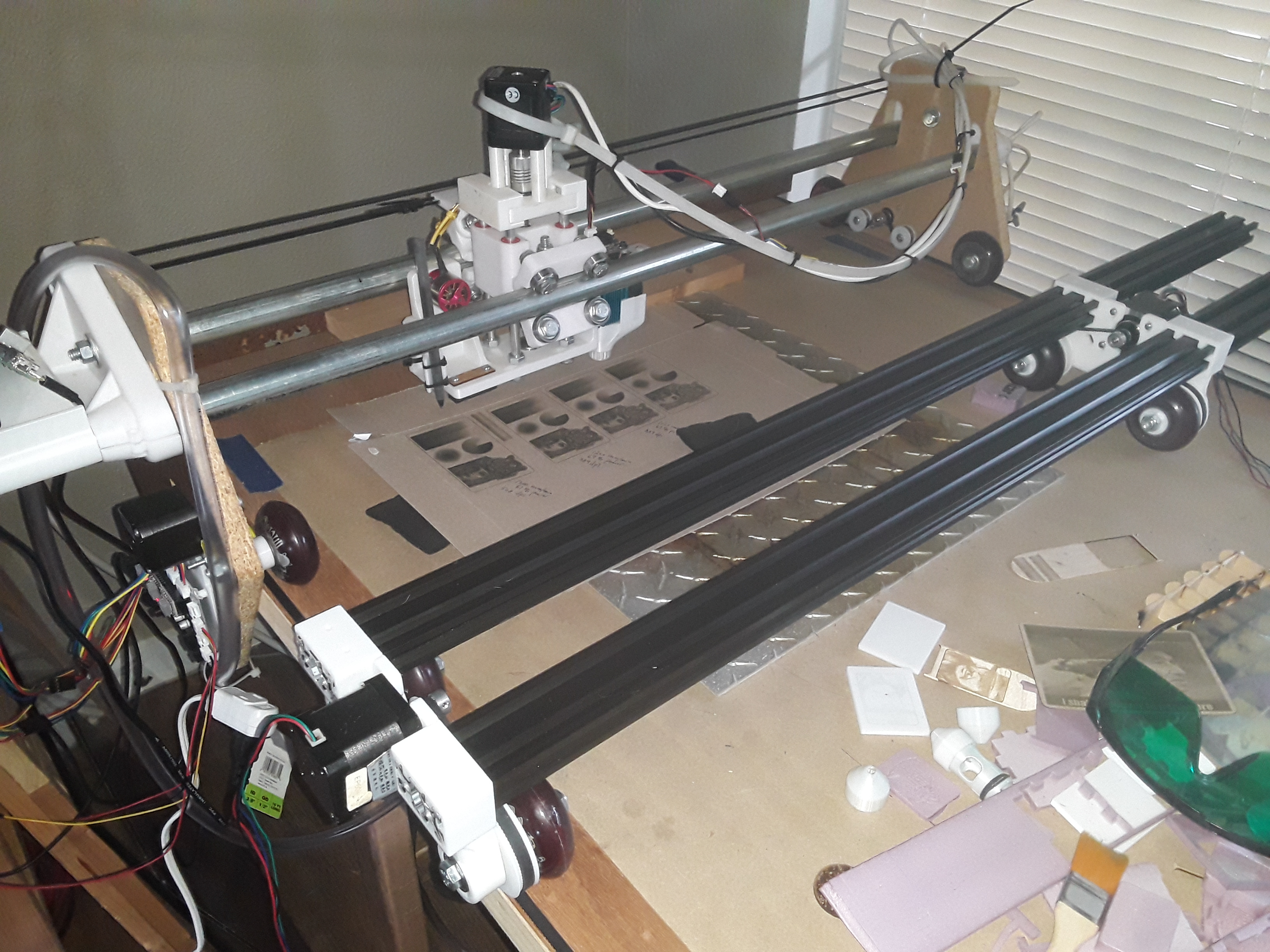
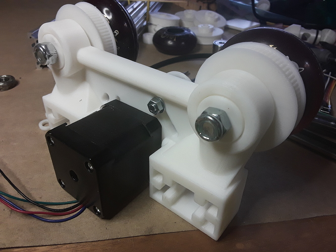
Recently inspired by @geodave’s “Rolling Plotter” build, I couldn’t shake the feeling that this could be a really neat gantry for FoamRipper. I modified Dave’s wheel design to use the 60mm skate wheels used on LowRider and FoamRipper… and look forward to duplicating his plotter design – at least mechanically – going forward.

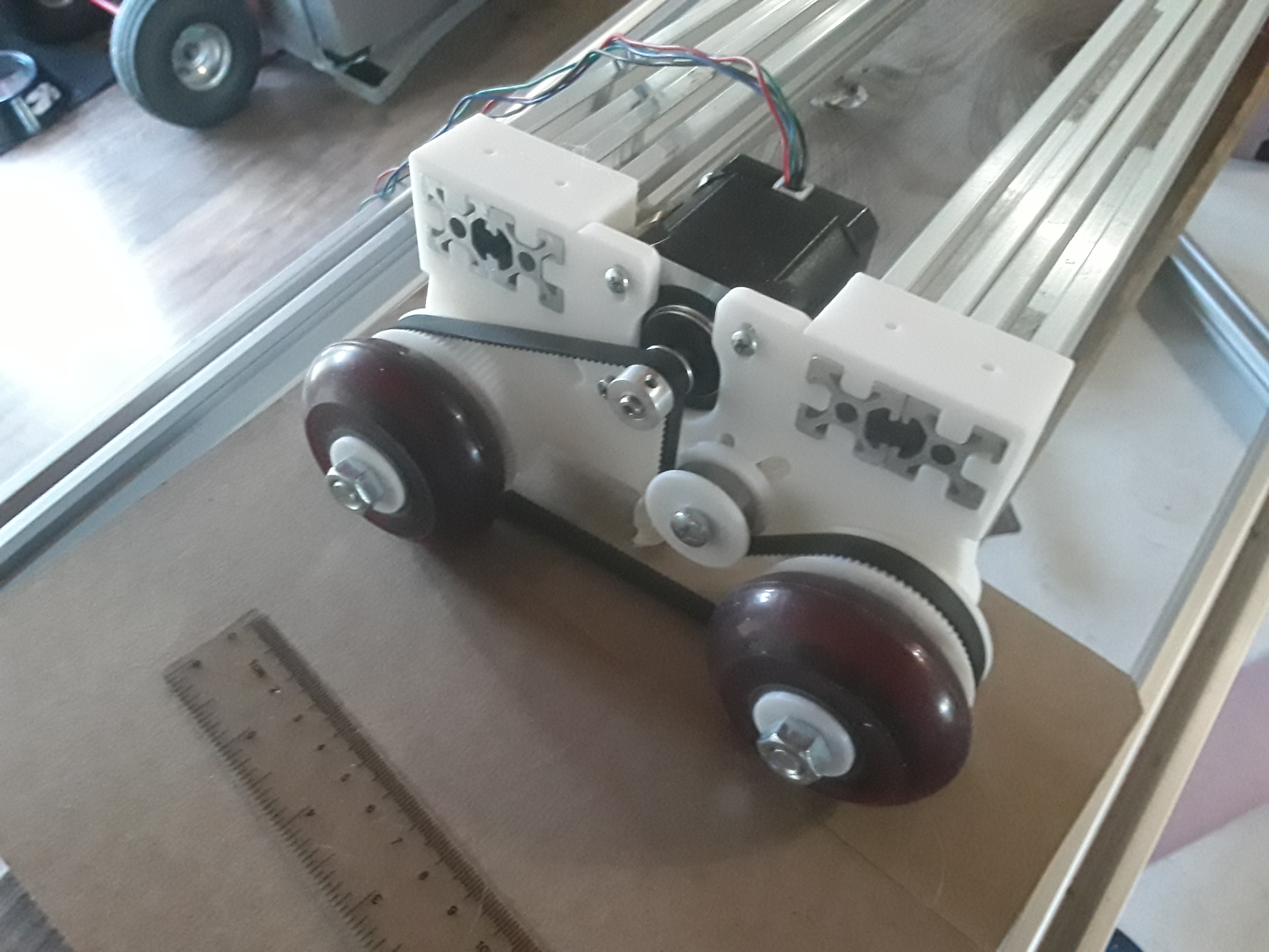
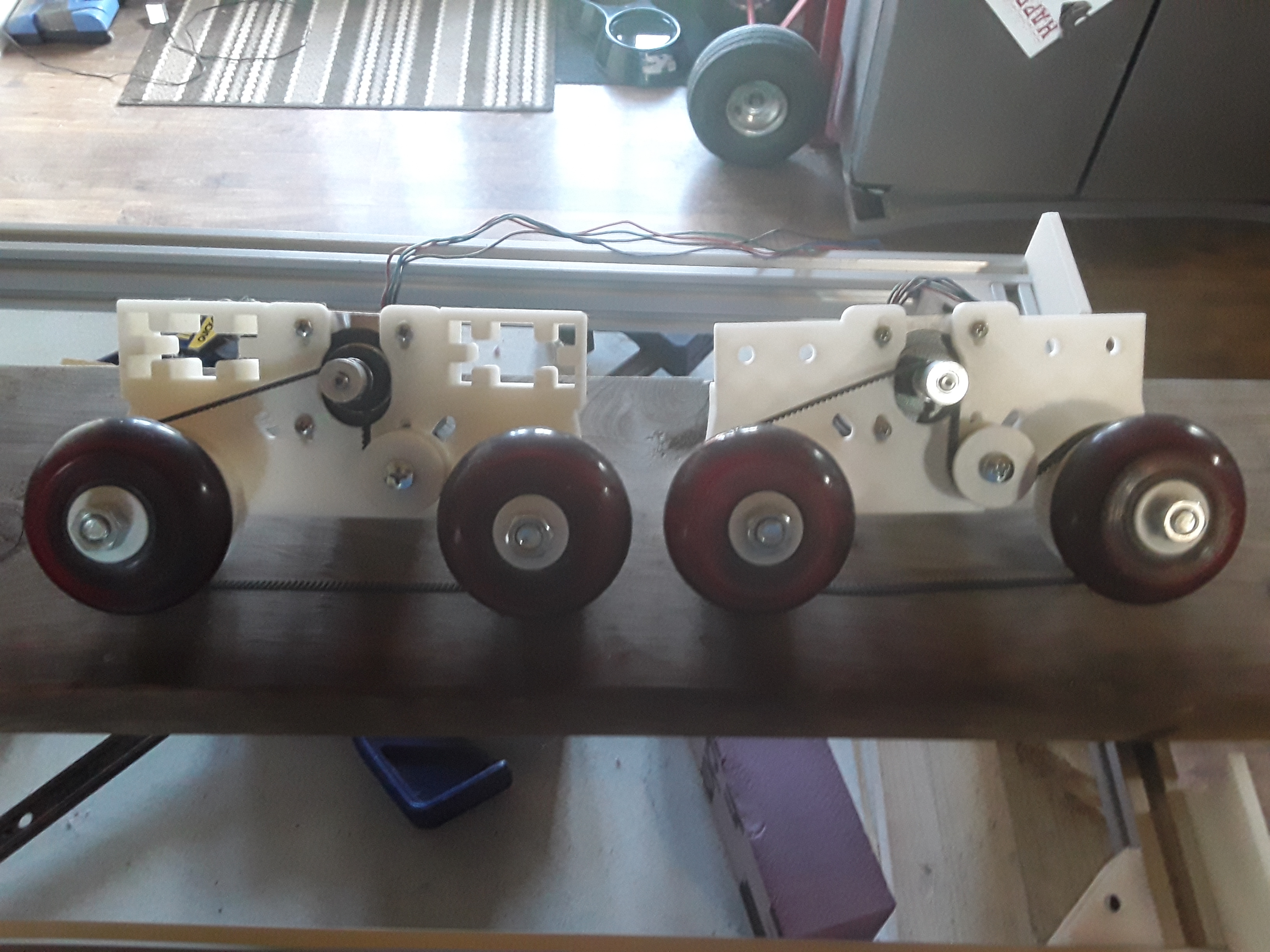
In this design the skate wheels, instead of free-wheeling, are driven. A printed 78(?) tooth wheel hub fits snugly where the inner bearing ordinarily goes and a simple filler hub replaces the outer bearing. A 444 mm closed-loop belt, an idler bearing, and a stepper motor and drive gear round out the drive mechanics mounted on the endplate…

I also modified the extrusion to endplate connection to allow adjustable spacing/span between the drive wheel assemblies. It also allows for reversible endplate installation… wheels inside or wheels outside.

Though the rails are shown flush in this photo, I suspect any excess rail could hang over at this end to allow a small shelf to be affixed for the electronics and display… similar to the existing gantry.

Next up, I’ll try to get the motors wired up and move this axis… which will be the X-axis. I then hope to be able to use Dave’s motor and idler mounts and moving carriage/plate for the Y axis. Finally I’ll take a look at his Z-axis… I can’t remember off-hand whether he wound up using a stepper or servo. Once all axes are moving properly, plotter functionality will be the first order of business… and the obligatory MPCNC crown. Then… probably laser.
Always fun, a new machine build. Later.
– David
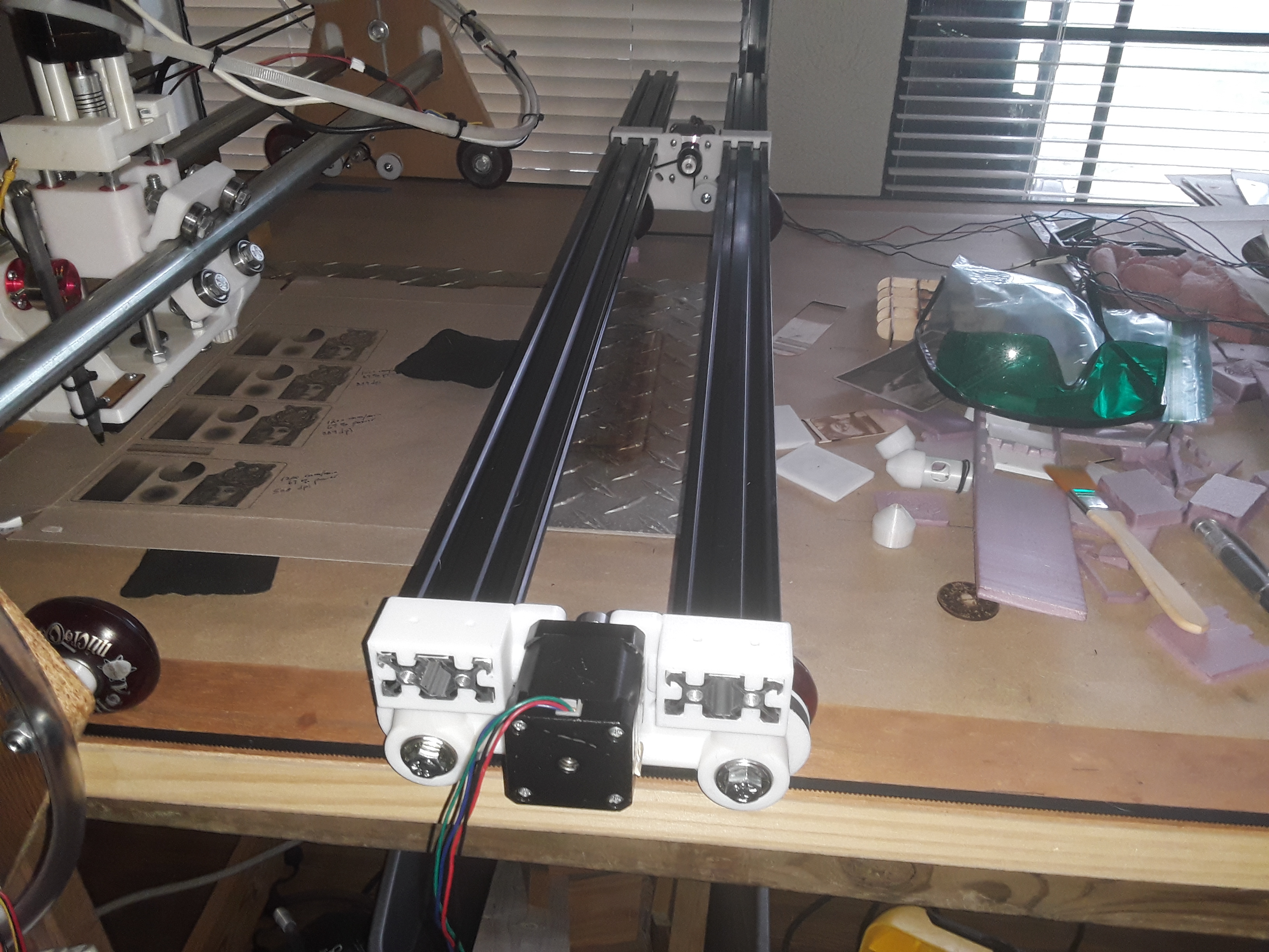
Recently inspired by @geodave’s “Rolling Plotter” build, I couldn’t shake the feeling that this could be a really neat gantry for FoamRipper. I modified Dave’s wheel design to use the 60mm skate wheels used on LowRider and FoamRipper… and look forward to duplicating his plotter design – at least mechanically – going forward.
In this design the skate wheels, instead of free-wheeling, are driven. A printed 78(?) tooth wheel hub fits snugly where the inner bearing ordinarily goes and a simple filler hub replaces the outer bearing. A 444 mm closed-loop belt, an idler bearing, and a stepper motor and drive gear round out the drive mechanics mounted on the endplate…
I also modified the extrusion to endplate connection to allow adjustable spacing/span between the drive wheel assemblies. It also allows for reversible endplate installation… wheels inside or wheels outside.
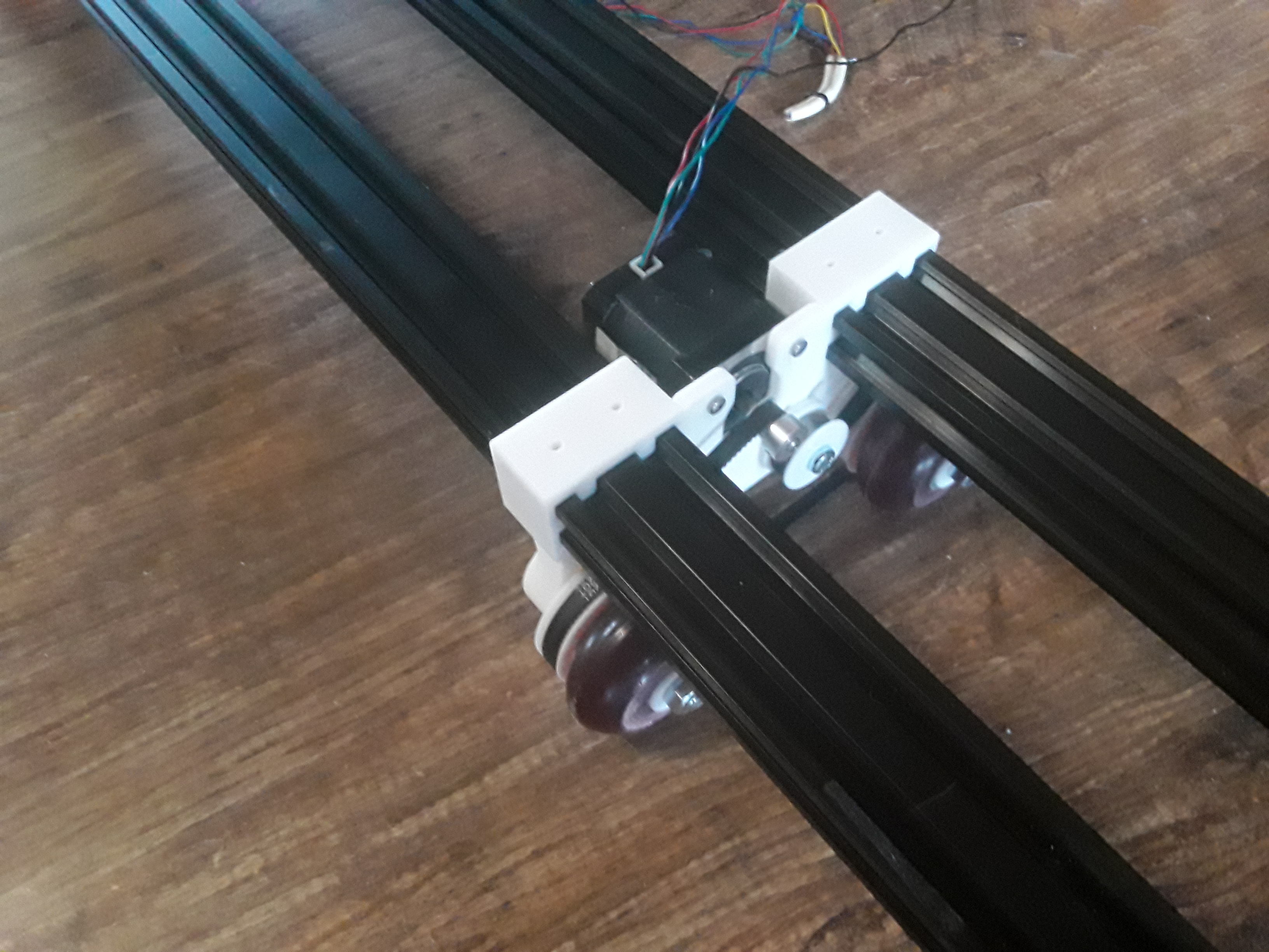
Though the rails are shown flush in this photo, I suspect any excess rail could hang over at this end to allow a small shelf to be affixed for the electronics and display… similar to the existing gantry.
Next up, I’ll try to get the motors wired up and move this axis… which will be the X-axis. I then hope to be able to use Dave’s motor and idler mounts and moving carriage/plate for the Y axis. Finally I’ll take a look at his Z-axis… I can’t remember off-hand whether he wound up using a stepper or servo. Once all axes are moving properly, plotter functionality will be the first order of business… and the obligatory MPCNC crown. Then… probably laser.
Always fun, a new machine build. Later.
– David
dkj4linux
Elite member
I also made a really neat "discovery" on this last round of Rolling Plotter endplate modifications.
I often have an existing STL and need to alter it in some way. For simple mods, TinkerCAD can be really handy. For others, not so.
My preferred CAD is Onshape. But importing an STL into Onshape gives a “mesh” that can be good for picking off reference points and measurements… but can’t be altered directly. I have found that STEP files are quite good however… when they exist. So, I googled “STL to STEP conversion” and found that FreeCAD can often pull this trick off successfully… as well as Fusion360 (but this isn’t a path I’m willing to take). Turns out, FreeCAD is now available as an AppImage… which for this Linux user means “download, make it executable, and launch it”. Even on Chromebook with Linux(beta) enabled… YAY!
Anyway, launch FreeCAD, open your STL, switch into “Part” mode, Part->“Create Shape from Mesh”, and then File->“Export” the resulting “shape” as STEP. If all goes well, you now have a “solid model” to import into Onshape.
I did this conversion successfully with Dave’s “End_plate-Rev6” STL and then altered it to accommodate the adjustable extrusion features of my final(?) endplate.
How neat is that??? – David
dkj4linux
Elite member
Belt stretch is never a concern for me as my machines rarely stay in the same configuration for very long... and I'm certainly never going to wear one out from "over-use"...Some interesting stuff going on there, David! The thought occurred to me that the wheeled drives with short tooth belts are probably more precise over time, versus typical CNC (and my machine) with long belts and their stretching over time. Your thoughts?
Concerning the closed-loop belts, I had started playing with @geodave's Rolling Plotter some months ago. Got to the point of ordering some 444 mm closed-loop belts and then pushed everything into a corner while waiting on their delivery. On a much slower boat than normal… my 444mm belts were finally deemed “LOST [at sea]” by the shipper. With the pandemic and shipping disruptions, I decided against reordering anything right now and had pretty much given up on having a rolling plotter in my future anytime soon. Then a few days ago, mysteriously, a small package arrived in the mailbox… looking fine and normal, just LATE! Getting pretty bored just playing around with my laser, I was starting to look for something new to play with... and then this arrived, just in time!
So I started playing with Dave's original endplates, which I had already printed… and started modding them to take advantage of parts in my stash. With zillions of 608 bearings on hand, I elongated one idler bearing slot to allow a single 608 idler to replace the two-bearing idler setup of the original endplate.
With the belt routing looking reasonable for now, I then took a look at the extrusion to endplate connection. I have a couple of 1000mm 2040 extrusions that I’m reluctant to cut to length until I know more about how I might use this thing… and decided I’d really like to try setting it to the same width as my FoamRipper gantry and work surface. So I reworked the extrusion “shelf” to allow the extrusions to “pass through”, for width adjustment and even endplate reversal (wheels inside or outside) if necessary.
The endplate extrusion mods and the near-original (the idler slot had already been elongated) for fixed-length extrusions...
Having now printed a second endplate to match, I'm to the point of getting this thing wired up and moving. I’m hoping to honor Dave’s mechanical design for the remainder of this build as much as possible… until I know more about how I might use it.
– David
dkj4linux
Elite member
Some progress…
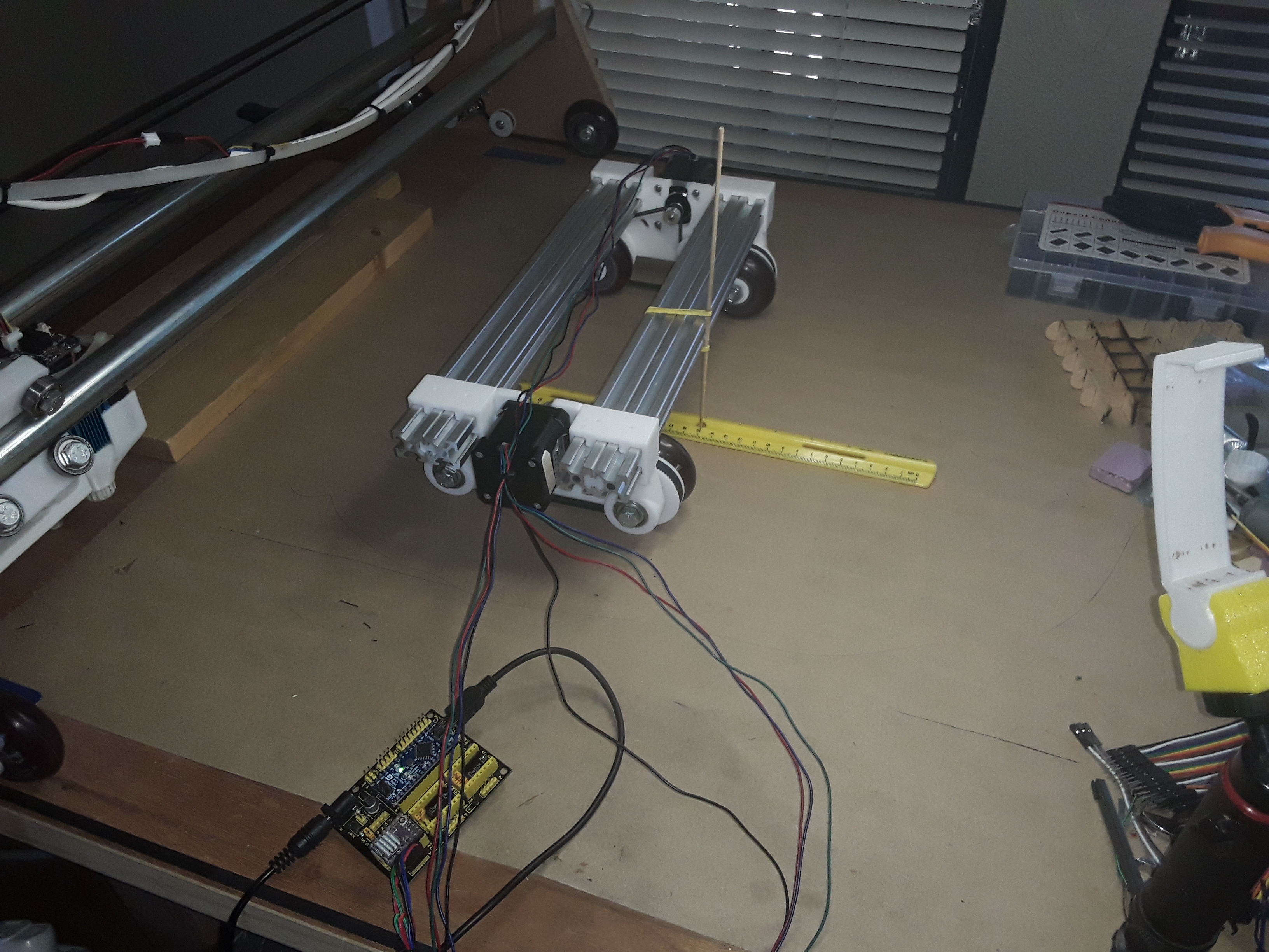
Wired up the plotter/gantry and got things moving in the proper direction. Did a quick, rough, steps/mm calibration and the to & fro motion here ranges over +/-150 millimeters, total 300 millimeters.
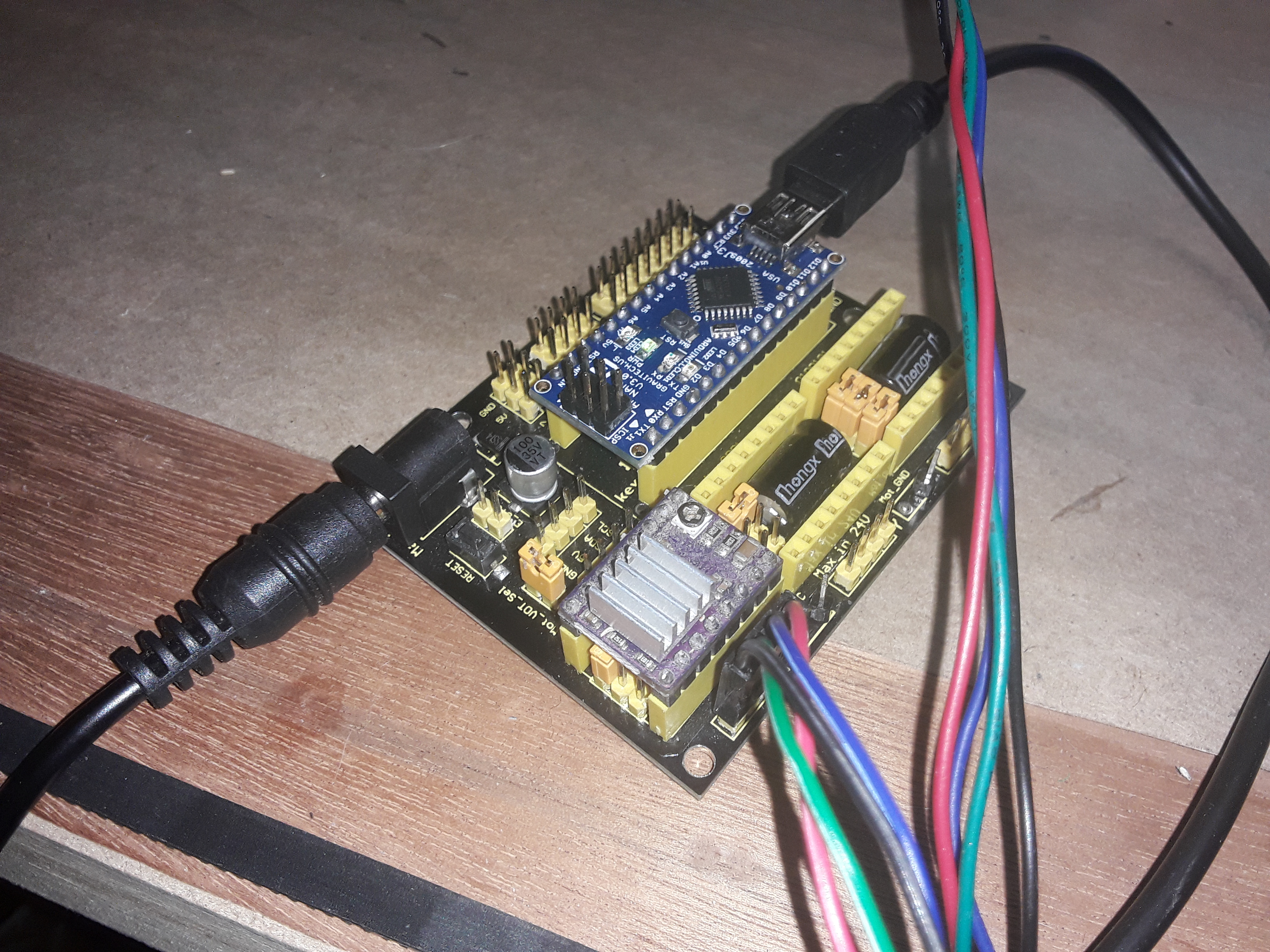
Picked one of my little Nano-based Grbl controllers from my stash and verified its running Grbl v1.1h. I have the motors wired in series, ala MPCNC… running on one DRV8825.

Slid the trucks/tractors on to shorter lengths of extrusion for test purposes…

There is a slight drift away from the camera in the video. I’m believing wheel friction on one side may be greater than the other… I just tightened until there was no wheel play that I could tell. I’m sure that a side-board or guide of some kind will be necessary to do accurate work.
It’s a start…
– David
Wired up the plotter/gantry and got things moving in the proper direction. Did a quick, rough, steps/mm calibration and the to & fro motion here ranges over +/-150 millimeters, total 300 millimeters.
Picked one of my little Nano-based Grbl controllers from my stash and verified its running Grbl v1.1h. I have the motors wired in series, ala MPCNC… running on one DRV8825.
Slid the trucks/tractors on to shorter lengths of extrusion for test purposes…
There is a slight drift away from the camera in the video. I’m believing wheel friction on one side may be greater than the other… I just tightened until there was no wheel play that I could tell. I’m sure that a side-board or guide of some kind will be necessary to do accurate work.
It’s a start…
– David
Springer
Member
So, if I understand correctly, you took the bearings out of the wheels and put them in the end plates? Interesting, I wonder if that is more stable than rigid axles/bearings in wheels? Considering the cantilever of the axles from bearings I would think not. Of course the loads are so low it may make no difference. No doubt spacing between bearings would be important - wider to increase rigidity.
dkj4linux
Elite member
Actually I just modded the endplate @geodave had designed... but am unsure why he had bearings there, as he already had them in his printed wheels as well. His would have worked fine with just a rigid axle affixed to the endplate. My problem is that I needed/WANTED to drive a skate wheel that I already had on hand (and is used on LR/FR), that normally free-wheels... so needed to firmly affix a large gear/sprocket to it in some way. Simplest was just to create the hub halves to go where the bearings normally do. I know this isn't best but was trying to use common parts I already had and still stay relatively close to @geodave's design... and trust the relatively light loads to bail me out. If necessary, I'm sure I can redesign/rearrange my wheel hub/sprocket set up to include the bearings that were replaced... but for now, and until I know better, KISS is king.
dkj4linux
Elite member
Okay, okay... you've shamed me back onto the righteous path. Satisfied?
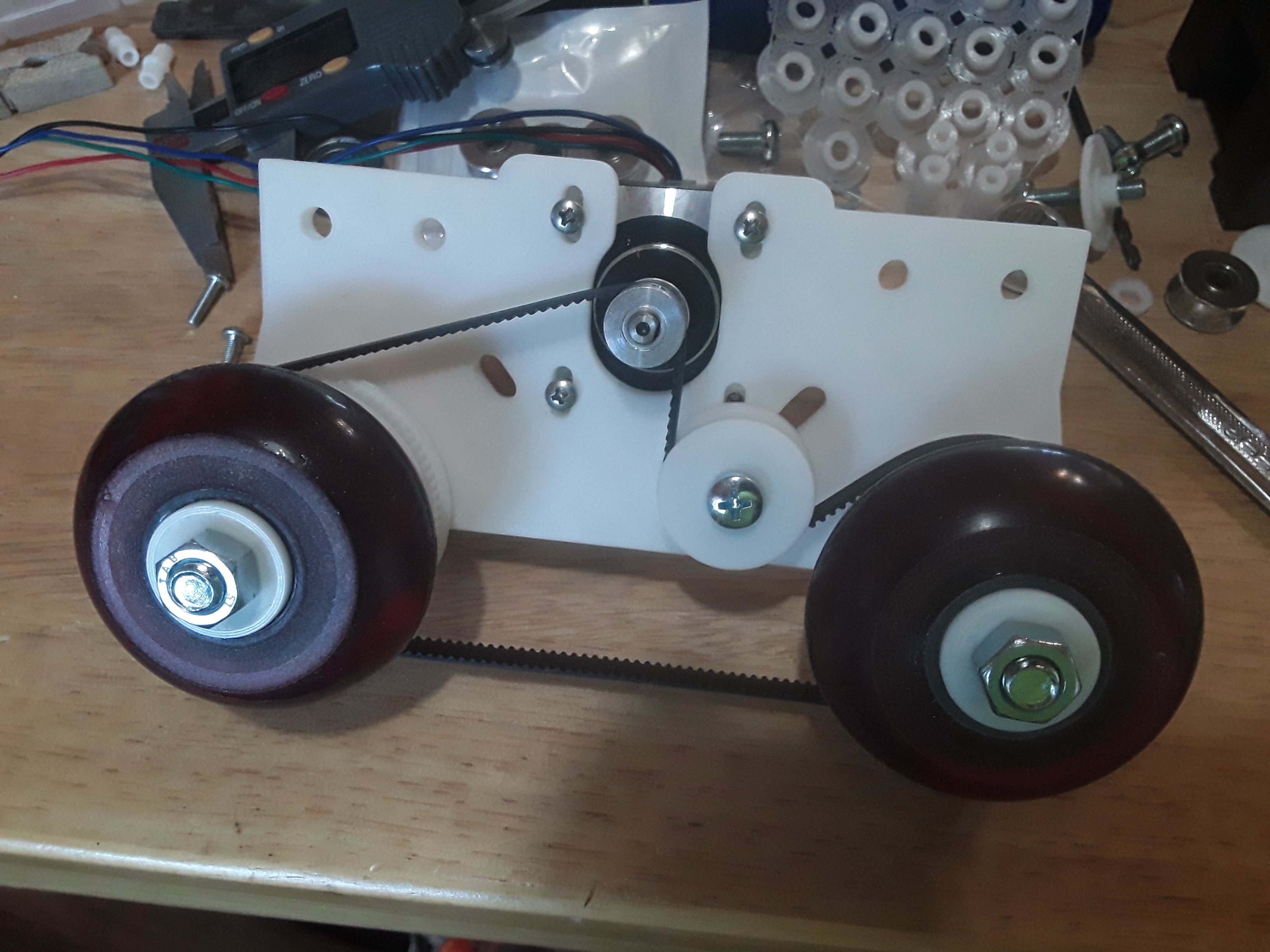
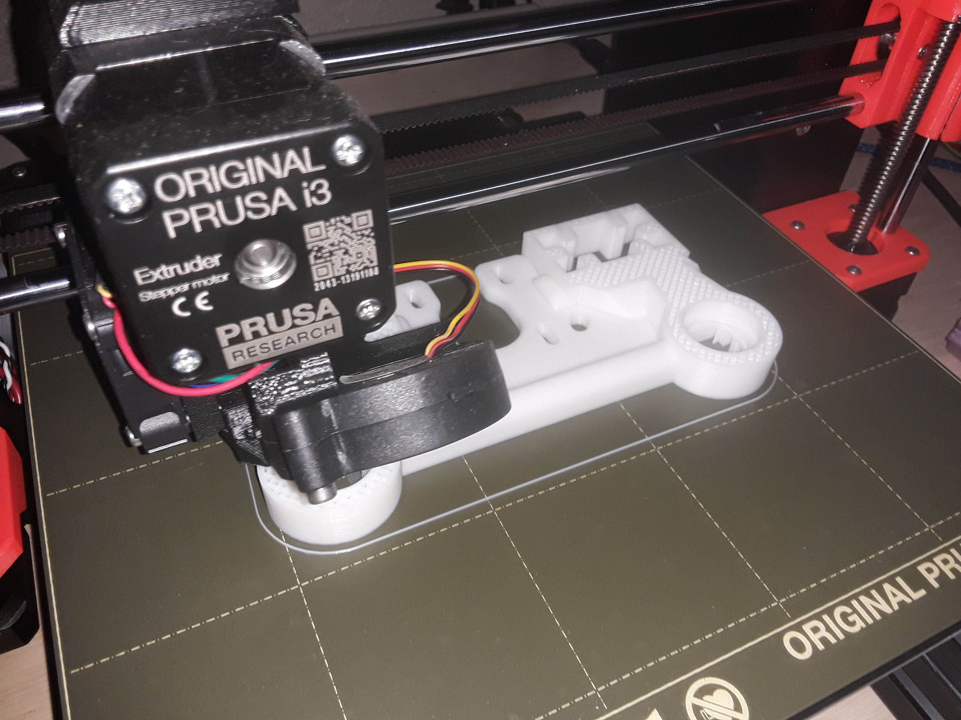
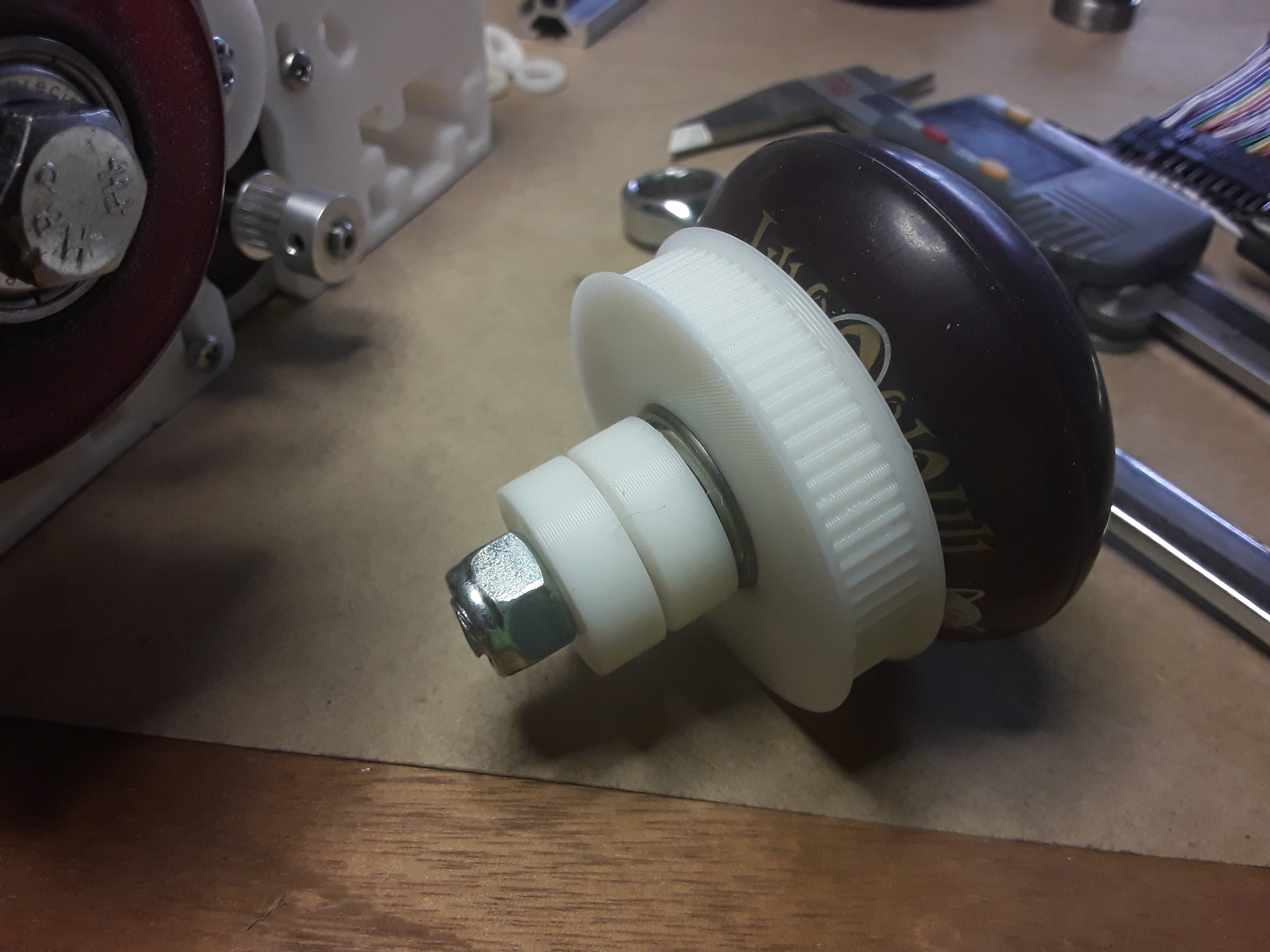
I started looking at my printed sprocket part and decided a 608 bearing could easily be housed in the sprocket section and the outer filler hub replaced with the original bearing. So now both bearings are back in place in the wheel and the endplate can be modded to provide a rigid axle attachment.

.jpg")

There is a ripple effect, of course. A couple of parts will need to be modded and re-printed... and a number of new spacers will be required. But, hey! Nobody ever said it'd be easy to stay on the "straight and narrow"...
-- David
I started looking at my printed sprocket part and decided a 608 bearing could easily be housed in the sprocket section and the outer filler hub replaced with the original bearing. So now both bearings are back in place in the wheel and the endplate can be modded to provide a rigid axle attachment.
There is a ripple effect, of course. A couple of parts will need to be modded and re-printed... and a number of new spacers will be required. But, hey! Nobody ever said it'd be easy to stay on the "straight and narrow"...
-- David
dkj4linux
Elite member
No, you were right to question it... and I knew better. I just needed to study it a little longer and not be in such a rush to get something printed and moving. Thank you!
Regards the use of 5/16" bolts in 8mm holes and as axles in bearing bores, I usually just try to insure the bearings sit on the full-diameter bolt shank. Most often, turning it end-for-end, one way or the other, allows that to happen. That... or just use way-overlong bolts and print SPACERS to allow it to all tighten up!
Regards the use of 5/16" bolts in 8mm holes and as axles in bearing bores, I usually just try to insure the bearings sit on the full-diameter bolt shank. Most often, turning it end-for-end, one way or the other, allows that to happen. That... or just use way-overlong bolts and print SPACERS to allow it to all tighten up!
dkj4linux
Elite member
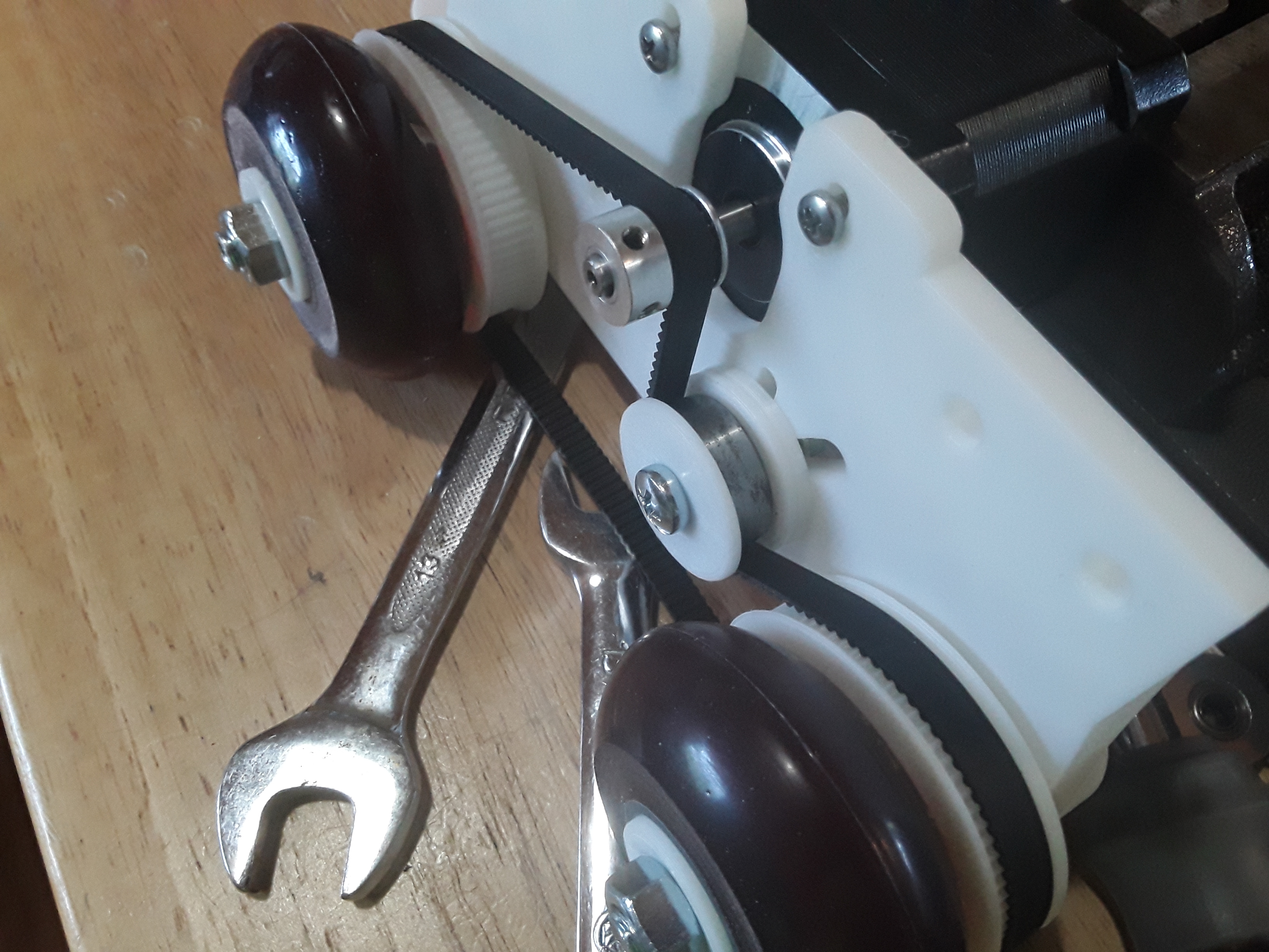
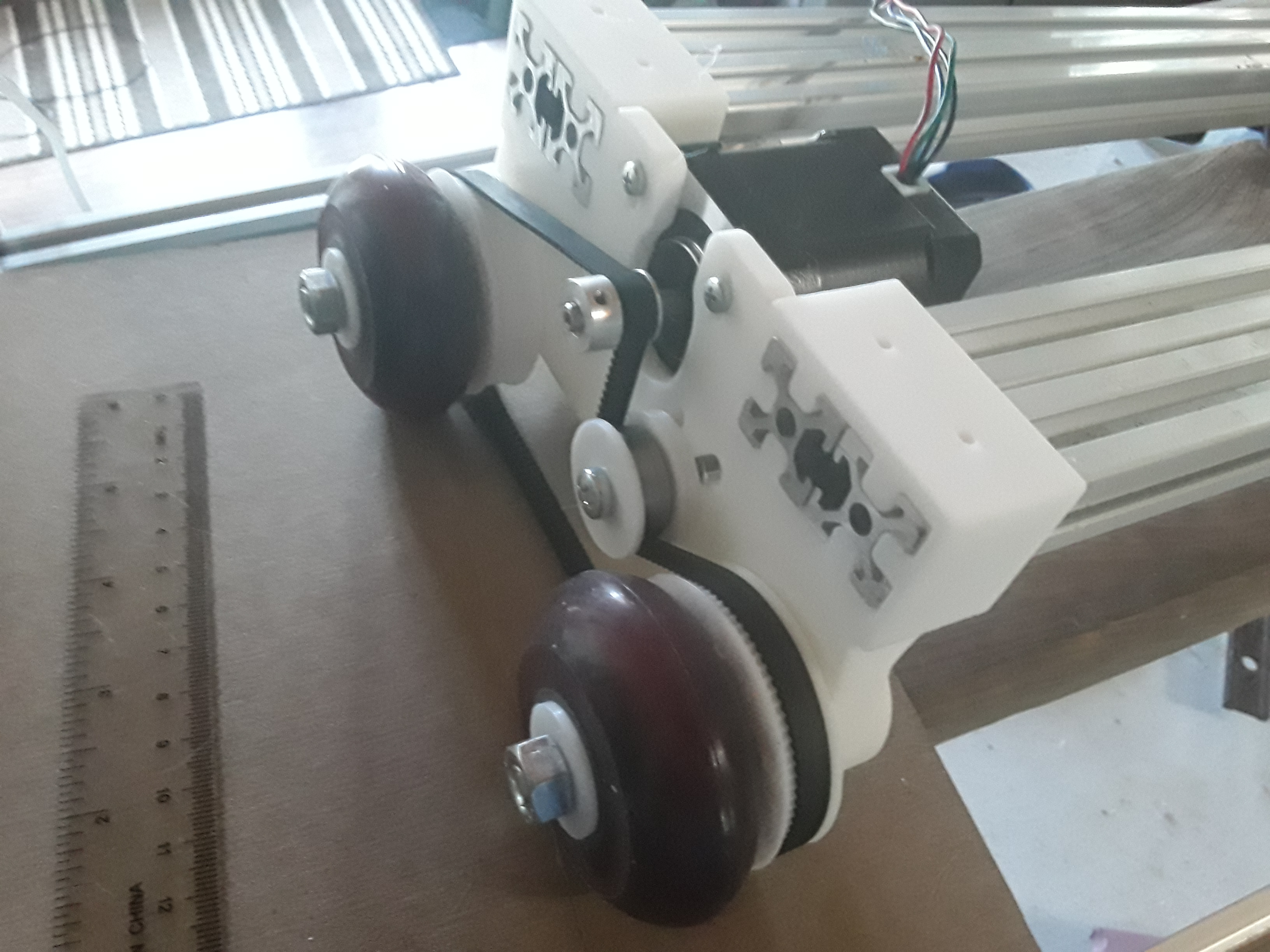
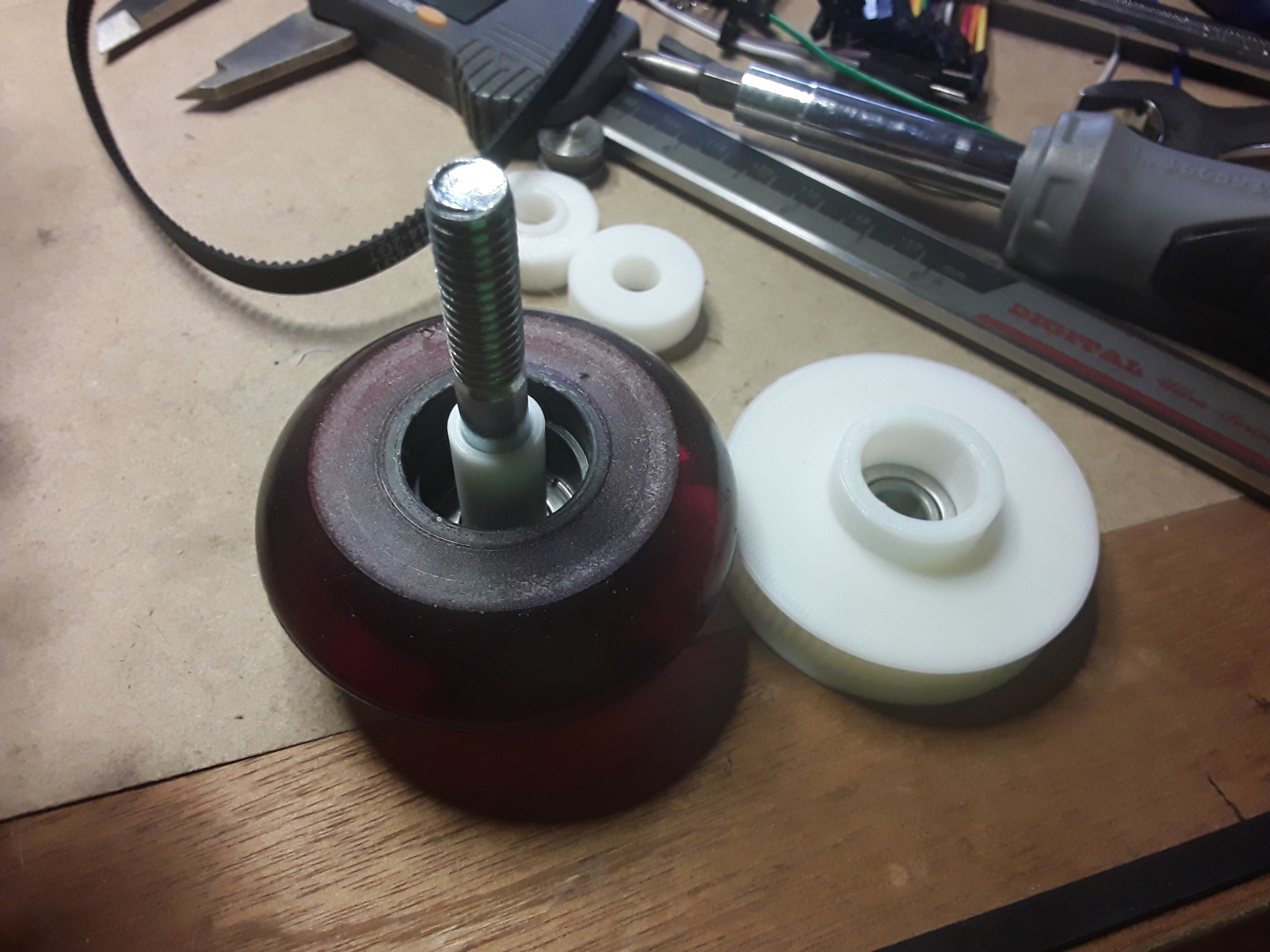
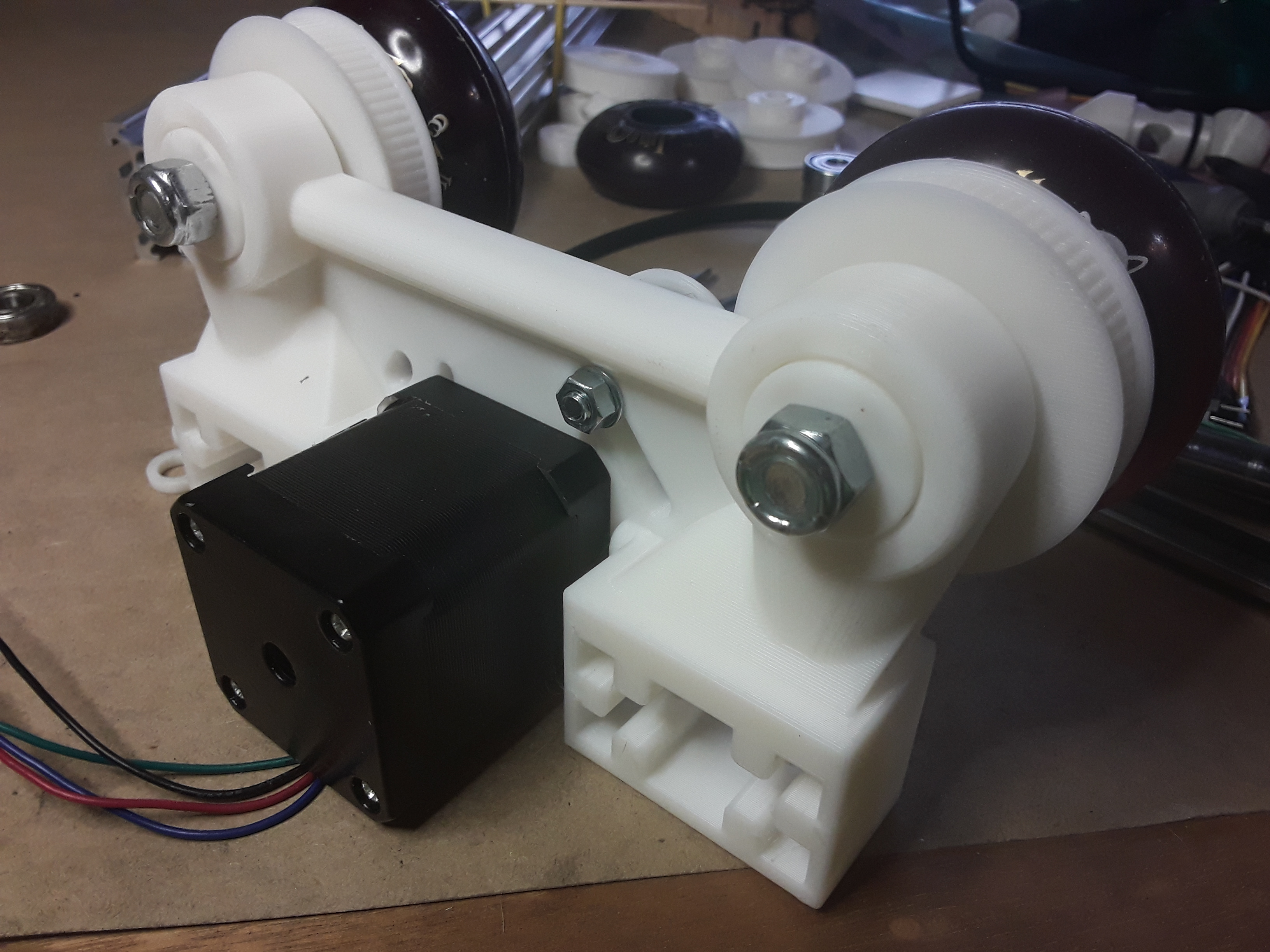
Short of modifying and re-printing my endplates yet -- may have a couple more mods to make -- I’ve patched together a wheel/bearing setup that seems workable for now.
I’ve got the wheel bearings back in place (where they belong), with a new bearing spacer…

and made “plugs” to fill the space where the bearings once sat in the endplate…

and, finally, assembled…
I’m wondering now if I might be able to use Openbuild’s mini-V linear actuator “verbatim”… by allowing the 2040 rail/axis to extend sufficiently to allow the motor and idler mounts/housings to sit outside the wheels/workarea. I’d also have to remove the front “notch” where the extrusion passes-through the endplate to provide clearance for the belt to pass through.
I think I’ll go ahead and print a set of those linear actuator parts… as this seem like it could be handy at some point down the road, regardless. I’ve already got @geodave's motor/idler supports and carriage printed and can use those if the linear actuator idea doesn’t pan out.
– David
I’ve got the wheel bearings back in place (where they belong), with a new bearing spacer…
and made “plugs” to fill the space where the bearings once sat in the endplate…
and, finally, assembled…
I’m wondering now if I might be able to use Openbuild’s mini-V linear actuator “verbatim”… by allowing the 2040 rail/axis to extend sufficiently to allow the motor and idler mounts/housings to sit outside the wheels/workarea. I’d also have to remove the front “notch” where the extrusion passes-through the endplate to provide clearance for the belt to pass through.
I think I’ll go ahead and print a set of those linear actuator parts… as this seem like it could be handy at some point down the road, regardless. I’ve already got @geodave's motor/idler supports and carriage printed and can use those if the linear actuator idea doesn’t pan out.
– David
Springer
Member
It was just a question, of course, but I guess it got your juices flowing! I hadn't thought about the smaller OD in the threaded portion.
Similar threads
- Replies
- 6
- Views
- 1K
- Replies
- 8
- Views
- 1K
- Replies
- 6
- Views
- 720
- Replies
- 0
- Views
- 298