"Design and manufacture
Overview

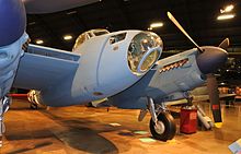
B Mk IV nose closeup showing bombsight and clear nose, plus engine nacelles and undercarriage.
While timber construction was considered outmoded by some, de Havilland claimed that their successes with techniques used for the DH 91 Albatross could lead to a fast light bomber using monocoque sandwich shell construction.
[66] Arguments in favor of this included speed of prototyping, rapid development, minimisation of jig building time, and employment of a separate category of workforce. At the same time, they had to fight conservative Air Ministry views on defensive armament. Guns and gun turrets would spoil the streamlining, losing speed and manoeuvrability. The ply-balsa-ply monocoque fuselage and one-piece wings with doped fabric covering gave smooth aerodynamic performance and low weight, combined with strength and stiffness. Whilst submitting these arguments, Geoffrey de Havilland funded his private venture until the eleventh hour. It was a success beyond all expectations. The initial bomber and photo reconnaissance versions were extremely fast, whilst the armament of subsequent variants might be regarded as primarily offensive.
The most-produced variant,
designated the FB Mk VI (Fighter-bomber Mark 6), was powered by two Merlin Mk 23 or Mk 25 engines driving three-bladed de Havilland hydromatic propellers. The typical fixed armament for an FB Mk VI was four Browning .303 machine guns and four 20 mm Hispano cannon while the offensive load consisted of up to 2,000 pounds (910 kg) of bombs, or eight RP-3 unguided rockets.
[67]
Performance
The design was noted for light and effective control surfaces that provided good manoeuvrability but required that the rudder not be used aggressively at high speeds. Poor aileron control at low speeds when landing and taking off was also a problem for inexperienced crews.
[68] For flying at low speeds, the flaps had to be set at 15°, speed reduced to 200 mph (320 km/h) and
rpm set to 2,650. The speed could be reduced to an acceptable 150 mph (240 km/h) for low speed flying.
[69] For cruising, the maximum speed for obtaining maximum range was 200 mph (320 km/h) at 17,000 lb (7,700 kg) weight.
[69]
The Mosquito had a low stalling speed of 120 mph (190 km/h) with undercarriage and flaps raised. When both were lowered, the stalling speed decreased from 120 to 100 mph (190 to 160 km/h). Stall speed at normal approach angle and conditions was 100 to 110 mph (160 to 180 km/h). Warning of the stall was given by buffeting and would occur 12 mph (19 km/h) before stall was reached. The conditions and impact of the stall were not severe. The wing did not drop unless the control column was pulled back. The nose drooped gently and recovery was easy.
[69]
Early on in the Mosquito's operational life, the intake shrouds that were to cool the exhausts on production aircraft overheated. Flame dampers prevented exhaust glow on night operations, but they had an effect on performance. Multiple ejector and open-ended exhaust stubs helped solve the problem and were used in the PR.VIII, B.IX and B.XVI variants. This increased speed performance in the B.IX alone by 10 to 13 mph (16 to 21 km/h).
[9]
Fuselage
The oval-section fuselage was a frameless
monocoque shell built in two vertically-separate halves formed over a
mahogany or
concrete mould.
[nb 13] Pressure was applied with
band clamps. The shell sandwich skins comprised birch three-ply outers, with cores of Ecuadorean
balsa.
[nb 14] In many generally smaller but vital areas, such as around apertures and attachment zones, stronger timbers, including aircraft-quality spruce, replaced the balsa core. The main areas of the sandwich skin were only 0.55 inches (14 mm) thick.
[70] Together with various forms of wood reinforcement, often of laminated construction, the sandwich skin gave great stiffness and torsional resistance. The separate fuselage halves speeded construction, permitting access by personnel working in parallel with others, as the work progressed.
[71]
Work on the separate half-fuselages included installation of control mechanisms and cabling. Screwed inserts into the inner skins that would be under stress in service were reinforced using round shear plates made from a fabric-Bakelite composite.
[72]
Transverse bulkheads were also compositely built-up with several species of timber, plywood and balsa. Seven vertically-halved bulkheads were installed within each moulded fuselage shell before the main "boxing up" operation. Bulkhead number seven was especially strongly built, since it carried the fitments and transmitted the aerodynamic loadings for the tailplane and rudder.
[73][nb 15] The fuselage had a large ventral section cut-out, strongly reinforced, that allowed the fuselage to be lowered onto the wing centre-section at a later stage of assembly.
[75]
For early production aircraft, the structural assembly adhesive was
Casein-based. At a later stage, this was replaced by "
Aerolite", a synthetic
urea-formaldehyde type, which was more durable.
[76][nb 16] To provide for the edge joints for the fuselage halves, zones near the outer edges of the shells had their balsa sandwich cores replaced by much stronger inner laminations of birch plywood. For the bonding together of the two halves ("boxing up"), a longitudinal cut was machined into these edges. The profile of this cut was a form of V-groove. Part of the edge bonding process also included adding further longitudinal plywood lap-strips on the outside of the shells.
[71][75] The half-bulkheads of each shell were bonded to their corresponding pair in a similar way. Two laminated wooden clamps were used in the after portion of the fuselage to provide supports during this complex gluing work. The resulting large structural components had to be kept completely still and held in the correct environment until the glue cured.
[71][79]
For finishing, a covering of
doped Madapolam (a fine plain woven cotton) fabric was stretched tightly over the shell and several coats of red, followed by silver dope were added, followed by the final camouflage paint.
[80]
Wing

A preserved Mosquito at the U.S. Air Force Museum (former TT Mk 35 which was restored to B Mk XVI configuration).
[81] Note the air and oil coolant radiators in the leading edge of the wing, intake for the two-stage Merlin's intercooler radiator behind the propeller blade, and the carburettor intake with ice guard behind and below.
American F-8 Mosquito nose;
USAAF markings,
PRU Blue finish at the
National Museum of the United States Air Force.
The all-wood wing pairs comprised a single structural unit throughout the wingspan, with no central longitudinal joint.
[82] Instead, the spars ran from wingtip to wingtip. There was a single continuous main spar and another continuous rear spar. Because of the combination of dihedral with the forward sweep of the trailing edges of the wings, this rear spar was one of the most complex units to laminate and to finish machining after the bonding and curing. It had to produce the correct 3D tilt in each of two planes. Also it was designed and made to taper from the wing roots towards the wingtips. Both principal spars were of ply box construction, using in general 0.25 in. plywood webs with laminated spruce flanges, plus a number of additional reinforcements and special details.
Spruce and plywood ribs were connected with gusset joints. Some heavy-duty ribs contained pieces of ash and walnut as well as the special five ply that included veneers laid up at 45 degrees. The upper skin construction was in two layers of 0.25 in. five ply birch, separated by Douglas fir stringers running in the span-wise direction.
[83]
The wings were covered with Madapolam fabric and doped in a similar manner to the fuselage. The wing was installed into the roots by means of four large attachment points.
[84][85] The engine radiators were fitted in the inner wing, just outboard of the fuselage on either side. These gave less drag. The radiators themselves were split into three sections: an oil cooler section outboard, the middle section forming the coolant radiator and the inboard section serving the cabin heater.
[86]
The wing contained metal framed and skinned
ailerons, but the flaps were made of wood and were hydraulically controlled. The nacelles were mostly wood, although, for strength, the engine mounts were all metal as were the undercarriage parts.
[87] Engine mounts of welded steel tube were added, along with simple landing gear oleos filled with rubber blocks. Wood was used to carry only in-plane loads, with metal fittings used for all triaxially loaded components such as landing gear, engine mounts, control surface mounting brackets, and the wing-to-fuselage junction.
[88] The outer leading wing edge had to be brought 22 inches (56 cm) further forward to accommodate this design.
[86] The main tail unit was all wood built. The control surfaces, the
rudder and
elevator, were
aluminium framed and fabric covered.
[87] The total weight of metal castings and forgings used in the aircraft was only 280 lb (130 kg).
[89]
In November 1944, several crashes occurred in the
Far East. At first, it was thought these were as a result of wing structure failures. The casein glue, it was said, cracked when exposed to extreme heat and/or monsoon conditions. This caused the upper surfaces to "lift" from the main spar. An investigating team led by Major
Hereward de Havilland travelled to India and produced a report in early December 1944 stating that "the accidents were not caused by the deterioration of the glue but by shrinkage of the airframe during the wet monsoon season".
[nb 17] However, a later inquiry by Cabot & Myers definitely attributed the accidents to faulty manufacture and this was confirmed by a further investigation team by the Ministry of Aircraft Production at
Defford, which found faults in six Mosquito marks (all built at de Havilland's Hatfield and Leavesden plants). The defects were similar, and none of the aircraft had been exposed to monsoon conditions or termite attack.
The investigators concluded that there were construction defects at the two plants. They found that the "...standard of glueing...left much to be desired.”
[91][92] Records at the time showed that accidents caused by "loss of control" were three times more frequent on Mosquitos than on any other type of aircraft. The Air Ministry forestalled any loss of confidence in the Mosquito by holding to Major de Havilland's initial investigation in India that the accidents were caused "largely by climate"
[93] To solve the problem of seepage into the interior a strip of plywood was set along the span of the wing to seal the entire length of the skin joint.
[91]"


