Inq
Elite member
I think this question is up your all's experience (@telnar1236, @quorneng) but if anyone else can help... pile on! ")
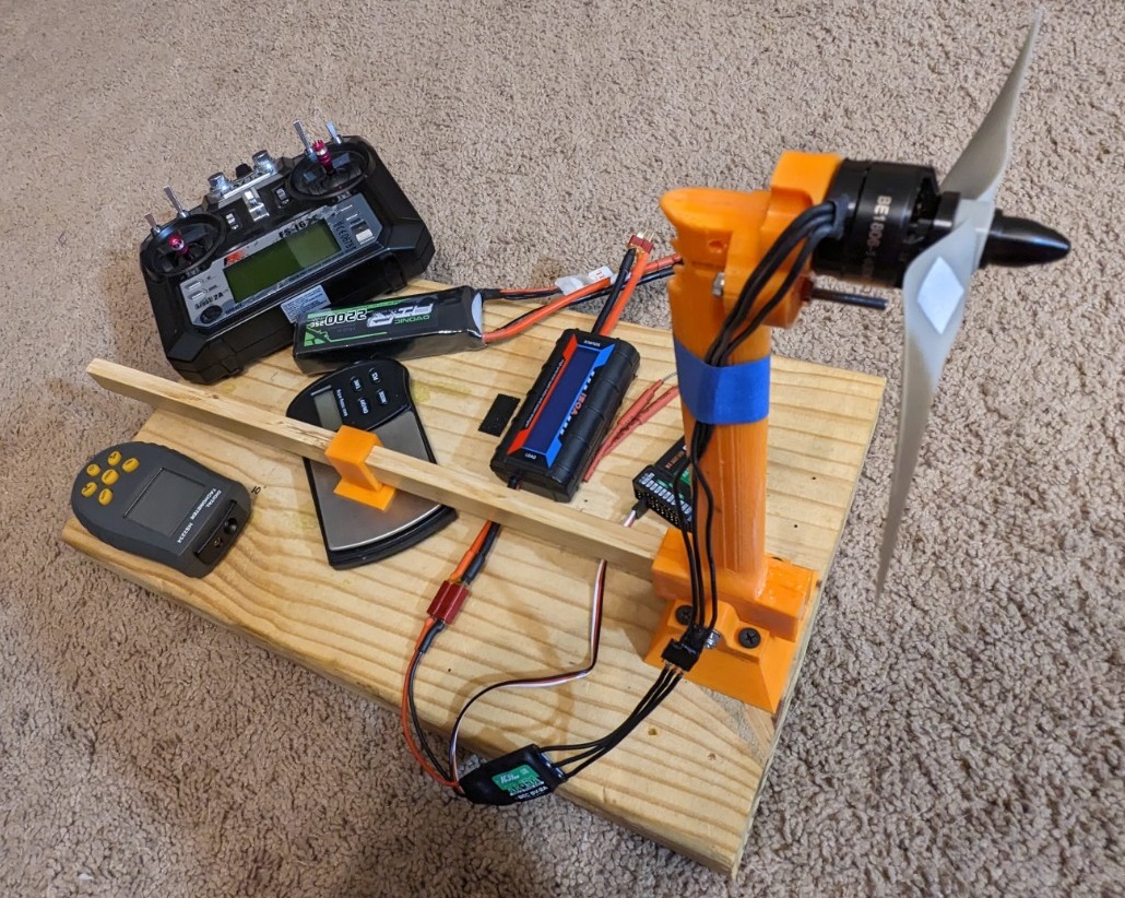
I want to design a folding, geared propeller. For this experiment, I'll be using a Flash Hobby BE1806, 1400KV motor and 3S power. I have two stock propellers (6x3.5 Orange, 6x4 Grey) that are (I guess) the typical for this motor.

I'll benchmark both of these to get a baseline static thrust using my Dynamometer.

I want to design something like this... folding, geared propeller.

What I'm looking for:
I'll know the motor RPM, current draw and thrust using the two baseline propellers. I know that if I have a reduction gear ratio, I can swing a bigger propeller and/or a different pitch propeller. The two things I'm looking for are:
(1) As long as I stay in the linear range of a propeller's airfoil, I'm thinking that power required should be linear WRT pitch angle. K = Pitch * rpm

(2) Knowing that drag on a foil is a function of velocity squared, and velocity is a linear function of diameter, I'm guessing.
K = Diameter * rpm^2.
What I'm coming up with in my simplistic concept is K = Pitch * Diameter * RPM^2 should be a first cut estimate that I'd print up and see how it works. If it draws too much power, I reduce the pitch or diameter or vice versa, if I'm not using enough power, I up one or the other.
I want to design a folding, geared propeller. For this experiment, I'll be using a Flash Hobby BE1806, 1400KV motor and 3S power. I have two stock propellers (6x3.5 Orange, 6x4 Grey) that are (I guess) the typical for this motor.

I'll benchmark both of these to get a baseline static thrust using my Dynamometer.

I want to design something like this... folding, geared propeller.

What I'm looking for:
I'll know the motor RPM, current draw and thrust using the two baseline propellers. I know that if I have a reduction gear ratio, I can swing a bigger propeller and/or a different pitch propeller. The two things I'm looking for are:
- Knowing the diameter, rpm and pitch it's pretty simple Math to determine the theoretical maximum speed of the plane. However, from a practical standpoint with scale issues and DIY propeller issues, what kind of slip percentage should I use? IOW... will the actual maximum speed of the plane be 50% of the theoretical or 95%?
- What would the equation look like to try to compare apples and oranges of different propellers? I'm just looking for a ballpark equation so I can say something like... "With a 1:3 gear reduction, I can swing a 10x6 propeller and the motor will be spinning the same speed and using the same current as with the 6x3.5.
(1) As long as I stay in the linear range of a propeller's airfoil, I'm thinking that power required should be linear WRT pitch angle. K = Pitch * rpm
(2) Knowing that drag on a foil is a function of velocity squared, and velocity is a linear function of diameter, I'm guessing.
K = Diameter * rpm^2.
What I'm coming up with in my simplistic concept is K = Pitch * Diameter * RPM^2 should be a first cut estimate that I'd print up and see how it works. If it draws too much power, I reduce the pitch or diameter or vice versa, if I'm not using enough power, I up one or the other.
Last edited: