Help! DIY Multistage Ducted Fan

Mid7night

Jetman
Mentor
Looks really good, for a start!

If possible (I don't know your printing constraints); Round the leading edges of the rotor and stator blades, and sharpen the trailing edges. Avoid blunt or bluff faces whenever possible.

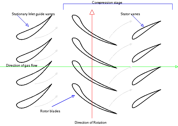
Also, if I'm interpreting your flow going from right to left and clockwise rotation as viewed from the aft looking forward; You want to reverse the curvature of the stators. You want the leading edge of the stator to be closely aligned with the angle of the flow coming off the preceding rotor, and then curve to straighten the flow more for the next rotor: (in this picture the flow is left to right)

Axial-flow-compressor.png
 

Akkupack

New member
Okay, thanks. Yeah, the stators have to be reversed now that I think about the airflow a bit more.

The reason for the blunt edges is simply because the parts are quite small and ABS has a tendency to shrink a lot during printing (I don't have a heated chamber) so I have to maximize the surface contact between the part and the hotbed. The most I can do is sharpen the leading edges and that's pretty much it.

The rotors are made in OpenSCAD with a generator I found online, useful for making the blade pitch higher, closer to the hub and also saving me modelling work when doing the different pitched rotors. Because of this way of making them, it will be difficult to round the leading edges without modifying the generator code, which I'll have to analyze first. Therefore I think that I'll leave that for later and just try make the 3rd design tomorrow and begin printing it for testing. I managed to fit the axle to a dremel quite well so I can see how much air it can blow.
 

Mid7night

Jetman
Mentor
Great! I understand the constraints of 3D printing, especially FDM. Do what you need to do to make the print successful first, then you can refine it later.

You could also probably reduce the number of rotor blades you have by about 50%, given the small diameter you're working with, or you could print a couple with varying blade counts and compare the results!
 

Akkupack

New member
Update: I've made the stators essentially be a flipped rotor that has a pitch that is the average of the pitch of the rotors next to the stator. Didn't test those, since I didn't print them yet. Reduced the no. of rotor blades from 16 to 8, and nozzle stator blades from 8 to 4. The nozzle had also been made a bit longer and now contains one end of the rod with a bearing inside. Besides, I've also added a sleeve to it that is supposed to fit around the metal tube (to fix the nozzle on the rest of the assembly), however I've noticed that I can straight up use the sleeve instead of the tube as a nacelle and I was thinking that I should make little holes inside of the sleeve and make the stators a bit bigger. The stators would have their blades wedged inside of the holes in the sleeve so they stay firmly fixed. The sleeve will split in half to make this possible, and mount back with maybe screws. I'm thinking that the small irregularities and damage I've caused to the aluminium tube somehow made it unbalanced, but there's also the fact that it's much easier to use the sleeve as a nacelle since I have it in CAD exactly as it is in reality, unlike the tube.

What I did test so far was the nozzle with its sleeve, and inside, rotor 1 and rotor 2 (40° and 47.5° blade angle respectively, with rotor 1 closer to the inlet), nothing else. No parts have had any acetone polishing so surface drag would be significant. I hooked it up to my dremel and turned it to 10krpm. I had to hold the nacelle in a very specific position due to the small clearances in the design and also because it was held in only one bearing. Vibrations were quite significant but it was able to blow about as much air as a medium-strength human blow. I'm not sure about why the vibrations are there, but I did notice that the crappy nuts I used weren't quite holding the bearing perpendicular to the rod as it was supposed to be held, which caused the nacelle to vibrate a lot when spinning. In the meantime I've ordered a bunch of (hopefully) high quality stainless steel nuts. The vibrations could also be from a poorly calibrated 3D printer but... I kinda refuse to believe that is the cause...
 

Akkupack

New member
Not really.
I've got my nice stainless steel nuts and new, smaller bearings. The vibrations were also due to my improvised axle - dremel connection, now it's fixed. I've decided on printing a better shell and using acetone to smooth it to perfection. It will just slightly increase the mass, but not too much, so, whatever. Nothing more other than this and more planning.

The reason for the lack of updates is mainly due to having other projects involving the printer, on a deadline, which means that said projects are higher priority by default. I should be able to resume the previous work speed in a week or two.
 

Akkupack

New member
Wow, time flies. So far, I've made a vapor smoothing chamber and improved myself in the art of vapor smoothing the thin blades of the thruster. Also, I've further reduced the blade count from 8 to 6 to decrease drag, increased the rotor diameter to 30mm (including tolerances) and settled on a specific design of the shell (essentially two sides held together and to the plane with four screws, printed with the exterior side facing downwards so the connection between the two sides isn't affected by ABS shrinkage, and also so the interior side is as smooth as top layers of a 0.1mm layer 3D print can be). My printer has received upgrades as well, which also took a while to install.

Now, I was thinking of making a slight sort of a de Laval nozzle, more towards an aerospike, I guess, incorporated in the design of the exhaust nozzle. I mean, the spike inside of the exhaust nozzle could have such a shape so the cross section area of the airflow mimics the cross section of a de Laval nozzle. I'm thinking of this, since maybe the relatively high pressure that the final design could make, can be turned into higher exhaust speed at the exhaust. Or maybe it's a really dumb idea.

By the way, here is a lengthwise section of the nozzle, showing the "spike" I was talking about. The hole inside the spike on the left is meant for a bearing and a hex nut holding the axle on the bearing.
1561400977777.png


Update: I've figured the vibration problem out, as it seems. The reason was because of the rotors: turns out that their flat surfaces held by the nuts wasn't perfectly perpendicular to the axle, which means that once I tightened the nuts to said surfaces, the nuts would also turn a little, and when the bearing is tightened in aswell between said nut and another nut, it also got that slight angle, which is obviously not good. I've fixed it by simply spacing the nuts holding the bearing from the nuts holding the rotor; this way, the bearing nuts don't get infected with the flawed angle. It seems to be so much better now. Really happy how it spins vibration free. I've just tested it on the dremel, the only (much less intense) vibrations come from an accidental bending of the axle, but it isn't that big of a deal at this phase of the project, being very manageable.
 
Last edited:

Akkupack

New member
I am very interested in this topic. Any progress?

Regards,
Joe T.

Hi, not any worth posting here. Since the last post, I've gave priority to other, more important business. Then, school started, and right now it's starting to tone down for the winter holidays, so maybe I'll put more work into this around this time.

To be honest, I'm kind of anxious of the fact that I won't be able to make it produce a meaningful amount of thrust. But maybe I just don't really know the true capability of a small RC brushless. Anyway, we will find out.