Lance Nordby
Member
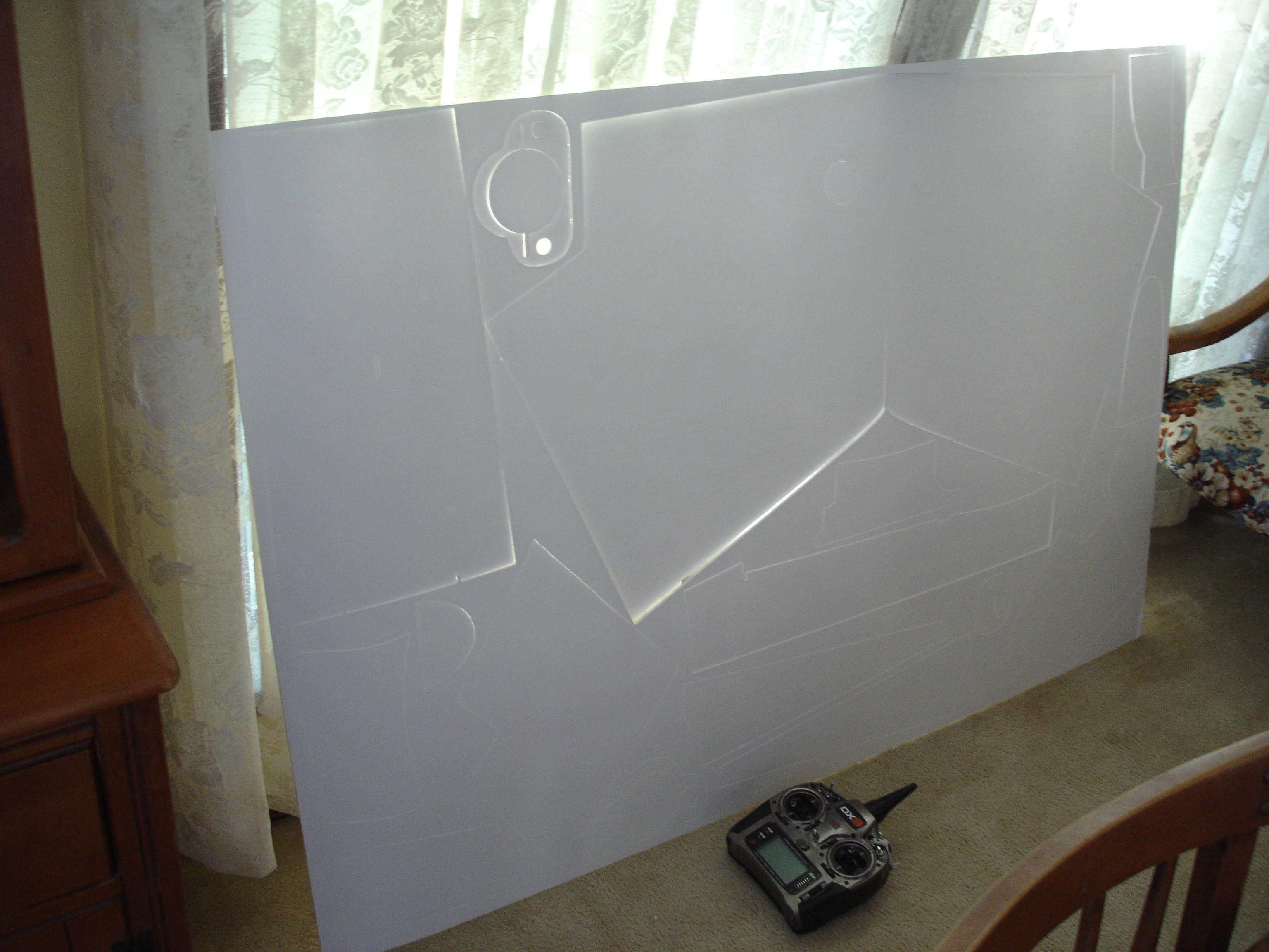
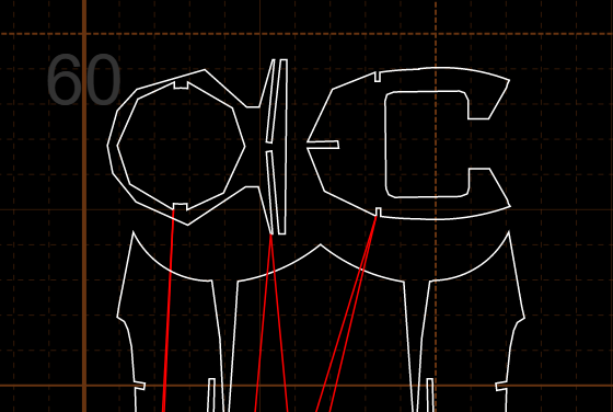
The machine managed to get through three each of the first sheet. Now on the second sheet it's having a lot of issues with getting all the way through the job without stopping or trying to run out of bounds.
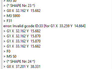
All the arcs are converted into splines and that helped but it's still choking on that invalid ID:33.
I think I've averaged about 10 trial runs for each successful sheet so far. It's getting old. Is anyone else trying to go from a 3D model to dxf to gcode? Or is everyone drawing in Inkscape?
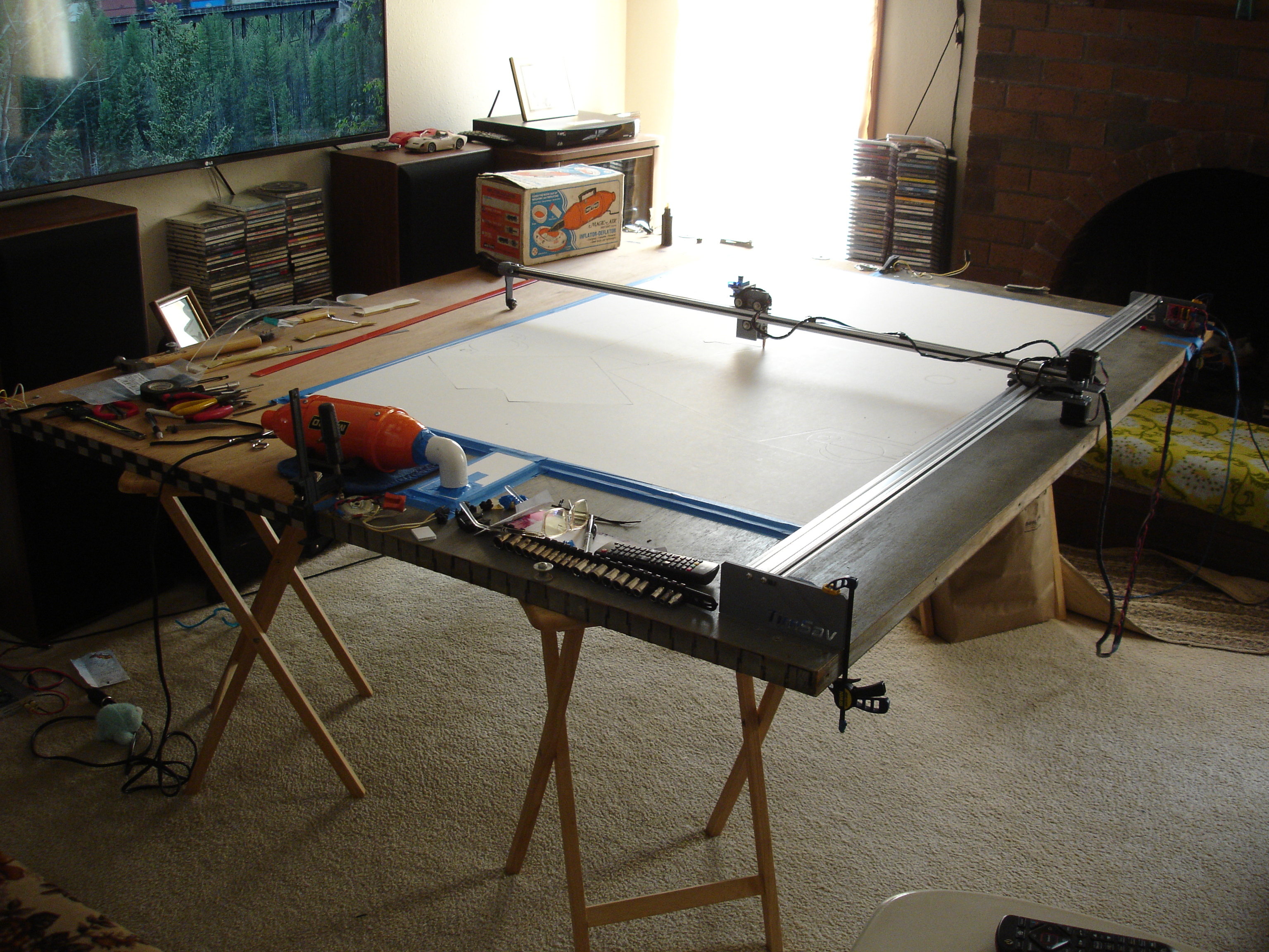
The machine cuts great when the software works.
All the arcs are converted into splines and that helped but it's still choking on that invalid ID:33.
I think I've averaged about 10 trial runs for each successful sheet so far. It's getting old. Is anyone else trying to go from a 3D model to dxf to gcode? Or is everyone drawing in Inkscape?
The machine cuts great when the software works.

")