ERC TimSav - Cheap DIY CNC Foamboard Cutter

LitterBug

Insanely Addicted Techno Geek Legendary Member
Moderator
I agree with Dudley1001

Also, make sure your home switch, rollers, and whatever the switch touches are not loose. Loose parts can cause inconsistant homing. I recently readjusted the rollers on one of my 3D printers because there was just enough slop to cause unwanted movement i the nozzle and print bed.

Check also for a home all axis GCODE like G28. That should really only be needed at the start of a print if at all. I have Lightburn set up to NOT home at the start, but rather start wherever the head is. If I ever build a better bed with alignment marks or rails, I may change to using homing.
 

Destructor

New member
If its happening after going to the home position, I assume when switching from score to cut, then I would be looking at if the unit is hitting something in the home position. This could be coming up against the belt holder on the y or the frame pieces on the x direction. If its hitting something, it will cause the motors to jump a step or more and throw things off. The other thing you can do is to edit your gcode to remove the lines that send it to home, totally unnecessary. You can open the gcode in notepad and looks for a line like "G0 X0 Y0" and delete it out . Rather than notepad I use "notepad++" for my editing Notepad++ as it does a better job. If you are using the method that Eric shows how to generate the gcode, there are better methods out there. If you are on facebook there is a long running page with some other plug-ins for inkscape that do a wonderful job. I haven't kept up with the versions of the plug-in as my machine doubles as a laser so I use a different firmware and Laserweb4 for run the unit and also make the gcode. I am a tinkerer at heart and mine is running fluidnc on a MKS Tinybee 3d printer board rather than GRBL these days.

I don't think this is a problem with the CH340 as it causes a reboot not what you are describing

Did you try the vref adjustment and changing the $1=255 ?
Ive adjusted the vref from the start, so i didnt do it again. I tried the $1=255, but my drivers seem to be getting quite hot, so i didnt keep it for long. Maybe I'll try with a fan. I think it is a software problem(not sure though)
The grbl controller software seems kinda sketchy to me already, and I'm not exactly happy with the Inkscape extension only working with older versions. If there are other G-code generation and control options, I am open to trying those. I also heard that there are other controller options othere that arduino uno, so if they're not too expensive, I can try those too, if switching improves the situation.
I was thinking it would be good if I could have something like OctoPrint set up for the CNC. It would be very convenient, as connecting to my laptop to cut is a pain for me.
 

Merv

Moderator
Moderator
... connecting to my laptop to cut is a pain for me.
I use this off line controller on mine. I generate the Gcode file, stick it in the controller & hit start.


Here is how to hook it up.
 

Mr NCT

VP of SPAM Killing Striving for Mediocrity
Moderator
Soooo....
I found a post on the ERC fb group that shows how to use an Arduino nano to turn the motor on and off using the coolant on/off command. The code and wiring are on github: https://github.com/DavidJJ/TimSav_M...vIgngEmNEZNevCLi-0_aem_XBurx_01rJtPJCqG5IzmZQ

The wiring I can handle but I'm a noob with arduino. How do I load this code to the nano?
BTW - I've got extra potentiometers and resisters for this project if you want to try it. I've might have a nano left also if I don't fry the first one.
 

Mr NCT

VP of SPAM Killing Striving for Mediocrity
Moderator
Soooo....
I found a post on the ERC fb group that shows how to use an Arduino nano to turn the motor on and off using the coolant on/off command. The code and wiring are on github: https://github.com/DavidJJ/TimSav_M...vIgngEmNEZNevCLi-0_aem_XBurx_01rJtPJCqG5IzmZQ

The wiring I can handle but I'm a noob with arduino. How do I load this code to the nano?
BTW - I've got extra potentiometers and resisters for this project if you want to try it. I've might have a nano left also if I don't fry the first one.
I guess I finally asked google the right question - How to convert a .cpp file to a .ino file? I'll include the answer since it seemed to work.

"Here is a step-by-step guide:
  1. Rename the File: Change the file extension of your main C++ file from .cpp to .ino. This file must be in a folder with the exact same name as the file itself.
  2. Remove #include "Arduino.h": The Arduino IDE's preprocessor automatically adds necessary Arduino core includes (like Arduino.h, setup(), and loop()) during compilation for .ino files. Including it manually in an .ino file can sometimes cause compilation issues.
  3. Ensure setup() and loop() Functions are Present: Your code must contain the standard void setup() and void loop() functions, as these are the entry points the Arduino environment expects.
  4. Manage Function Prototypes: The Arduino IDE automatically generates function prototypes for functions defined within a .ino file. This means you typically do not need to manually declare a function before it is called, provided all functions are in the main .ino file or other .ino files within the same sketch folder.
  5. Handle External Libraries:
    • If your original C++ project uses external libraries (e.g., from a platformio.ini file if using PlatformIO), you need to manually install these libraries using the Arduino IDE's built-in Library Manager.
    • Ensure any #include statements for these libraries in your .ino file use angle brackets (#include <LibraryName.h>) if they are in the Arduino libraries folder, or double quotes (#include "LibraryName.h") if they are custom libraries within your project folder."
 

Mr NCT

VP of SPAM Killing Striving for Mediocrity
Moderator
Soooo....
I found a post on the ERC fb group that shows how to use an Arduino nano to turn the motor on and off using the coolant on/off command. The code and wiring are on github: https://github.com/DavidJJ/TimSav_M...vIgngEmNEZNevCLi-0_aem_XBurx_01rJtPJCqG5IzmZQ

The wiring I can handle but I'm a noob with arduino. How do I load this code to the nano?
BTW - I've got extra potentiometers and resisters for this project if you want to try it. I've might have a nano left also if I don't fry the first one.
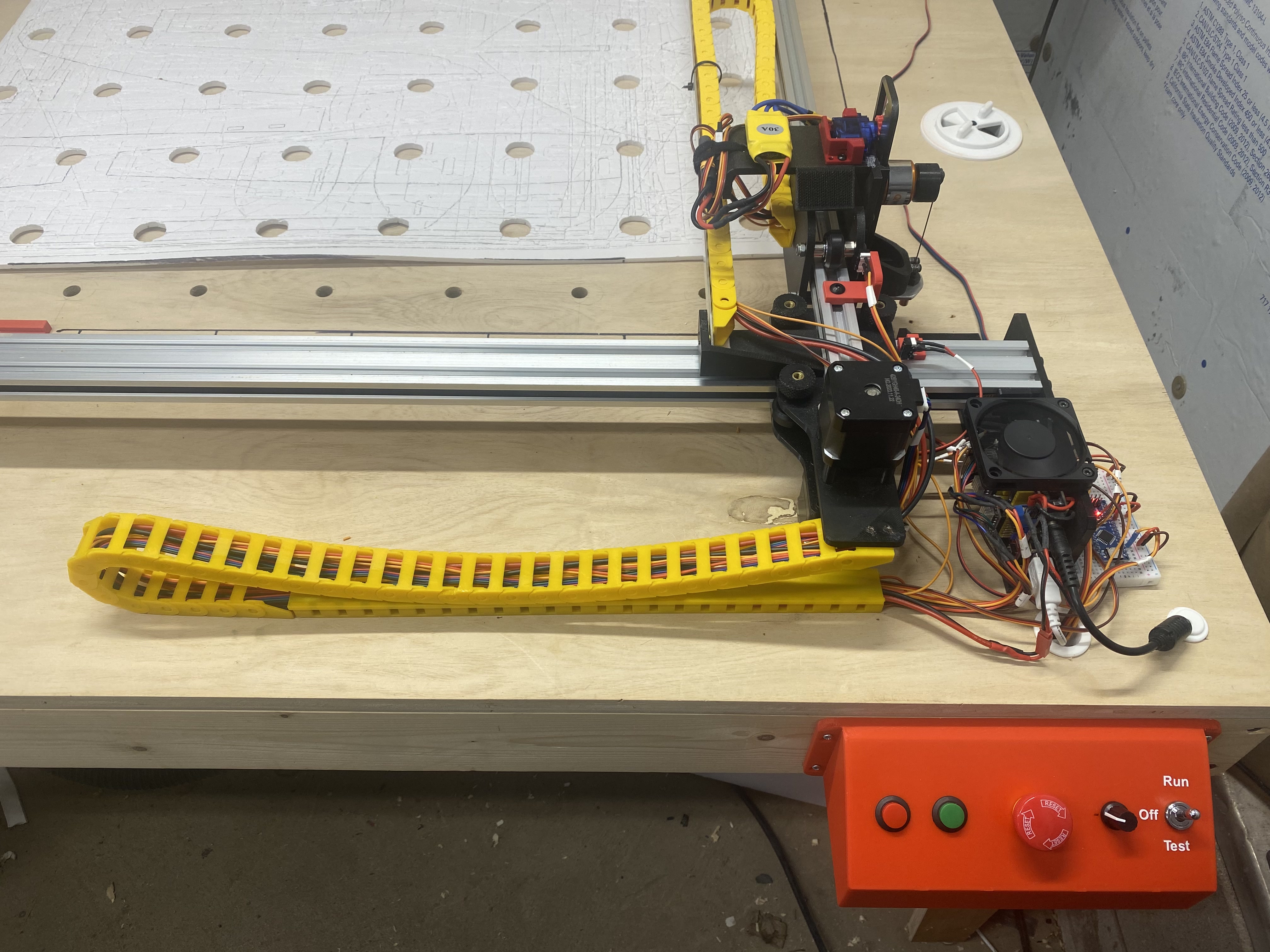
Just finished this mod and it works great. Took the opportunity to clean up the controls and put a "real" machine control panel on with pause, resume, E-stop, motor speed pot and motor control 3 position toggle.

IMG_019367.jpg
 

diiity

New member
Hello,

I'm cutting 3, 6, and 9mm Depron fibers.

I'd like to know the feed rates for the X and Y axes, as well as the rotation speed of the brushless motor.

Thanks

Diiity

Bonjour,

Je coupe des fibres Depron de 3, 6 et 9 mm.

Je voudrais connaître les vitesses d'avance des axes X et Y, ainsi que la vitesse de rotation du moteur sans balais.

Merci

Diité
 

Mr NCT

VP of SPAM Killing Striving for Mediocrity
Moderator
Here's a schematic of my current set up. Modifications from original are: -X & -Y homing limit switches, pause and resume push buttons, needle motor controlled by Nano with speed set by remote pot, an E-Stop button. All the info was scattered, now it's all in one place. I've included sources for the add-on parts.

Just learning KiCad - what a cool free program!
 

Attachments

  • ERC TimSav w mods.pdf
    181.6 KB · Views: 0

Mr NCT

VP of SPAM Killing Striving for Mediocrity
Moderator
Hello,

I'm cutting 3, 6, and 9mm Depron fibers.

I'd like to know the feed rates for the X and Y axes, as well as the rotation speed of the brushless motor.

Thanks

Diiity

Bonjour,

Je coupe des fibres Depron de 3, 6 et 9 mm.

Je voudrais connaître les vitesses d'avance des axes X et Y, ainsi que la vitesse de rotation du moteur sans balais.

Merci

Diité
Sorry, I have never cut Depron. I think it would cut very easily with the needle cutter. The hard part of cutting foam board is the paper. I normally run the motor at ~ 10,000 rpm. Cutting only part way (one thickness of paper) at 1400 mm/min, all the way through at 900. Since Depron does not have paper I think you could cut it at the higher speed.
 

Dudley1001

Active member
Hello,

I'm cutting 3, 6, and 9mm Depron fibers.

I'd like to know the feed rates for the X and Y axes, as well as the rotation speed of the brushless motor.

Thanks

Diiity

Bonjour,

Je coupe des fibres Depron de 3, 6 et 9 mm.

Je voudrais connaître les vitesses d'avance des axes X et Y, ainsi que la vitesse de rotation du moteur sans balais.

Merci

Diité
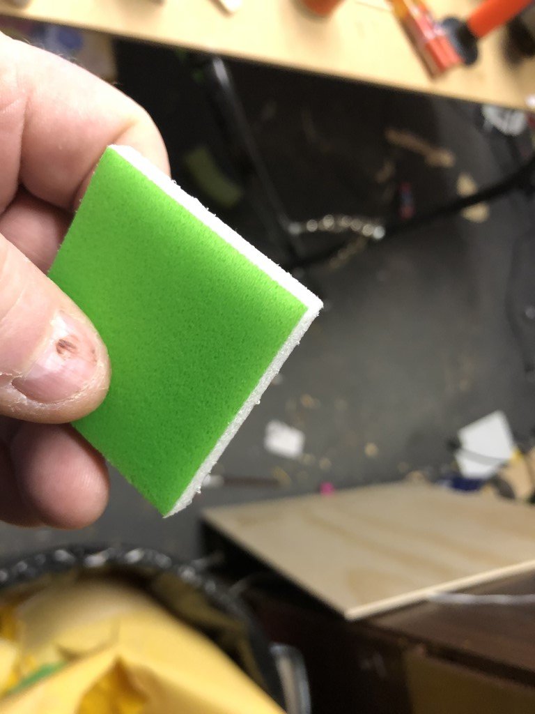
I cut depron type foam and don't really worry about the needle speed and just go about 75% speed on the servo tester. Most of my cutting is at 800-900mm/min and it cuts better than a laser. You may have problems on the 9mm depron as it would be pretty much the maximum depth of the flywheel stroke. The picture is a sample cut on the 6mm depron type foam I found at a dollar store, no paper just some terrible neon paint on one side.
 

Attachments

  • IMG_1225 (Medium).JPG
    IMG_1225 (Medium).JPG
    85.5 KB · Views: 0

Mr NCT

VP of SPAM Killing Striving for Mediocrity
Moderator
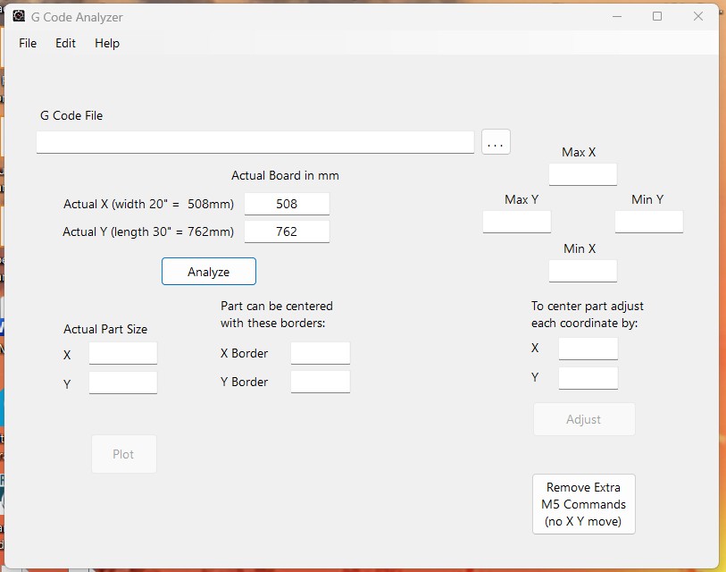
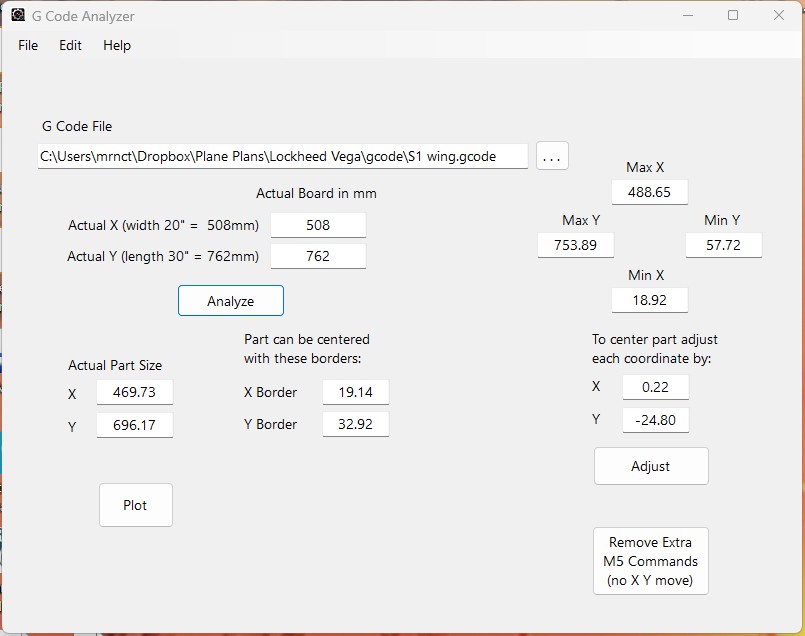
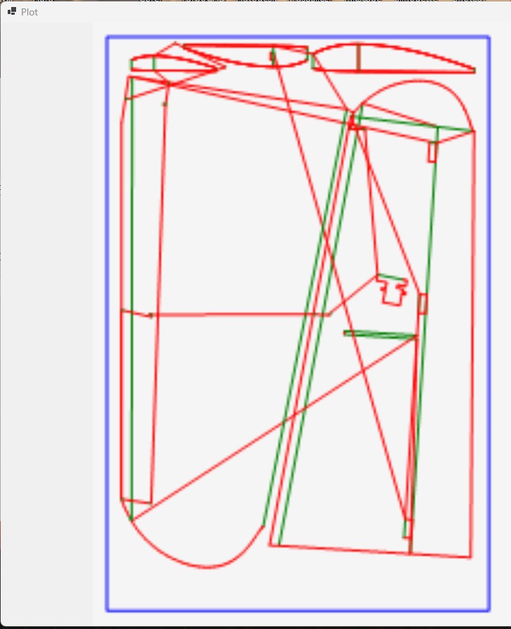
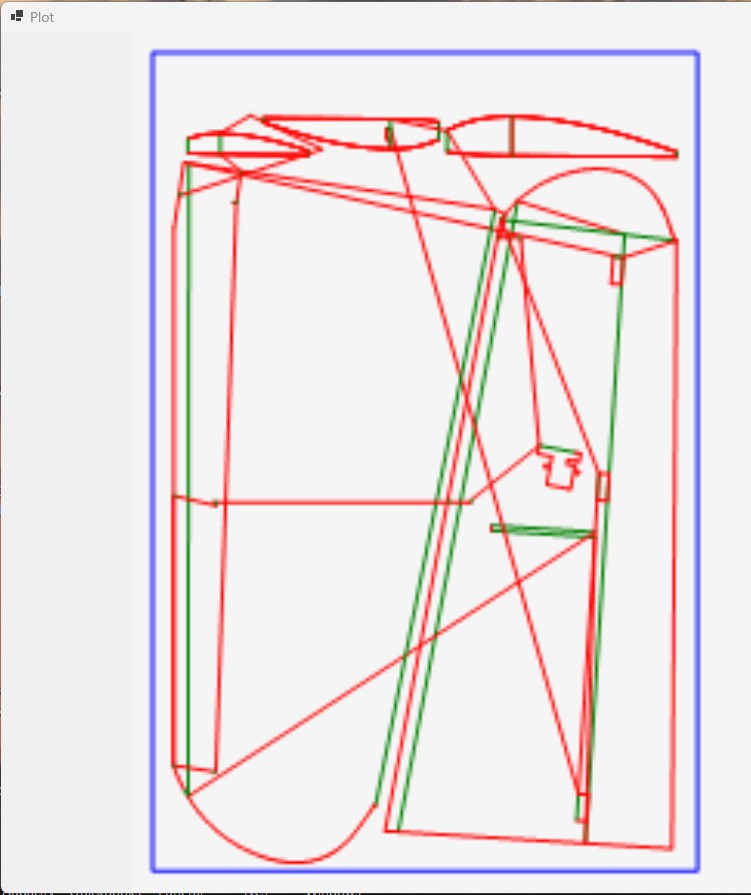
I've written a G Code analyzer aimed at the TimSav. It allows you to put in the actual foam board dimensions, analyze a gcode file for total physical size and either automatically center it or change the margins to move it around on the sheet. It also has a plot of the cuts. If you try it let me know what you think. (download and run the .msi file)


Mr NCT

VP of SPAM Killing Striving for Mediocrity
Moderator
I've written a G Code analyzer aimed at the TimSav. It allows you to put in the actual foam board dimensions, analyze a gcode file for total physical size and either automatically center it or change the margins to move it around on the sheet. It also has a plot of the cuts. If you try it let me know what you think. (download and run the .msi file)

I forgot that it can also remove the extraneous M5 needle raises where there is no X, Y, or G change from one line to the next. Here are some screen shots:

Screenshot 2026-05-02 163001.jpg Screenshot 2026-05-02 163106.jpg Screenshot 2026-05-02 163149.jpg Screenshot 2026-05-02 163310.jpg
 
Last edited:

Mr NCT

VP of SPAM Killing Striving for Mediocrity
Moderator
I forgot that it can also remove the extraneous M5 needle raises where there is no X, Y, or G change from one line to the next. Here are some screen shots:

View attachment 258005 View attachment 258006 View attachment 258007 View attachment 258008
I promise to stop messing with this for awhile :ROFLMAO: . I fixed some display problems and added cut simulation. Really, I promise I'll keep my hands off of it for awhile.


Mr NCT

VP of SPAM Killing Striving for Mediocrity
Moderator

Mr NCT

VP of SPAM Killing Striving for Mediocrity
Moderator
I was getting inconsistent cuts and scores on the erc so...

I went completely OCD on it for most of two days. I went WAY overboard for foam board. I found that the vacuum table that I thought I'd built braced well enough to stay level didn't, it bowed down in the center about 2mm - so I put a leg under the center of the table with an adjuster on it. Then since I had space cleared around it to work I got out the dial indicator and checked the height of the X beam at all four corners of the table and found that they varied as much as 1.5mm - so I shimmed them to match the highest one (plus or minus 0.05mm). Then I ran an accuracy test and found the Y to be off 10mm over 700mm - so I adjusted $101and got it within 1mm.

Once done the cuts were perfect and such a sense of accomplishment!
 

Foamforce

Elite member
I was getting inconsistent cuts and scores on the erc so...

I went completely OCD on it for most of two days. I went WAY overboard for foam board. I found that the vacuum table that I thought I'd built braced well enough to stay level didn't, it bowed down in the center about 2mm - so I put a leg under the center of the table with an adjuster on it. Then since I had space cleared around it to work I got out the dial indicator and checked the height of the X beam at all four corners of the table and found that they varied as much as 1.5mm - so I shimmed them to match the highest one (plus or minus 0.05mm). Then I ran an accuracy test and found the Y to be off 10mm over 700mm - so I adjusted $101and got it within 1mm.

Once done the cuts were perfect and such a sense of accomplishment!
Very nice!

Are you going to port the bed leveling sensor functionally over from 3d printers next? 🙂
 

Mr NCT

VP of SPAM Killing Striving for Mediocrity
Moderator
Very nice!

Are you going to port the bed leveling sensor functionally over from 3d printers next? 🙂
What a GREAT idea! It could compensate for the waviness of the foam board. Maybe I could hook up an autoloader/unloader to it, too!