Experimental Arduino RC Plane Build Log

Would you use the hardware and/or software designed as part of this project for your own RC planes?

  • Yes

    Votes: 10 100.0%
  • No

    Votes: 0 0.0%

  • Total voters
    10

Power_Broker

Active member
Im glad there is somebody out there who understands this....because I have zero clue whats going on

I apologize if my explaining isn't as clear as it should be. One of the reasons for making this thread is to help teach those in the hobby how things work on a lower level, so making things easy to understand is important to me. If you (or anyone else) has any questions or would like clarification on anything, I would be more than happy to answer them.
 

JLJ

New member
@Power_Broker Thank you for sharing!

I've spotted a pitot tube, your project looks awesome!

"This next plane will be my first to have an on board pitot tube and pressure sensor for airspeed data. This will provide useful flight control feedback when implementing autopilots (especially autolanding features). "

Regarding autolanding features do you have any specific idea? That can be really cool.
 

Power_Broker

Active member
@JLJ No problem! I'm glad you like it so far.

I have a few ideas in the infant stage in terms of autolanding features. One would be a homemade ILS using scratch made lowish frequency radios, directional antennae, and simple on board RSSI (Receive Signal Strength Indicator) circuitry. This alone can be considered a full scale/serious hobby project, but for my purposes, it will be a supporting feature. I also want to use GPS waypoint flying to setup the landing pattern on final approach. No matter what the autolanding solution will look like, I will still need airspeed data from my pitot tube, Euler angles from my IMU, and altitude data from my LiDAR. The sensor fusion for this part of the project will be rather complex - here's hoping that it all works out.

This feature/set of features aren't projected to be completed (or even started) for at least another 6-12 months. I first have to finish the base plane, get a good maiden flight in 100% manual mode, complete several manual test flights (in order to record vehicle telemetry and controller inputs), analyze the data, develop a simple level and hold autopilot, improve the autopilot for turns, and lastly achieve automated GPS waypoint flying. Only then will I start working on autolanding.
 

JLJ

New member
@Power_Broker Thank you for your reply. It seems a really enjoyable project!
Yes, my profile picture shows an 8mm diameter DIY pitot-static probe. The very same model of the rightmost in the following picture.
You find a sketch of the probe in this thread.
I have some hands-on experience on basic air data topic; regarding fly at low altitudes, I tried GPS + Baro sensor fusion with an EKF.
picture-1080x380.jpg
 

Power_Broker

Active member
Woah, that's pretty cool! What exactly were you testing/measuring in that picture?

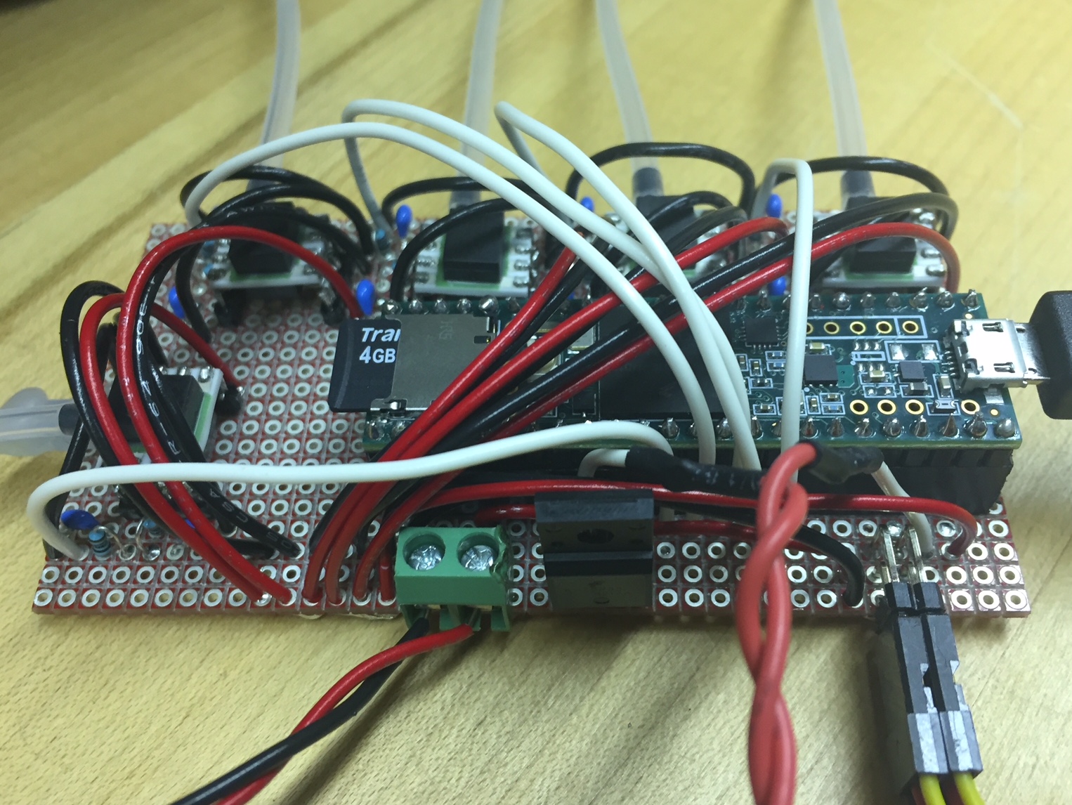
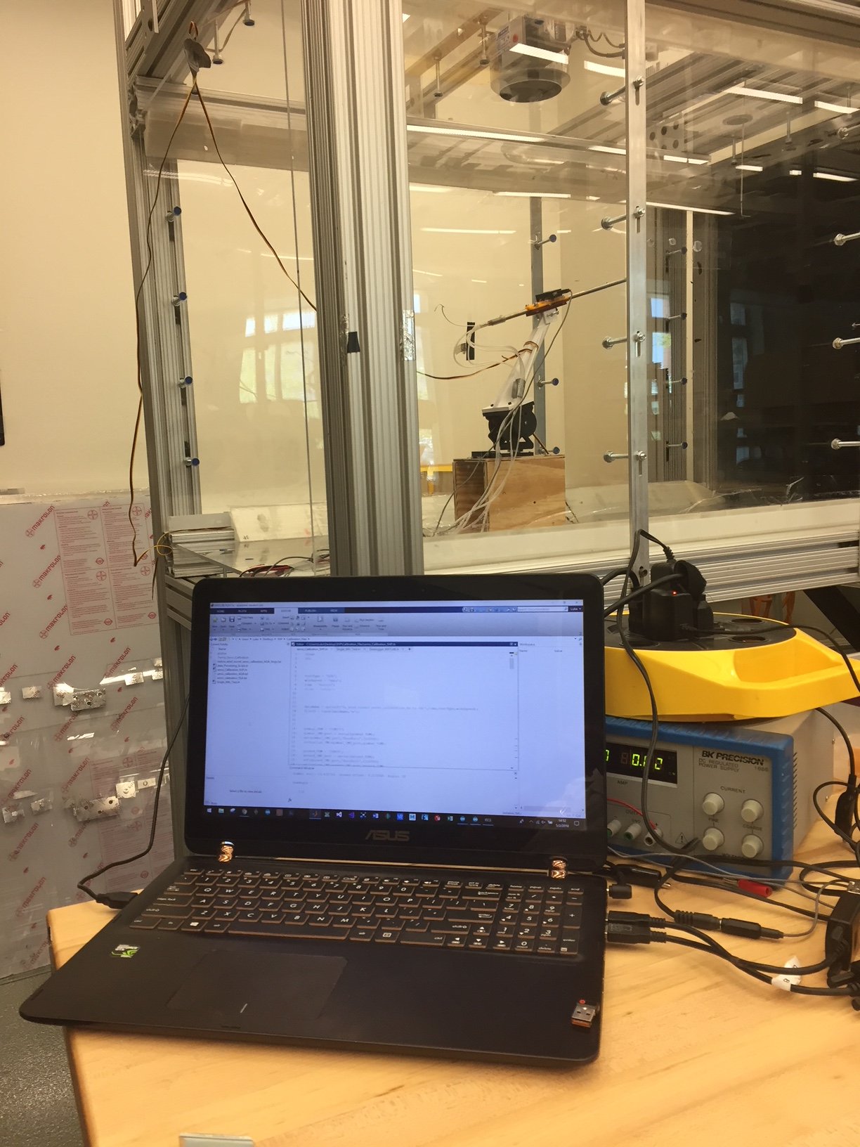
During my last semester, I had a chance to do some research with the Virginia Tech Nonlinear Systems Laboratory with a 5-Hole Probe. I made an air data computer and wind tunnel calibration rig for it. Attached is some of the documentation for the project - I think you would be quite interested in the setup/data. If you'd like more info, I can find it out for you.


IMG_2404.jpg
IMG_2517.JPG
 
Last edited:
  • Like
Reactions: JLJ

JLJ

New member
That's a lot! I see your calibration setup, excellent indeed.
Regarding the 8 mm probe, it was tested at different AOA and compared with other commercially available probes; at a glance, the probe seems to handle well a moderate AOA/AOS (nothing to be surprised of). You can read the following report, not by me, in this link; you find the tested probes at chapter 5 and BAD probe at 5.2.

I've fiddled with mechanical vanes and MHP. For Basic Air Data I've tested (early stage test) a straightforward 3 Holes MHP probe intended for AOA measurement only (the probe have an 8 mm diameter 3D printed tip); No 5/7 holes multi-hole probes were designed for the DIY project (nothing like Cobra nor Oxford probes). It seems too much for the DIY maker; Besides that MHP are alluring.
 

Power_Broker

Active member
Update 17.)

I know it's been a while, but life has been crazy lately :).

Some time ago I discovered this interesting piece of electronics: . It's basically a solid state relay switch that's rated for 6-60V and up to 120A and is controlled by a pushbutton. Although it is originally designed for electric skateboards, I'll have no trouble using it as a safety killswitch for my plane's motor. The only problem was that it doesn't come with built in connectors and new ones have to be soldered in manually. Here are some pics:

IMG_E3169.JPG
IMG_E3168.JPG

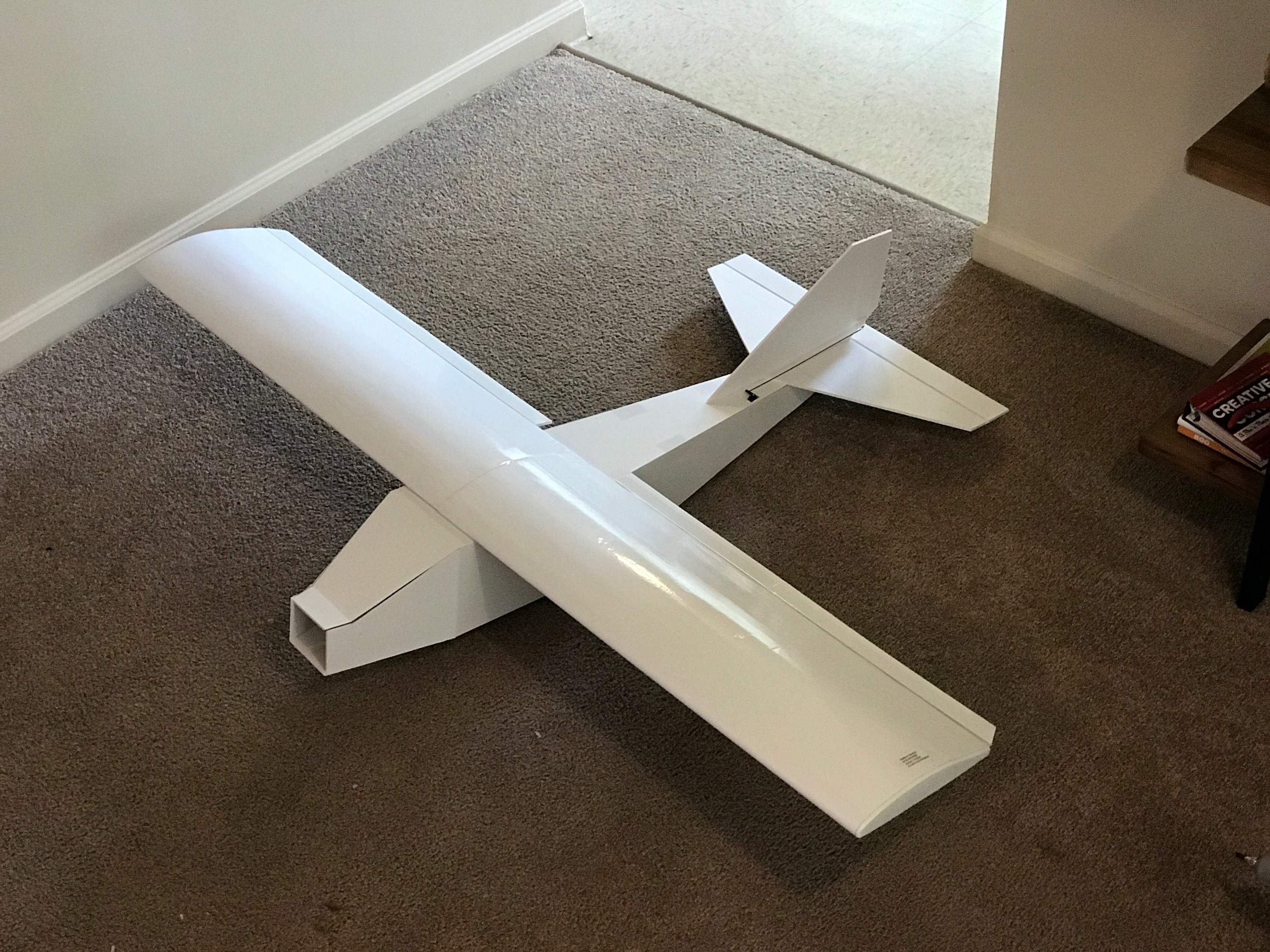
Not too long ago, a friend of mine offered to build a new custom airframe using foamboard for this project, so I decided to go with that instead of focusing on finishing my frame. I will finish my version of the frame at some point, but right now I'm going to stick with the lighter, custom foamboard plane. It has the same wingspan and chord (4ft with 1ft chord) and has a large amount of storage space inside the fuselage. The main advantages are that it is MUCH lighter and it is also a lot easier to access the internal avionics compared to my 3D printed plane. Here is a pic of my friend's design/build:

IMG_3190.JPG


After getting the frame, I started migrating all the electronics from the old frame to the new one. There weren't any major difficulties or differences in configuration except for better cable management (more zipties!) and the mounting of the LiDAR altimeter on the avionics box itself (which meant I had to cut a hole in the bottom of the plane - see pics). Speaking of which, here are some pictures of the electronics migration:

IMG_3220.JPG IMG_3218.JPG IMG_3217.JPG
IMG_3216.JPG IMG_3215.JPG IMG_3214.JPG
IMG_3213.JPG IMG_3212.JPG IMG_3210.JPG
IMG_E3208.JPG IMG_3207.JPG IMG_3206.JPG
IMG_3205.JPG IMG_3204.JPG


Also, there is a HUGE and exciting update on the ground station side. A few weeks ago I bought this joystick setup for VR flying in the game War Thunder (highly recommend btw), and got an idea. I realized that instead of designing and building my own controller hardware, I could get more realistic results and more controller inputs if I use the gaming joystick, throttle quadrant, and pedals.

The idea is to take all three of the devices and plug them into my laptop running a Windows C++ program (custom written mostly by yours truly) that takes in all the joystick data, processes it, and sends the plane commands via a USB radio. Right now I can still get away with using the XBees that I was using with the old setup, because I have some XBee to USB adapters (USB dongles). Here are some pics of the new ground station setup:

Amazon Link
81ENJBn-l4L._SL1500_.jpg
 
Update 17.)

I know it's been a while, but life has been crazy lately :).

Some time ago I discovered this interesting piece of electronics: . It's basically a solid state relay switch that's rated for 6-60V and up to 120A and is controlled by a pushbutton. Although it is originally designed for electric skateboards, I'll have no trouble using it as a safety killswitch for my plane's motor. The only problem was that it doesn't come with built in connectors and new ones have to be soldered in manually. Here are some pics:

View attachment 113377
View attachment 113379

Not too long ago, a friend of mine offered to build a new custom airframe using foamboard for this project, so I decided to go with that instead of focusing on finishing my frame. I will finish my version of the frame at some point, but right now I'm going to stick with the lighter, custom foamboard plane. It has the same wingspan and chord (4ft with 1ft chord) and has a large amount of storage space inside the fuselage. The main advantages are that it is MUCH lighter and it is also a lot easier to access the internal avionics compared to my 3D printed plane. Here is a pic of my friend's design/build:

View attachment 113375

After getting the frame, I started migrating all the electronics from the old frame to the new one. There weren't any major difficulties or differences in configuration except for better cable management (more zipties!) and the mounting of the LiDAR altimeter on the avionics box itself (which meant I had to cut a hole in the bottom of the plane - see pics). Speaking of which, here are some pictures of the electronics migration:

View attachment 113359 View attachment 113360 View attachment 113361
View attachment 113362 View attachment 113363 View attachment 113364
View attachment 113365 View attachment 113366 View attachment 113367
View attachment 113369 View attachment 113370 View attachment 113371
View attachment 113372 View attachment 113374


Also, there is a HUGE and exciting update on the ground station side. A few weeks ago I bought this joystick setup for VR flying in the game War Thunder (highly recommend btw), and got an idea. I realized that instead of designing and building my own controller hardware, I could get more realistic results and more controller inputs if I use the gaming joystick, throttle quadrant, and pedals.

The idea is to take all three of the devices and plug them into my laptop running a Windows C++ program (custom written mostly by yours truly) that takes in all the joystick data, processes it, and sends the plane commands via a USB radio. Right now I can still get away with using the XBees that I was using with the old setup, because I have some XBee to USB adapters (USB dongles). Here are some pics of the new ground station setup:

Amazon Link
View attachment 113380
Been following this project for a while but only just got a account a while back. This thing is awesome! Can't wait to see this get finnished. Safe flying.
 

Power_Broker

Active member
Oh, and one thing I forgot to mention: I printed a new mount for the LiDAR altimeter and CA glued it to the back of the avionics box. I then cut a rectangular hole in the bottom of the plane for the LiDAR to have a clear view to the ground. You can see it in the pictures, but I wanted that part to be clear to everyone.
 

Power_Broker

Active member
Here's a vid of me testing the plane with my simulator gaming joystick setup. I have Thrustmaster joystick, throttle, and pedals for VR flying in War Thunder and wrote a C++ program to control my plane with them.


I'll probably post the C++ code I'm running on my computer for the joystick if y'all want.
 

Power_Broker

Active member
Update 18.)

Had two test flights this past Monday. Both of them ended up in crashes due to corrupted radio information. The first crash didn't hurt the plane, but the second one ripped the nose section completely off - none of the electronics were harmed excepting the battery. Here's a vid of the final test flight:


I think the radio connection was intermittent due to insufficient power for the ground station. For the ground station, I was only using a 1000mah battery that was not even half charged. I believe that was the root cause because I didn't run into the problem during bench testing of the plane at home with bigger batteries. Also, corrupted packets occurred more often as the flight testing went on, suggesting that the battery was getting lower and lower.

A new plane and updated hardware/software will be coming soon!
 

Power_Broker

Active member
Random Note:

I like to listen to this playlist I made on YouTube while I work on my plane and other projects. Just in case y'all might enjoy it, too.
 

Power_Broker

Active member
Update 19.)

It's been a while since I've posted anything, but I've been making a lot of progress on a new plane since my last flight.

First off, my friend has graciously made a second and improved frame for me to use. I am, though, reusing the wings. The wings sustained minimal damage from the previous test flights.

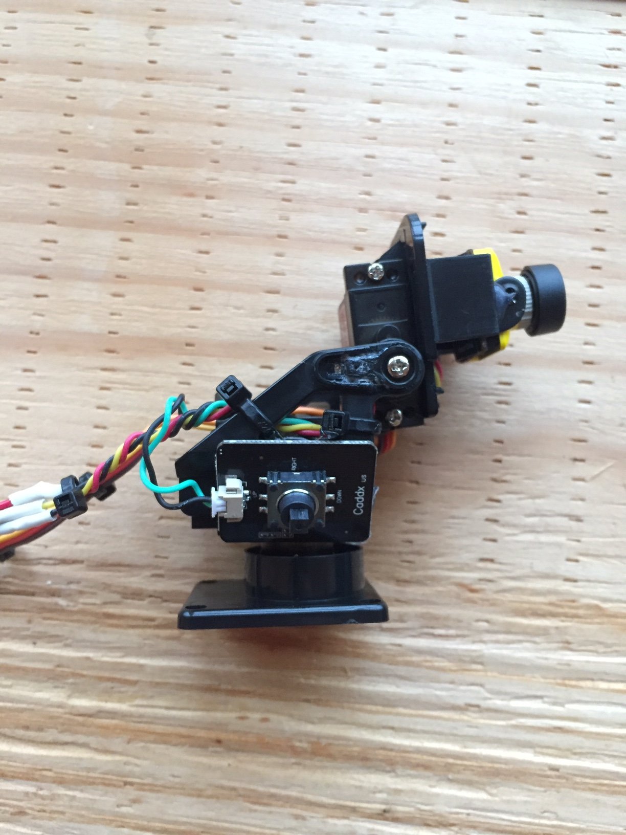
Also, I've completely overhauled the FPV system by redoing the wiring, adding a new camera, and making a servo gimbal for the camera. Although I haven't really used the FPV equipment much on previous planes, the final product will have full FPV functionality. I'm planning ahead and developing those features now. The new camera and the gimbal can be found here (camera) and here (gimbal). Here are some pictures of my setup:

IMG_3589.JPG


IMG_3590.jpg IMG_3591.JPG IMG_3592.JPG


Also, I added a second set of radios, added a battery low voltage buzzer circuit (on the plane avionics), and redid the on-board PCB. For the radios, I'm adding a pair of these 3DR telemetry radios, BUT... I'm using them for command and control from the hand controler (not telemetry). The old XBees will still be supported, but they will be communicating with a second ground station for sensor control and telemetry. The second ground station will be a laptop PC with my joystick setup and special C++ code. The types of things this second ground station might control would be the camera gimbal angles, bomb bay doors, PID tuning knobs, etc. etc. etc. The normal flying controls (ailerons, rudder, elevator) will still be controlled using the old hand controller (just with the 3DR radios instead of the XBees).

These new radios are a lot better than the XBees for a few reasons. Above all, the 3DR radios operate at lower frequencies (915MHz compared to 2.8GHz). They also are 500mW compared to the 60mW of the XBees. These two features alone allow the 3DR radios to have a much longer and reliable flying range. On top of all of this, the new radios have hard enclosures and high gain antennas (compared to the tiny wire antennas of the XBees).

Although some might say, "Wait, how can they work for command and control when they are advertised as telemetry radios?", the answer is that these radios don't care what message payload they are transferring. They simply transfer serial data from one radio to the other - exactly like the XBees. You just have to make sure your message payloads are constructed/deconstructed correctly in your software.

In order to use these radios, I'm using the TTL interface (5V, TX, RX, GND pins - NOT the USB interface). How I made this work was to take the micro JST connectors the radios come with, cut off one of the connectors, and soldered on a female JST-3S connector. Lastly, since the micro JST connectors easily come out of the radios - :mad: - I had to hot glue the connector into the radio while trying to keep the USB port accessible. Here's some pics:

IMG_3593.JPG IMG_3594.JPG

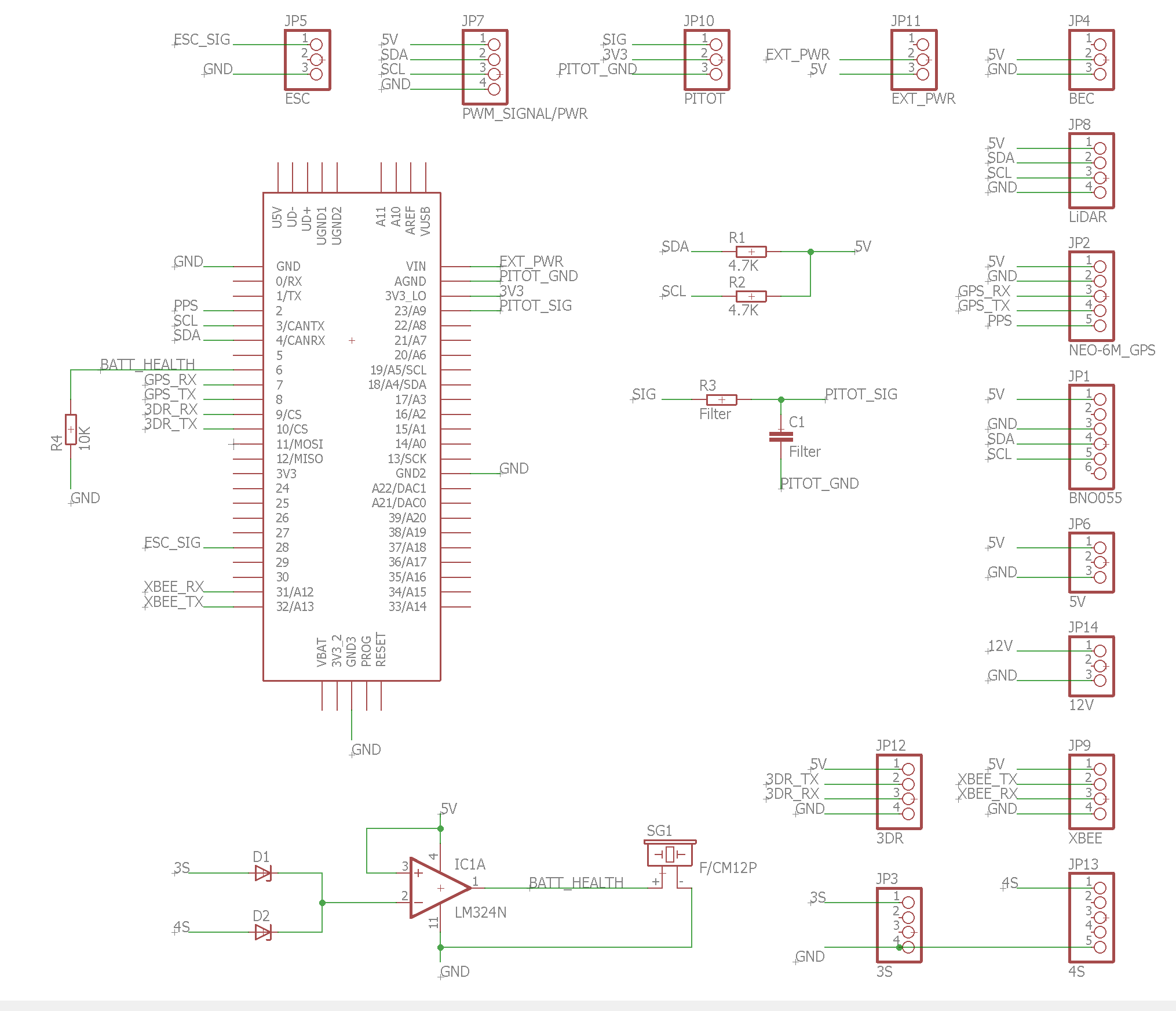
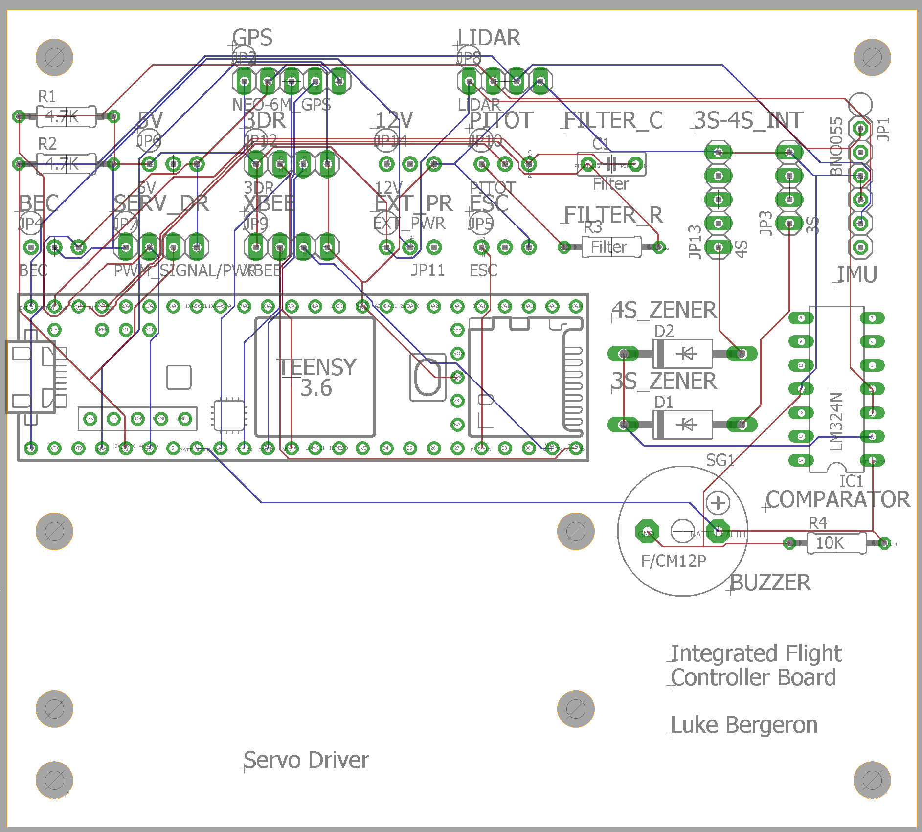
As for the new on-board PCB, here are pics of the new schematic and board layout files (Gerber files attached to the end of the post):

IFC_schematic.PNG


IFC_board.PNG


The PCB has been ordered through SeeedStudio, but haven't arrived yet. Hopefully it will work as intended once it arrives, lol.
 

Power_Broker

Active member
Update #20.)

PCB is scheduled to arrive this Wednesday!

Also, I bought an AV-to-USB adapter (here), an AV splitter cable, and an AV male-male extender. I'm going to use these to allow users to watch the FPV camera feed from both the goggles AND from my laptop screen. In order to get the AV-to-USB device to work, I had to scour the interwebs to find the right driver. If any of you want to use this device too and have a Windows machine, use the driver I've attached to this post.

Lastly, I've been tinkering around in Python to make a GUI (Graphical User Interface) for the sensor operator. So far I've been able to get live input from the USB joysticks and a few other milestones, but the code isn't done yet.
 

Attachments

  • USB_VIDBOX_FW_DRIVER.zip
    25.3 MB · Views: 0

Power_Broker

Active member
:rolleyes: Oh gosh, I just realized the zener diodes are in the reverse direction - oops. The circuit will still work as long as I solder them in the opposite way. Still haven't picked the exact diode values for the zeners, but that info should come soon.
 

Power_Broker

Active member
Update #21.)

The flight controller PCB came in a few days ago. Other than the zener diodes, I finished soldering everything onto it and will start testing all the components and connections soon. Here are the pics:

IMG_3804.JPG IMG_3805.JPG IMG_3806.JPG IMG_3807.JPG

Also, I've been working with a friend to design and make an aluminum enclosure for the on board avionics. It'll provide protection for both the electronics and battery in case of a catastrophic crash. Here is a pic of the unfinished (but soon to be finished) enclosure:

IMG_3555.JPG

Lastly, I've been making progress on the Python GUI. So far I've been able to use some demo code from around the internet to display the FPV video feed directly from the GUI on my laptop. Once the GUI is complete, I'll post the code.