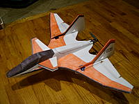
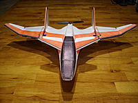
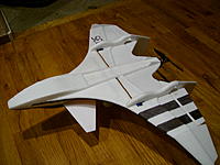
Building the F-242 Spiker
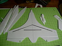
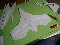
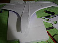
1: Get all your parts cut out. Install your wing bracing.
2: Install your KF step and top and bottom fuselage parts.
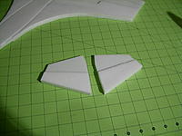
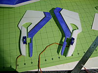
3: Assemble the winglets.
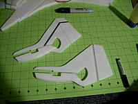
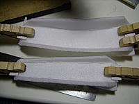
4: The tails have two bracing parts and go underneath the wing. glue one on each side of the tail. This also helps to lock the servo in place.
5: Round the leading edges of the wings and winglets.
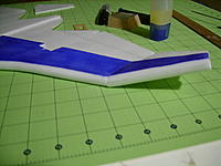
6: With everything nicely glued together, cut the angle onto the wing and winglet joining edges. Use the supplied angle guide to help get this right.
7: install the nose bracing. You want the back side to be up against the notch in the fuselage nose, do not line up the point of the nose to the front of the fuselage.
8: Using the nose bracing as a guide, trim off the excess foam from the nose of the plane.
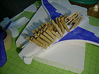
9: install the sides of the fuselage. Be sure these get well glued into place.
10: With the fuselage sides glued into place, begin to close up the fuselage of the plane, installing the top of the fuselage and bottom pieces. I start at the back with the fuslage top and work my way forward.
11: With everything all glued together hit the fuselage of the plane with some heat to help it keep the nice curve it now has. It is best you do this before you cut out the canopy, and ESC covers.
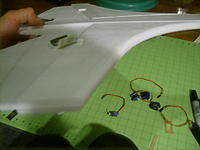
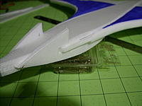
12: Install your cardboard fuselage bracing. Make sure it is glued in very strong. The brace has two cross pieces. You want the rear cross piece to be centered on the section between the canopy and ESC cutouts.
Also glue some small card board tabs onto the front and back of the canopy and ESC covers
13: Glue the servos into the notch of the tails before installing of the tails. If you want to also have rudders, be sure to cut out the notches on the upper part of the tail, indicated on the plans, for the extra servos and control horns.
14: Install your control horns.
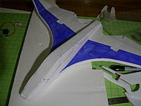
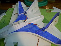
15: Slide the tails into place. If doing the optional rudders be sure you install the servos. I am using HXT900 servos for the elevons and HXT500 servos for the rudders. Also run in your wires to the fuselage.
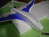
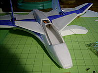
16: Install the canards onto the fuselage.
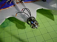
17: Install the motor mount, and poke a small hole on top of the fuse to run your wires in.
Use the supplied throw gauge to set your control surface throws. CG should be at the front of the tails, where the tails hit the leading edge of the wing.