First FC, need help on how to solder VBat for a fixed wing

Duck

Active member
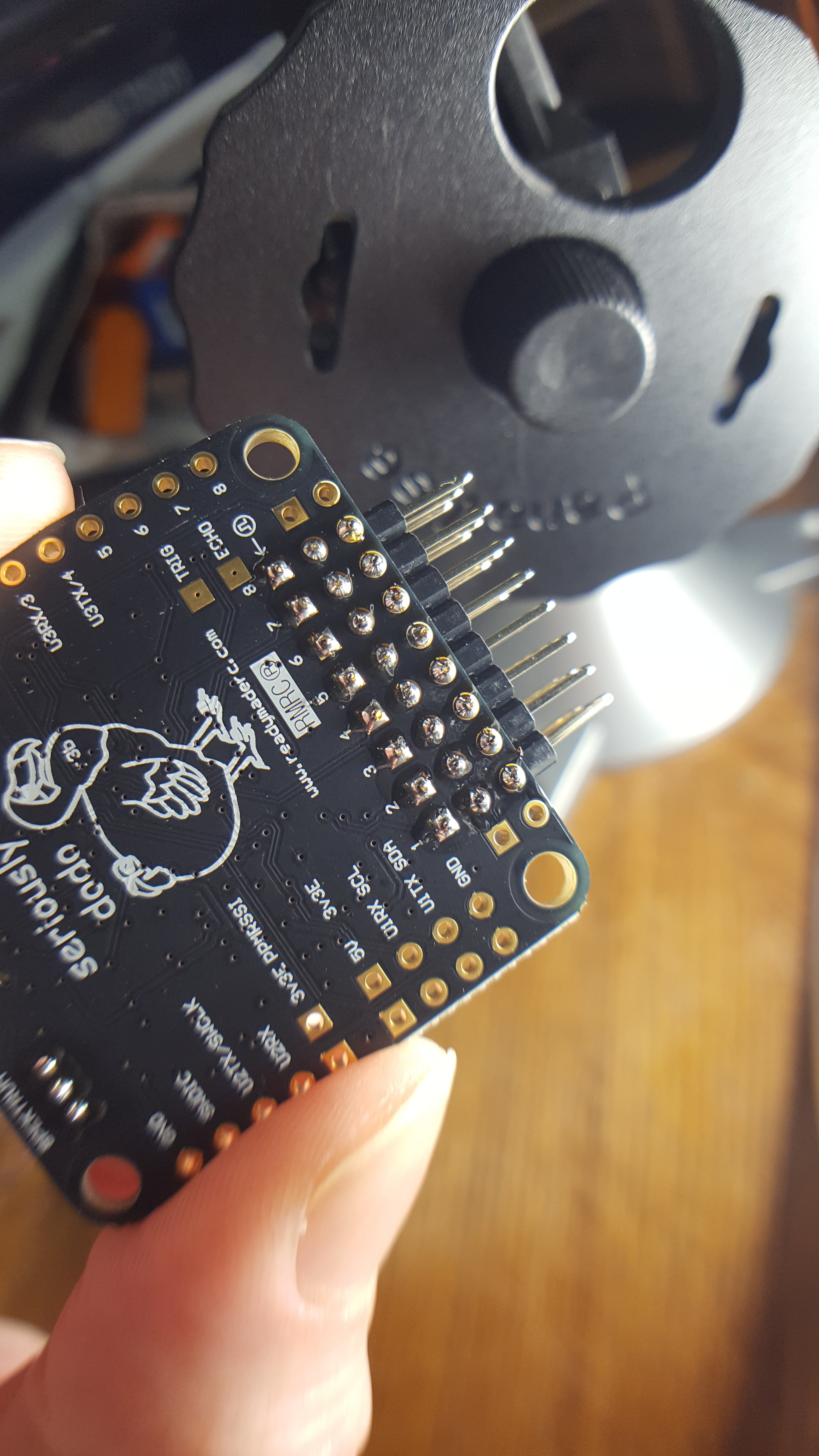
I picked up a pair of RMRC Dodp 3b boards while they were on sale with the goal of it being my first FC. Soldering the through hole connections for receiver and servos went fine. I've tested the receiver wth it connected to cleanflight.

I actually think the solder looks great for my first through-hole attempt.
20181208_212244.jpg


I had planned on soldering a JST pigtail to the vbat pins and running that to a JST tap on an xt60. This would let me move the FC around or put in an extender without resoldering. The board would power off that and also drive the servos.

The problem I ran into was that even my 20 guage JST pigtail with braided wires wont fit the VBat through-holes. I assume this is the situation where you want a flat pad instead. What are the best ways to connect these on the FC? Is my JST pigtail idea silly? How would this normally be hooked up for a wing?

I came up with a few options but each has drawbacks. I was hoping to get some sage advice to point me in the right direction.
1. Do I just need higher gauge pigtails?
2. Should I trim some braid off and make it fit?
3. Should I just use some solid copper wire that fits and splice that to the pigtail?

Board
rmrc-dodo-fc-r3a.jpg

https://www.readymaderc.com/products/details/rmrc-seriously-dodo-flight-controller-rev-3b

Thanks!
 

makattack

Winter is coming
Moderator
Mentor
I would just treat those through-hole points as pads. Tin the holes, which should end up filling the holes with solder, and with tinned wires, solder them onto the "tinned pads" on the surface. Just make sure you have a steady hand to avoid a cold solder joint and let it cool off completely before you try moving either the board or the wires. I agree with you. Very nice job on the through-hole soldering of those pins!
 

Merv

Site Moderator
Staff member
I agree with @makattack, just solder wire on as you would a pad. You could also solder on pins & solder wire to pin or attach wire with a plug.

BTW, Great looking joints, that cone like shape is what you want.
 

Duck

Active member
So, I was successful-ish doing a solder of the JST lead directly to the board treating the through hole as a pad. It wasn't nearly as clean as the other joints and will probably brake at a bad time but it should be good enough. The board powers just fine. That will have to do.

The mess is the flux, it photographs worse then it is but is worse then it should be. It will snap off in a light breeze. My only hope is that it doesn't short when it does. Is it bad to cover the whole joint in hot glue?
20181212_220849.jpg


Once I had this up and running I ran into a bit of an issue with my cleanflight configuration. I honestly don't understand the servo configuration and how that maps to pins. Powering the board via USB and connected via clean flight I can see the servos respond to the gyro and my transmitter inputs on the Servo tab. But I tried connecting the servos to pins 1-5 and they didn't respond at all. I haven't done much in cleanflight except set the FC to be a flying wing. I am reading between the lines but looking at pictures like the below I assume the servo should be on pins 3,4. Those respond in the servo tab in cleanflight.

The entire extent of cleanflight documentation:

download.png


I suspect I have failed to set something up that isn't set by default. My guess being a FC/quad newbie is that I didn't configure arming. I attempted this but with no luck.

Can somepoint point me at better documentation for cleanflight for flying wings OR the servo tab in cleanflight OR how to determine the mapping of servos to pins based on board (RMRC Dodo V3) OR cleanflight flying wing setup from scratch OR a magic crystal ball. I'll take any of the above. As a software engineer, I am used to bad software documentation but the cleanflight docs are really bad to the point of useless in this area. I really hope I am just missing the 'real' documentation somewhere. I suspect this isn't the case though.
 

ElectriSean

Eternal Student
Mentor
Pins 3 & 4 are what you're after. You should get servo movement even without arming, but you will probably have to connect battery power, I doubt those pins are powered by USB.

Should also note that the BEC on board the FC probably isn't up to the task of powering servos, it is fairly small - designed to power receivers and GPS etc. I'd recommend an external BEC, if your ESC has one built in use that.
 

Duck

Active member
@ElectriSean Thanks! I'll try running a single 5g servo and see if I see a response. This should rule out any issues powering from USB and any issues with the FC BEC because it should be able to power a single tiny servo. The spec sheet claims 1A on the BEC. I had been testing 2x 9g servos so exceeding 1A is possible I guess (?).

For substituting the BEC from the FC, I had a couple of questions. I was unable to find a good resource on alternate configurations here without a PDB with a much higher amp limit on the BEC. I bought a PDB just in case but ideally it wouldn't be needed.

For powering servos, can someone help point me towards answers for:
* What is the amp draw from normal FT servos? Specifically for 5g and 9g servos from the power pack. I have yet to find a spec sheet that can help me here. I've been testing with 'power up' brand servos' but a range of amp draw would be super helpful when reasoning about this.
* What is the best wiring for a wing with a single ESC with BEC with an FC that takes VBAT? It seems like it is recommended to remove the + lead for driving ESC for the FC control signal. But that means servos run from the FC BEC. Can someone point at an alternate wiring for driving multiple servos from the single ESC BEC?
* How do I power servos from the ESC BEC and ignore the + line coming from the FC which is from the FC BEC? Omit that lead on the FC side and connect it on the servo side? It seems like this is a LOT of custom wiring.

I _do_ have a huge pile of FF/MM/FM header leads from a project years ago (thanks sparkfun!) so removing a single wire from a 3 wire connector for servo/ESC is possible. I just connect the pins needed and leave the rest off. This gives me 8" of extra wire with a slightly finicky connector but it has worked in the past on dual ESC FT planes to remove one + line from the receiver. I have no idea how everyone else does this. Those connectors looks impossible to build by hand.
 

ElectriSean

Eternal Student
Mentor
For powering servos, can someone help point me towards answers for:
* What is the amp draw from normal FT servos? Specifically for 5g and 9g servos from the power pack. I have yet to find a spec sheet that can help me here. I've been testing with 'power up' brand servos' but a range of amp draw would be super helpful when reasoning about this.

I'm not sure, a lot of manufacturers only publish torque and speed specs. 2A should be more than enough. 1A may even work, but if you push it too hard you may overload the BEC and end up browning out your receiver and FC.

* What is the best wiring for a wing with a single ESC with BEC with an FC that takes VBAT? It seems like it is recommended to remove the + lead for driving ESC for the FC control signal. But that means servos run from the FC BEC. Can someone point at an alternate wiring for driving multiple servos from the single ESC BEC?
* How do I power servos from the ESC BEC and ignore the + line coming from the FC which is from the FC BEC? Omit that lead on the FC side and connect it on the servo side? It seems like this is a LOT of custom wiring.

This is a (terrible) drawing of how I have done my wing. Intersections with a dot are connections, where the lines curve over each other is not connected.
wingfc.gif


Unless you go for a FC designed for a wing (Matek makes a few) you are going to have to do custom wiring, it's just part of the game. You've already got the Lipo/ESC side of things done, so it's just the servo power connections. When I did mine, I soldered and shrink tubed the wire splices and hid them under the FC.

20180629_214802sm.jpg
 

Duck

Active member
Thanks for the diagram. I guess wiring something like that is my next step. It was about what I expected but knowing other people do that gives me a lot more confidence I am not going down the wrong rabbit hole.

Powering from the VBAT brings the FC up but still no movement on a 5g servo on either pins 3 or 4. This confirms that it wasn't just that I was attempting 2x 9g servos that were too much for the 1A BEC.

Can someone confirm my understanding of the motors tab? If I see 'Servos' 1-8 moving, that means it _should_ be attempting to really move those servos. It isn't just a simulation of what should happen. Is that right?

I did just notice on the motors tab that servos 4-5 are moving when I change the orientation of the board. Not 3-4. That said, I tried the 5g servo in each of the pins and saw no difference. It never moved.
 

ElectriSean

Eternal Student
Mentor
I haven't actually played with Cleanflight for over 2 years, and that was just with multirotors so I'm not exactly clear on how servos behave in the GUI. My wing runs inav, which has recently gotten some massive improvements on fixed wing stuff.

When you power up the FC with everything connected, part of the boot up should be centering the servos. Once you're booted you should have control of the elevons with your Tx. If nothing is happening, I suspect the servos aren't getting proper power. Do you have a meter to verify? Are you certain the servos are plugged in properly?
 

makattack

Winter is coming
Moderator
Mentor
That brings up a good point. Why use cleanflight vs iNav? I think there are more people using iNav for fixed wing purposes than cleanflight, so there may be better chance of success with inav instead. The only servo application I have had experience with *flight (in my case, betaflight) is a tricopter setup on a SPRacingF3 board. I setup my servo on BF3.3.3 as such:

Code:
resource SERVO 1 A02
servo 5 1125 1905 1500 100 -1
smix reverse 5 2 r

I believe cf is now based off bf, so the resource mapping and servo setup should look similar, but I would check the documentation.
 

Duck

Active member
@makattack I'll expose my limited FC knowledge here. I actually have no idea if the different FC software is cross compatible generally or specifically with my board. I know the board is old and so likely recommends clean-flight as it was a good choice at the time. I use betaflight for my Vortex. I've never tried to connect with the other or flash at the risk of unintended side effects or just bricking the board. I assumed using the recommended solution would be the most likely to produce a working result. If that needed improvements I could look at alternatives. Really the only reason to choose this board was it was 10$ and I happened to be buying from RMRC anyway. I figured worst case I would ruin it while soldering and be only 10$ in the hole.

I got curious from those commands you listed. The middle looks like configuring the servo channel itself. The last is remapping for yaw (? tricopter, right?). But the first, I couldn't tell what it did. Looking at the betaflight docs (yay docs!) I saw a list `resource command` so I gave it a try:

# resource list
IO
A00: FREE
A01: FREE
A02: FREE
A03: FREE
A04: ADC_BATT
A05: ADC_CURR
A06: MOTOR 1
A07: FREE
A08: FREE
A09: SERIAL_TX 1
A10: SERIAL_RX 1
A11: FREE
A12: FREE
A13: FREE
A14: FREE
A15: FREE
B00: FREE
B01: FREE
B02: ADC_RSSI
B03: LED 1
B04: FREE
B05: FREE
B06: I2C_SCL 1
B07: I2C_SDA 1
B08: FREE
B09: FREE
B10: FREE
B11: SERIAL_RX 3
B12: FLASH_CS
B13: SPI_SCK 2
B14: SPI_MISO 2
B15: SPI_MOSI 2
C13: MPU_EXTI
C14: FREE
C15: BEEPER
F00: FREE
F01: FREE
F03: FREE
F04: FREE

What I was expecting was to have the left column (pins on main chip?) map to something like 'Servo 3' / 'Servo 4'. I see `Motor` on there but two-three pins down (assuming motor is S1 and somewhere in S3-5 are servos) are TX and RX. Given that TX and RX are asymmetrical and servos are generally not I can guess those are NOT the servos. What should the resource map look like for servos? How might I determine which pins those should be assigned to for the RMRC Dodo v3? I had to learn to read spec sheets in the past but I am not finding even that cryptic level of documentation here.
 

ElectriSean

Eternal Student
Mentor
Your board is an F3 so you can definitely run Betaflight or Cleanflight, iNav is also supported on that board. If you have set up the mixer as a flying wing, the servo resources should be assigned for you.
 

Duck

Active member
So, interesting result. Just doing diff or dump in the CLI shows that the servos claim to be mapped to no pins. That can't be good.
 

Duck

Active member
My diff looks like this:

CLI # diff
# Cleanflight / RMDO (RMDO) 2.4.0 Jul 16 2018 / 18:15:39 (73a6edeca) MSP API: 1.39

board_name RMDO
manufacturer_id
name SlowFlyingDuck
mixer FLYING_WING

map TAER1234
aux 0 0 0 1300 2100 0
aux 1 1 1 1300 1700 0
aux 2 2 1 1700 2100 0
set serialrx_provider = SPEK2048
profile 0

set dterm_setpoint_weight = 0
set throttle_boost = 0
rateprofile 0

From dump I get

...
resource MOTOR 1 A06
resource MOTOR 2 A07
resource MOTOR 3 A11 <<< Not one of these
resource MOTOR 4 A12 <<<
resource MOTOR 5 B08 <<<
resource MOTOR 6 B09
resource MOTOR 7 A02
resource MOTOR 8 A03
resource SERVO 1 NONE
resource SERVO 2 NONE
resource SERVO 3 NONE <<< I assume I want one of these
resource SERVO 4 NONE <<<
resource SERVO 5 NONE <<<
resource SERVO 6 NONE
resource SERVO 7 NONE
resource SERVO 8 NONE
...

Am I barking up the wrong tree?
 

ElectriSean

Eternal Student
Mentor
Looks like the right tree to me... I would try assigning servos 3 & 4 to motors 3 & 4 resources...

resource MOTOR 3 none
resource SERVO 3 A11
etc.

make sure you save
 

makattack

Winter is coming
Moderator
Mentor
If you're looking to remap resources, I would look at the docs and source code for whatever software you prefer, but as @ElectriSean states, some software may remap for you based on the vehicle type mix.

First look at the doc for the board, specific to the software:

https://github.com/cleanflight/cleanflight/blob/master/docs/boards/Board - RMDO.md

Then look at the code to see the pin mappings:

https://github.com/cleanflight/cleanflight/blob/master/src/main/target/SPRACINGF3/target.c

Based on the above docs, I would agree that A11 and A12 are appropriate to remap to servos 3 and 4 with your board.
 
Last edited:

Duck

Active member
If you're looking to remap resources, I would look at the docs and source code for whatever software you prefer, but as @ElectriSean states, some software may remap for you based on the vehicle type mix.

First look at the doc for the board, specific to the software:

https://github.com/cleanflight/cleanflight/blob/master/docs/boards/Board - RMDO.md

Then look at the code to see the pin mappings:

https://github.com/cleanflight/cleanflight/blob/master/src/main/target/SPRACINGF3/target.c

Based on the above docs, I would agree that A11 and A12 are appropriate to remap to servos 3 and 4 with your board.

@makattack, I found that pair of files but not knowing the conventions it wasn't obvious how to map the values to the pins shown when I do `resource list`. Are you just counting down in the motor list, then stripping the P prefix off the third column?

https://github.com/cleanflight/cleanflight/blob/master/src/main/target/SPRACINGF3/target.c#L42-L43

I had missed that 'PA11' has the suffix 'A11' which is in the resource list. Is there anything else going on in this list? What do the first two columns and the comments tell you?

I'll try remapping, then powering from my ESC using the diagram from @ElectriSean and hope for the best. Thanks everyone!
 

makattack

Winter is coming
Moderator
Mentor
Yeah, unfortunately, reading docs and source code sometimes is lacking extra information. The PA11 notation you see in that C/C++ macro is referencing a standard STM32 library define that references the pins (hence, the P, I think) on the processor/IO system. So, as you guessed, if you remove the P, the Cleanflight code references that as "A11" in their configuration.

Software is basically just a remapping of stuff... hardware -> software... or in this case, hardware -> software -> software... ;)

Yeah, basically, if you remap the analog pins 11, 12 (hence the PA?) you'll likely get the PWM output needed to drive the servos.
 

Duck

Active member
Success! There was one more bonus step. Cleanflight (and betaflight?) refer to servo 3-4 or 4-5 everywhere in the UI but in the CLI, when assigning resources, you need to assign Servo 1-2 to pins 11,12. Because that is intuitive :) I am also still not clear why these were not assigned by default as I've seen multiple suggestions they should be.

Somehow my receiver settings got reset but after that I have a servo that responds* to both aileron/elevator control from the receiver and the gyro. *Not sure if the response is the right direction or not but this is 90% there. The diagram from @ElectriSean worked great. I only wired a single servo because I could do that without soldering but now that I have it working I can splice an extra +/- lead to power the second servo.

Next step after that is choosing a wing to install it on but that should be easy enough. Either my FT Spear, a new wide body FT mini arrow (I cracked the last one in half) or my never maidened FT goblin. Choices!

Thanks everyone for the assistance! Your help and encouragement was great. I promise to post on either maiden or epic crash.