Flying Laser Tag

What FT plane would be best to carry the prototype (150g?)


  • Total voters
    13
  • Poll closed .

Duck

Active member
I gave a few teasers in another thread but I wanted to start a thread to share progress on my flying laser tag gun. I wanted to share progress and collect a few suggestions along the way.

Previous Thread:
https://forum.flitetest.com/index.php?threads/laser-tag-combat-community-suggestions.37994/

Blog Post:
https://executedata.blogspot.com/2020/03/flying-laser-tag-gun.html

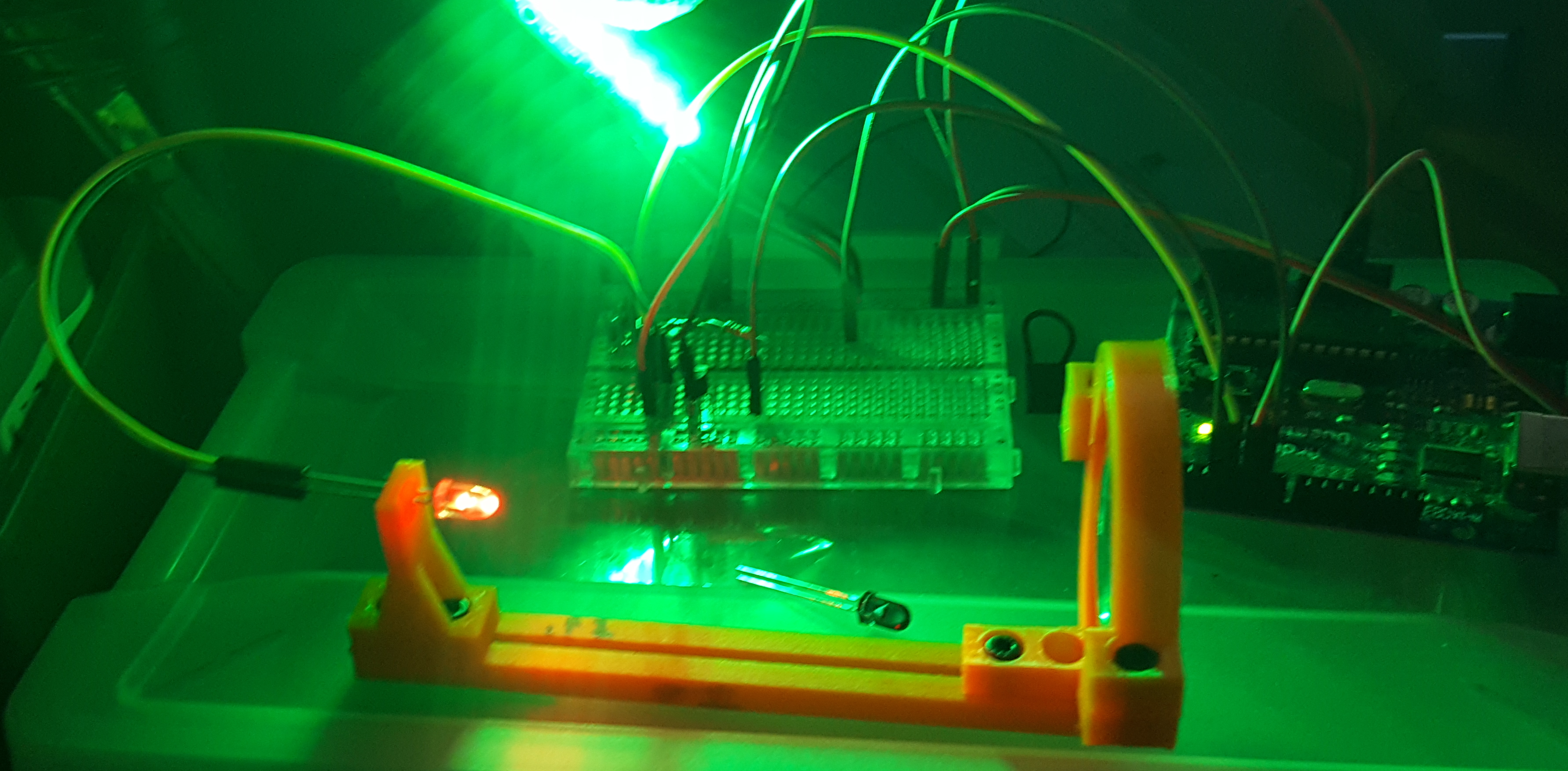
To justify forking the thread, here is an exclusive never before seen shot of the IR TX while I was testing the focus in the dark with a visible light LED.
1583207628714.png


All the bits are up on github if you want more:
https://github.com/afaucher/Tagger
 

Duck

Active member
The first question I have is what plane would be best to try and attach the prototype to. A couple of things to keep in mind:
  1. I fly almost exclusively on lumpy grass
  2. Any plane I don't own means testing waits a few months :p
  3. The first version will be quite heavy. My rough guess is 150g. I haven't figured out a power system that doesn't require an extra battery which is most of it. I also have 2x LED strips, a 2"glass lens because I can't find a good plastic one and a fair number of 3d printed parts.
  4. The FPV camera MUST see the wings so you can see your own LEDs. An already tail heavy plane is out.
  5. I have no idea if the IR TX will work through the prop.
  6. The IR RX has to be mounted on top of the aircraft and is physically on top of the arduino so it is quite big.
I started a poll to see if anyone has additional considerations or recommendations. I am happy to build a new plane but it will take a bit given how many projects I am juggling.
 
Last edited:

mayan

Legendary member
I say go with the Spitfire. It's a stable design and I am sure you can find a way to put all the electronics you need inside.
 

Captain Video

Well-known member
Great rig. The spitfire sounds like a great idea. I'd like to put in my go to plane like my high wing Apprentice S 1.5. If you need a test plane I volunteer. I would put the other in my Strix Alutus racing wing plenty of space in the fuse even with the FPV. I would let my 21 yr old sons try to slice me up in a battle. Slow vs fast.
 

FoamyDM

Building Fool-Flying Noob
Moderator
any C-pack plane should be able to hold it and fly well. I personally like my explorer with the longer nose.
 

Duck

Active member
Great rig. The spitfire sounds like a great idea. I'd like to put in my go to plane like my high wing Apprentice S 1.5. If you need a test plane I volunteer. I would put the other in my Strix Alutus racing wing plenty of space in the fuse even with the FPV. I would let my 21 yr old sons try to slice me up in a battle. Slow vs fast.

I have a Strix Alatus. The box itself isn't likely to fit in the fuse and there will be a large 2" lens that would need to mount externally. You also couldn't see your own health indicators as FPV on the Alatus is right in the nose.

In terms of volunteers, I won't make more then a few myself. All the plans will be online if someone wants to make one or improve it.
 

Duck

Active member
any C-pack plane should be able to hold it and fly well. I personally like my explorer with the longer nose.

If I can get my bronco flying it would be my first choice. It has the same body and lots of space for mounting. I cracked one of the spars on my last failed maiden so it won't be flying right away.
 

evranch

Well-known member
Milestag! Man that takes me back. Like, a decade or more back.

A good friend and I built a pair of guns back in our trade school days, with the at-the-time advanced PIC microcontrollers. I carved me a beautiful P90 out of a chunk of wood and he made an MP5. We used reed switches to build removable magazines that you had to pull out and invert to reload. My P90 was always a little fussy as it has an unusual mag.

This was in the pre-3D printer days, so mounting lenses was a lot of work and we had the same issue with being unable to find good lenses. Nice that you can buy decent glass ones on Amazon these days. I love the 3D printed mount, so much easier than what we had to deal with.

I still have a box of IR receivers and high powered LEDs in my parts drawer somewhere, we bought enough to build 10 guns but with the big terrorism scare at the time, it was hard to find good places to play and other players who were willing to build their own guns. We had great plans to build grenades, ammo boxes, captureable spawn points but it fizzled out.

Always thought someone should port the system from those crappy PICs to Arduino. Looks like it will be a lot of fun on airplanes. You might be able to send the health data to the OSD as telemetry data, depending on what OSD you're running or if you're using one at all.

Do NOT use the Spear, it has serious yaw stability issues. Not a great FPV/aiming platform. Bronco is probably your best bet of the platforms you named.
 

Duck

Active member
Milestag! Man that takes me back. Like, a decade or more back.

A good friend and I built a pair of guns back in our trade school days, with the at-the-time advanced PIC microcontrollers. I carved me a beautiful P90 out of a chunk of wood and he made an MP5. We used reed switches to build removable magazines that you had to pull out and invert to reload. My P90 was always a little fussy as it has an unusual mag.

This was in the pre-3D printer days, so mounting lenses was a lot of work and we had the same issue with being unable to find good lenses. Nice that you can buy decent glass ones on Amazon these days. I love the 3D printed mount, so much easier than what we had to deal with.

I still have a box of IR receivers and high powered LEDs in my parts drawer somewhere, we bought enough to build 10 guns but with the big terrorism scare at the time, it was hard to find good places to play and other players who were willing to build their own guns. We had great plans to build grenades, ammo boxes, captureable spawn points but it fizzled out.

Always thought someone should port the system from those crappy PICs to Arduino. Looks like it will be a lot of fun on airplanes. You might be able to send the health data to the OSD as telemetry data, depending on what OSD you're running or if you're using one at all.

Do NOT use the Spear, it has serious yaw stability issues. Not a great FPV/aiming platform. Bronco is probably your best bet of the platforms you named.

You could almost drop the code right into a gun and play with it as-is. I added a manual trigger for testing. The only difference is that for planes it is designed to hold the trigger via a TX switch for continuous fire as there isn't a traditional trigger where you can pull. That might actually be just fine if you don't mind being a little overpowered :) The protocol is not Milestag though. It uses the same protocol as the Phoenix LTX guns.

I based the lens setup off of one I saw on thingiverse:
1583340438396.png
https://www.thingiverse.com/thing:454862

But you can see the compatible guns here:
1583340326953.png
https://www.amazon.com/dp/B00DW1JT2O/?tag=lstir-20
 

Duck

Active member
It looks like the FT Bronco is coming out the winner. I guess I'll break out my hot glue gun and start putting it back together. In the meantime I got a few parts in the mail!

20200306_095724.jpg


I emailed Jim from the now closed lasertagparts.com and was able to order his custom PCB for the IR receiver domes. He was kind enough to also include some of his remaining plastic domes (left) which fit perfectly over his board. My own PCB includes the option to either build the dome directly on the board or connect one via a cable. This should let me test out that method.

I also bought a 40mm acrylic dome off Amazon that should also fit (right). It is more expensive, thinner material, wider and not as tall. Jim said he didn't have more domes so that is my backup solution that I can attach directly to the Arduino case. If anyone spots a better solution, please speak up! I really don't want a $9 plastic dome to be my best option. The ideal dome would block everything but IR. These exist for a few applications, laser tag being one of them, but I haven't be able to find any that are not $40 a piece and also too large.

While waiting for these I also started my custom Arduino case that will be needed to keep everything together while mounted in a plane. In the picture you can see the bottom plate where I was just testing the screw hole spacing. I'll build up the walls and make cutouts for the different connectors and the IR dome next.
 

Duck

Active member
The build is progressing nicely. I have rev2 of the case ready as well and everything mostly fits.

20200309_192230.jpg 20200309_192216.jpg 20200309_192138.jpg

A couple of small fit issues to address both in the PCB and the case:
  • The LED header is right above the USB header on the Arduino and the pins may touch the metal case. This is bad! An Arduino with a smaller USB header would be fine.
  • The capacitor is too close to the dome and the nice domes from LaserTagParts.com don't go all the way down to the PCB because it hits the edge of the capacitor.
  • The dip switches are also too close to the dome.
  • The case is really snug against both the power and USB headers. I shaved a millimeter off in rev3.
  • The hole in the case for the cap is offset. It 'fits' but is really ackward and a bad positioning when soldering would mean the case wouldn't fit.
  • The case is a bit flimsy. It is only 2mm thick and the corners stick out. I made them wrap around a tiny bit more in rev3.
I should have enough to actually determine total weight of the whole rig very shortly.
 

evranch

Well-known member
Nice to see a project coming together! Pretty easy to relocate C1 there, if that's a main problem you are doing pretty well.

I have to say it's a little funny to have designed a hole in your case for a transistor that stands proud, assuming that's not an optical component as well. I'm assuming it's the IR LED driver. You might just have to make your case 1mm taller, which would also solve the dip switches problem :) Why not just bend the leads and mount it flush, or go with a SMT transistor?
 

Duck

Active member
Nice to see a project coming together! Pretty easy to relocate C1 there, if that's a main problem you are doing pretty well.

I have to say it's a little funny to have designed a hole in your case for a transistor that stands proud, assuming that's not an optical component as well. I'm assuming it's the IR LED driver. You might just have to make your case 1mm taller, which would also solve the dip switches problem :) Why not just bend the leads and mount it flush, or go with a SMT transistor?

The pcb did not consider the case at all. My fault entirely :) That is a transistor. I may be able to bend it once the spares arrive. Breaking it now would prevent me testing for a week. Ill plug the hole if I can bend it. I don't want to make the case taller if possible. It would be 2mm. It needs to sit on top of your plane so size matters. SMT is out until I learn to solder them. 😁
 

Duck

Active member
The pcb did not consider the case at all. My fault entirely :) That is a transistor. I may be able to bend it once the spares arrive. Breaking it now would prevent me testing for a week. Ill plug the hole if I can bend it. I don't want to make the case taller if possible. It would be 2mm. It needs to sit on top of your plane so size matters. SMT is out until I learn to solder them. 😁

The dip switch actually hits the dome, not the case. The smaller domes sit in the hole and stick out below 3mm-ish. I will just relocate the switch if I make more boards. It isnt required to use the board so I wont attach it for now. The only goal is to let you change settings in the field.
 

evranch

Well-known member
Yes, more risk of breaking it if you bend the leads after mounting. Instead it's pretty easy to use your needlenose to put a 90 degree bend in the leads and then solder the next one flush.

A lot of people are intimidated by SMT but you don't have to use a submicro transistor on tiny pads. There are lots of reasonable-sized and powerful MOSFETs out there for almost no money, think of the ones you find in an ESC. (you might even have some for free in a ruined ESC)
Since the IR tagger protocol is really slow by transistor standards, you could even use a big slow power MOSFET with a 30A rating and it would work fine.

This is an easy SMT package to solder by hand:
a7842896-17-HobbyPower%2030A%20mosfet.jpg


I see what you mean with the dome, I was thinking lifting the case lid higher would lift the dome as well but if the case is what's retaining it, maybe not.
 

Duck

Active member
Yes, more risk of breaking it if you bend the leads after mounting. Instead it's pretty easy to use your needlenose to put a 90 degree bend in the leads and then solder the next one flush.

A lot of people are intimidated by SMT but you don't have to use a submicro transistor on tiny pads. There are lots of reasonable-sized and powerful MOSFETs out there for almost no money, think of the ones you find in an ESC. (you might even have some for free in a ruined ESC)
Since the IR tagger protocol is really slow by transistor standards, you could even use a big slow power MOSFET with a 30A rating and it would work fine.

This is an easy SMT package to solder by hand:
a7842896-17-HobbyPower%2030A%20mosfet.jpg


I see what you mean with the dome, I was thinking lifting the case lid higher would lift the dome as well but if the case is what's retaining it, maybe not.

I just discovered a whole bag of extra transistors and a whole bag of mosfets I had no idea I had. I had added a discrete semiconductor kit to my cart on sparkfun awhile back to get free shipping and apparently it just paid for itself again. They are all quite a bit smaller then the one I am using. I may not even have to bend them down to fit.

This is what is on the board: https://www.sparkfun.com/products/13689 - Rated to 800mA
I have a bag of these: https://www.sparkfun.com/products/521 - Rated to 200mA

I run the LED at 100mA and its peak rating is 200mA so I can likely just swap them. The other ones also have narrower pins so I will have to do some pin bending anyways. Apparently I have 25 of them so I can afford to break one :)

I also printed rev3 of the case last night and the fit is much better.
 

evranch

Well-known member
Nothing wrong with the classic 2N3904, probably the most common semiconductor in the world. Perfect for your application.

You should be able to drop it in no problem, they have similar beta values and if you are driving it with what looks like a 1k base resistor either transistor will be well in to saturation anyways.

The one serious reason I've considered buying a 3d printer is to print cases, it looks so convenient to be able to tailor your case to your boards and premade cases are getting stupidly priced these days.
 

Duck

Active member
Nothing wrong with the classic 2N3904, probably the most common semiconductor in the world. Perfect for your application.

You should be able to drop it in no problem, they have similar beta values and if you are driving it with what looks like a 1k base resistor either transistor will be well in to saturation anyways.

The one serious reason I've considered buying a 3d printer is to print cases, it looks so convenient to be able to tailor your case to your boards and premade cases are getting stupidly priced these days.

A stock case and a Dremel would likely work just as well for most use cases. I wouldn't call the process 'convenient' so far. Not hard by any means but lots of fiddling around. I pulled another case off thingiverse for reference and dropped it into Rhino alongside a PNG of my PCB. That at least got me the hole positions right on the first try and I just added/removed a mm or two on each revision to dial it in. The biggest bonus for me is I can say 'make 3 more' fairly easily and get near exact replicas. You can't do that easily if you just modify existing cases.
 

evranch

Well-known member
The biggest bonus for me is I can say 'make 3 more' fairly easily

Exactly, over the next couple years I have around 100 telemetry devices to build and roll out on my irrigation district. As such I practically have to design the device around the case to get a readily available, affordable case that works for my needs.

I have considered that buying a small 3d printer to fabricate custom cases might be cheaper and easier than buying the cases themselves and modifying them to add the antenna mounts, battery boxes etc. If I could make boxes with printed posts that readily available ESP32 boards can clip in to, it would save me a ton of time.