Hello,
I am relatively new to flying wing design and I am trying to understand the design process. In order to choose an airfoil, I created a small MATLAB script working with XFoil to select one between some of the NACA5 (reflex) foils. According to my requirements (very large thickness, specific Cl range, optimum Cl/Cd, positive Cm) I ended up choosing the NACA54129. I know that XFoil is a 2D analysis program and that results can be radically different when switching to 3D but I first want to understand the 2D design process. Now that I have an airfoil that can generate enough lift, I need to guarantee longitudinal stability.
From what I learned, if Cm is positive and CG is ahead of the AC then the distance between the CG and the AC must accomplish the following: equilibrium between the pitching moment at AC and the lift moment arm (xAC-xCG)*L during cruise (trim), and the desired static stability margin is satisfied (the smaller the distance, the less stable it is and vice-versa). My 2 variables being the cruise AoA and the CG coordinate (that can be adjusted with the electronics placement), I have enough freedom to solve for a specific static margin, and moment balance at trim. If Cm is constant, as it is the case at the AC, it seems like a pretty straightforward calculation.
However the XFoil generated Cm is taken at 0.25 chord, which is not always the AC, and in my case Cm is in fact not constant. I tried finding the AC by finding the "most" constant Cm by computing in MATLAB Cm=Cm_0.25+x*Cl for different values of x, but this ended up not being very conclusive. From the results that XFoil gives me, how would I go about placing the CG in order to satisfy static stability? Should I work with the Cm results at 0.25 chord or should I find the AC and work with Cmac? Should I design the flying wing with a radically different approach (maybe not using XFoil)? Also, my analysis uses Re=300,000 and 17m/s, Ncrit=9.
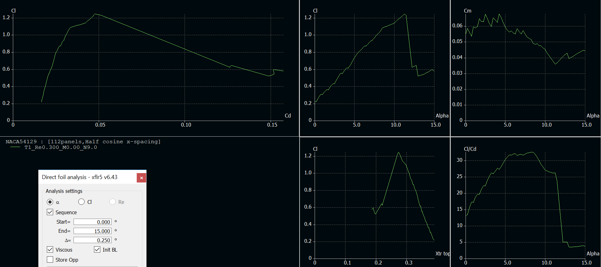
Linked is the NACA54129 airfoil, and XFoil polar plots
Thanks,
Matt LC
I am relatively new to flying wing design and I am trying to understand the design process. In order to choose an airfoil, I created a small MATLAB script working with XFoil to select one between some of the NACA5 (reflex) foils. According to my requirements (very large thickness, specific Cl range, optimum Cl/Cd, positive Cm) I ended up choosing the NACA54129. I know that XFoil is a 2D analysis program and that results can be radically different when switching to 3D but I first want to understand the 2D design process. Now that I have an airfoil that can generate enough lift, I need to guarantee longitudinal stability.
From what I learned, if Cm is positive and CG is ahead of the AC then the distance between the CG and the AC must accomplish the following: equilibrium between the pitching moment at AC and the lift moment arm (xAC-xCG)*L during cruise (trim), and the desired static stability margin is satisfied (the smaller the distance, the less stable it is and vice-versa). My 2 variables being the cruise AoA and the CG coordinate (that can be adjusted with the electronics placement), I have enough freedom to solve for a specific static margin, and moment balance at trim. If Cm is constant, as it is the case at the AC, it seems like a pretty straightforward calculation.
However the XFoil generated Cm is taken at 0.25 chord, which is not always the AC, and in my case Cm is in fact not constant. I tried finding the AC by finding the "most" constant Cm by computing in MATLAB Cm=Cm_0.25+x*Cl for different values of x, but this ended up not being very conclusive. From the results that XFoil gives me, how would I go about placing the CG in order to satisfy static stability? Should I work with the Cm results at 0.25 chord or should I find the AC and work with Cmac? Should I design the flying wing with a radically different approach (maybe not using XFoil)? Also, my analysis uses Re=300,000 and 17m/s, Ncrit=9.
Linked is the NACA54129 airfoil, and XFoil polar plots
Thanks,
Matt LC