Horseman3381
Well-known member
Foamboard NASA Shuttle Carrier 747
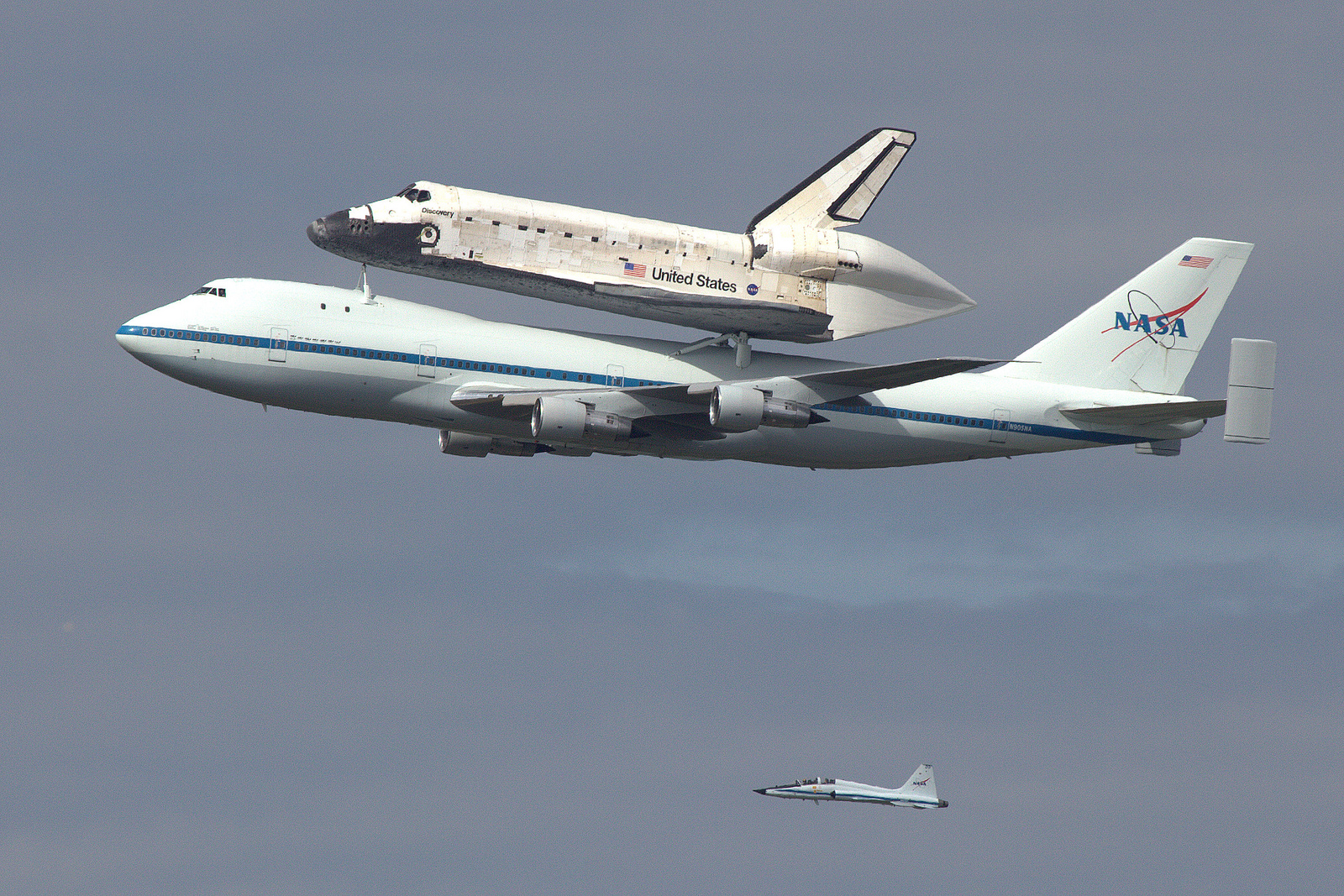
The NASA Shuttle Carrier Aircraft are Boeing 747-100 that were used to ferry the space shuttles from their landing site to the launch facility at Kennedy Space Center. The first of these aircraft was built in 1976 from a surplus 747 purchased from American Airlines. The Second was built in 1990 from a Surplus 747 from Japan Airlines.
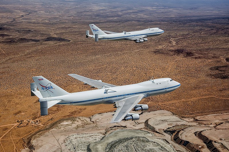
I have been planning to build this plane for over a year now and finally got around to starting it earlier this year. My intent for the project is to build the 747 to take off carrying the space shuttle. Once the plane gets up to altitude the shuttle will be able to separate and be flown back to ground.
I wanted to build the plane as large as I could and still fit it in my car. This puts the Fuselage at 8’-9” long. With that determined here are specifications:
747 Specifications:
Space Shuttle Specifications:
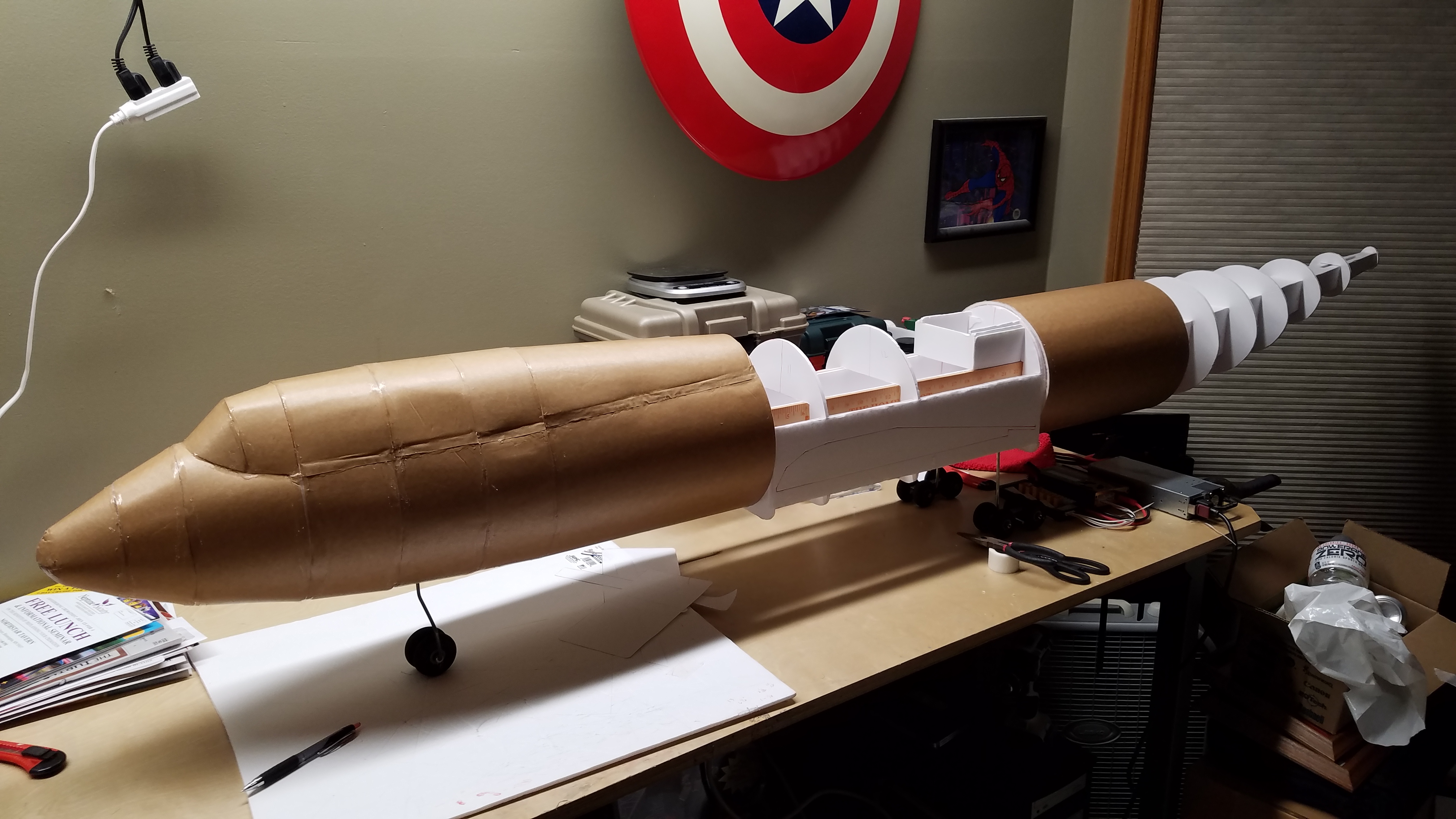
The 747 fuselage is built using a center foamboard box spar with formers. These are wrapped in foarmbard sheets. Wooden yard sticks run the length of the fuselage attached to the box spar to structurally reinforcing in the fuselage. Paint sticks are used as the spar in the vertical and horizontal stabilizers.
I investigated several options for attaching the wings to the fuselage. With the swept wings of the 747 and the dihedral they have, it is not possible to have a removable spar that runs between them. I investigated using an aluminum tube frame, but in order to get tubing in a size/thickness that would have worked would was rather expensive.
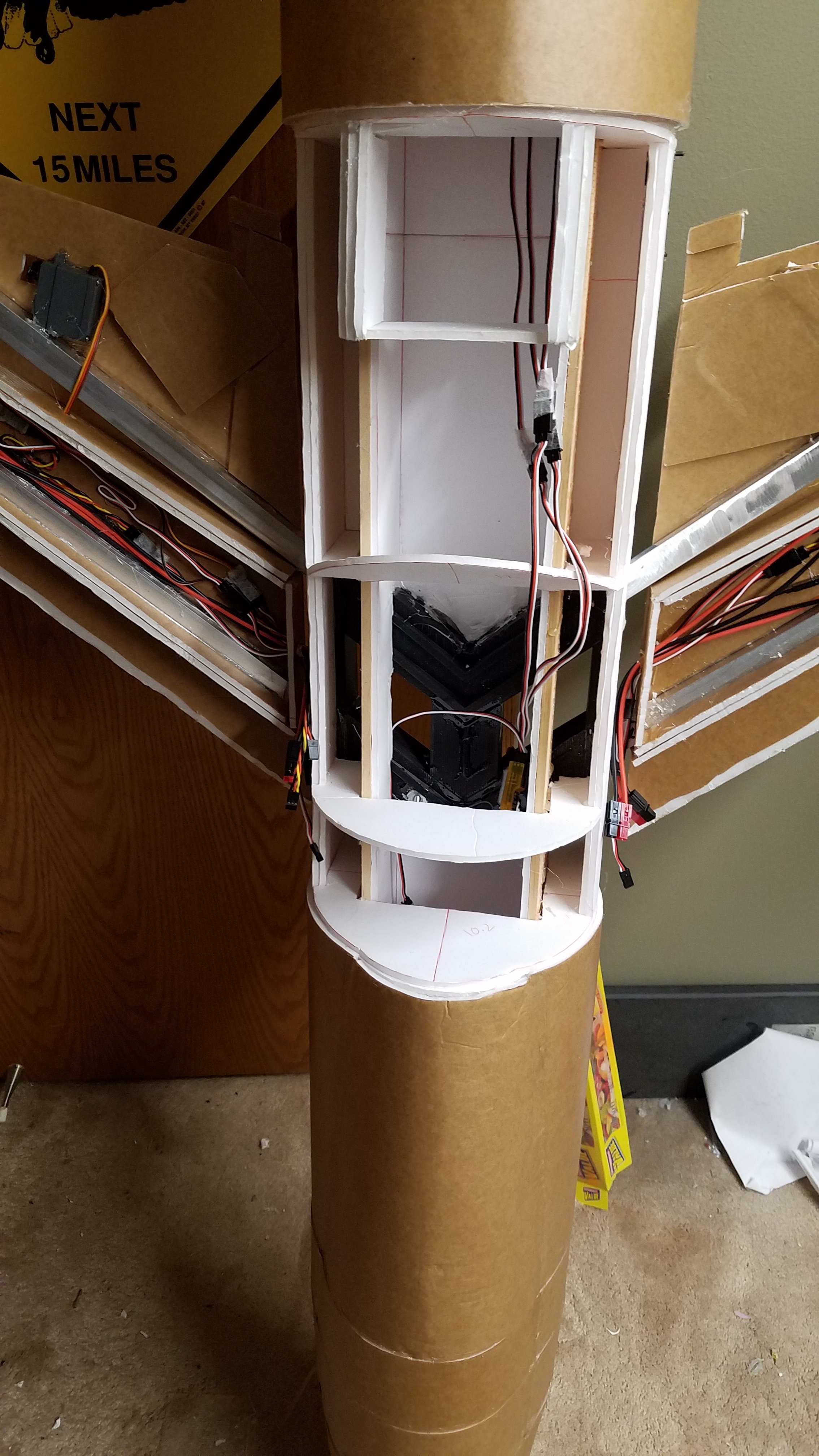
In the end I decided to use a 3D printed bracket in the fuselage to accept aluminum tubes embedded in the wings. The bracket is printed using PLA. I have a friend who works at a company with an industrial 3D printer, and I was able to get him to print the housing for me. I strength testing the bracket I was able to load it with 120 lbs without any damage occurring.
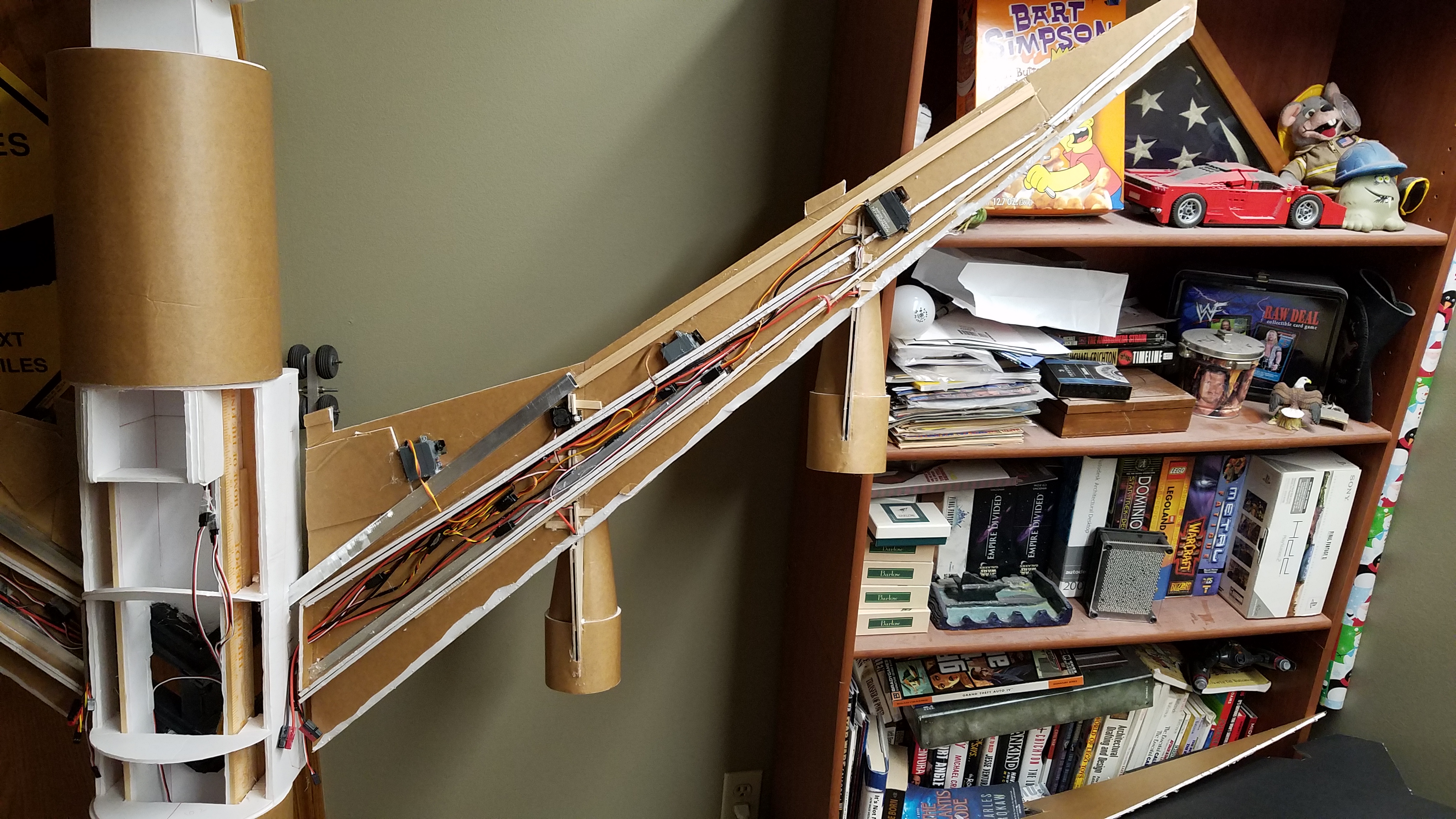
The wings are foamboard shells with foarmboard spars reinforced using yard sticks. As the wings were closed up I filled them with expanding foam. The EDF’s are mounted to the wings using plywood brackets. The control surfaces include inner and outer flaps and alerions. I had initially built the wings with the small ailerons between the flaps, however after initial testing they weren’t able to hold up to the forces needed because of the size of the hinges. I ended removing the aileron function of them and converted them to be ridged.
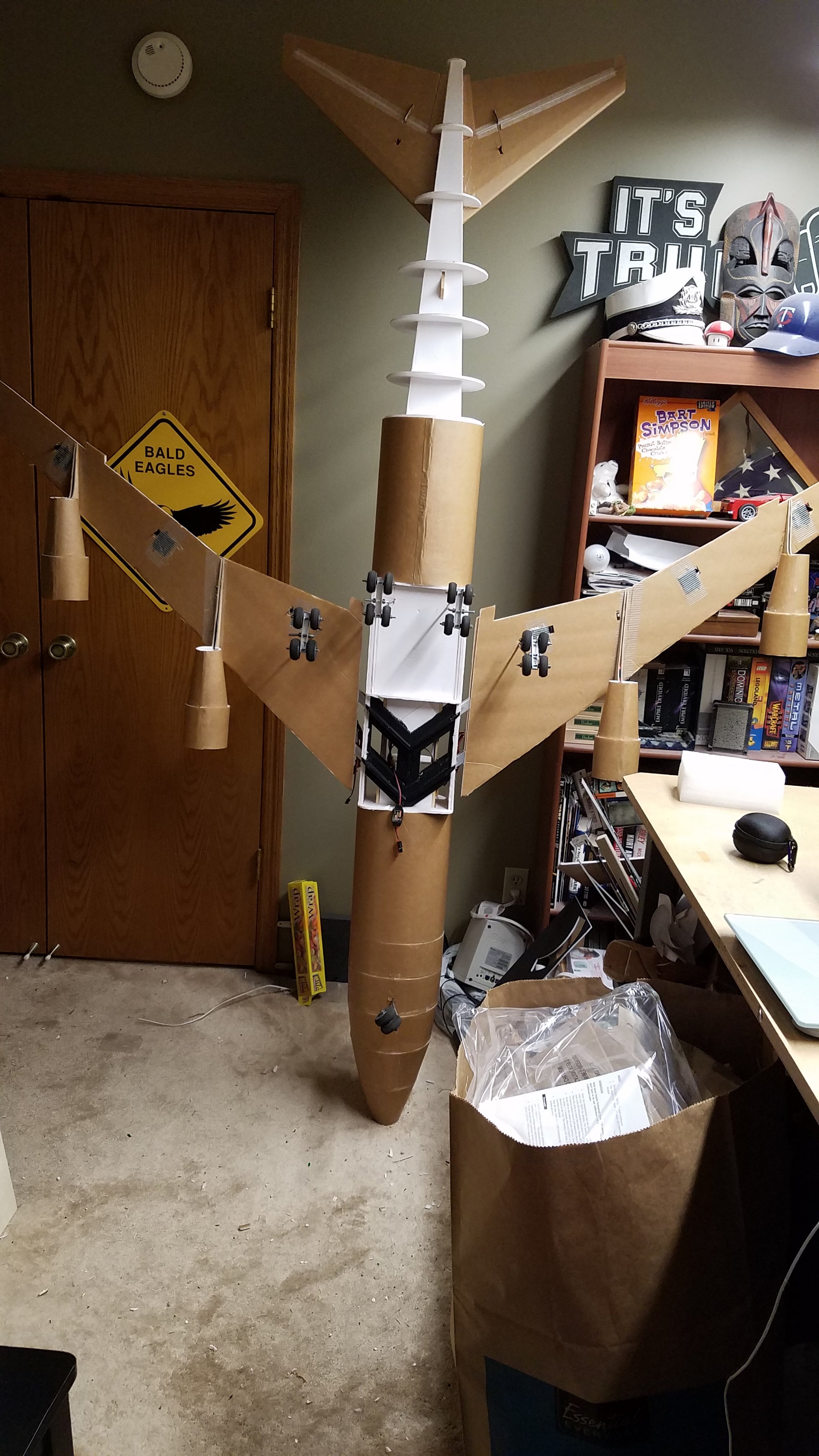
Initially I had investigated using retracts on the plane. But due to the cost and complexity of installing them I opted to use fixed landing gear. I wanted the landing gear to look as realistic as possible, so the plane has 4 sets of main landing gear, each utilizing a 4 wheel bogy. I also used 2 wheels on the nose gear, mostly as a function of distributing the load that is places on them. For the design of the bogies, I used the same design from a few of my previous planes. This utilized bent wire structs that attach to an aluminum channel that the wheels are attached to.
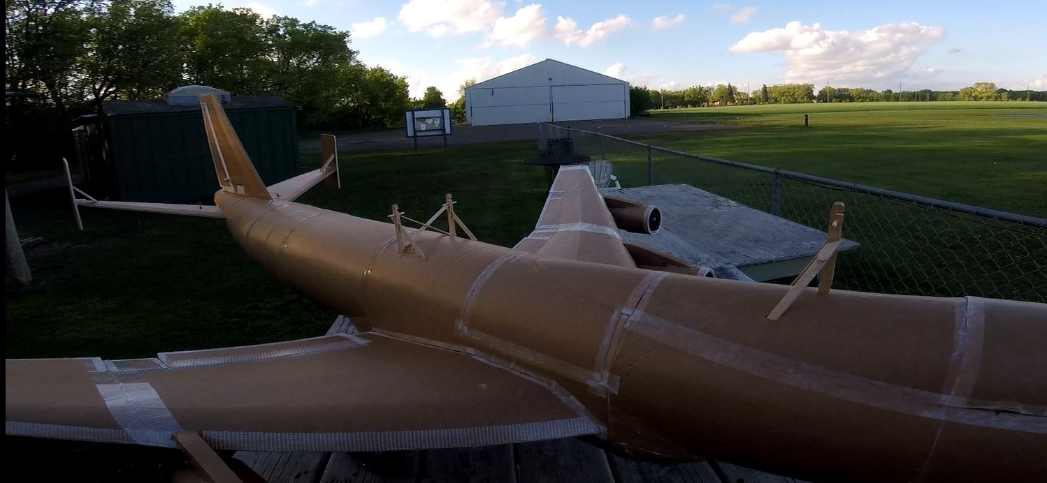
When working to figure out how to allow for the 747 and shuttle to separate I decided it would be easier to have the release mechanism controlled by the shuttle pilot. The struts on the 747 are built using popsicle sticks, paint sticks and BBQ skewers. I modified their configuration some from how they are on the actual plane in an attempt to give them some additional strength. The tops of the struts fit into the bottom of the shuttle with the shuttle resting on pieces of BBQ skewers that pass though the struts. Inside the shuttle are 3 servos, one for each connection point. They hold/release the shuttle by having the servo arms swing into/out of notches at the top of the struts. When testing the strength of these I was able to put my hand under and shuttle and lift the entire 747 up by simply picking up the shuttle.
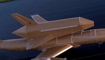
The space shuttle it’s self is designed to be as light as possible. It is constructed using a box fuselage with a few formers for the rounded top. For access inside the shuttle I made it so the back opens like the cargo bay doors on the real shuttle. These are held closed by a series of imbedded magnets.
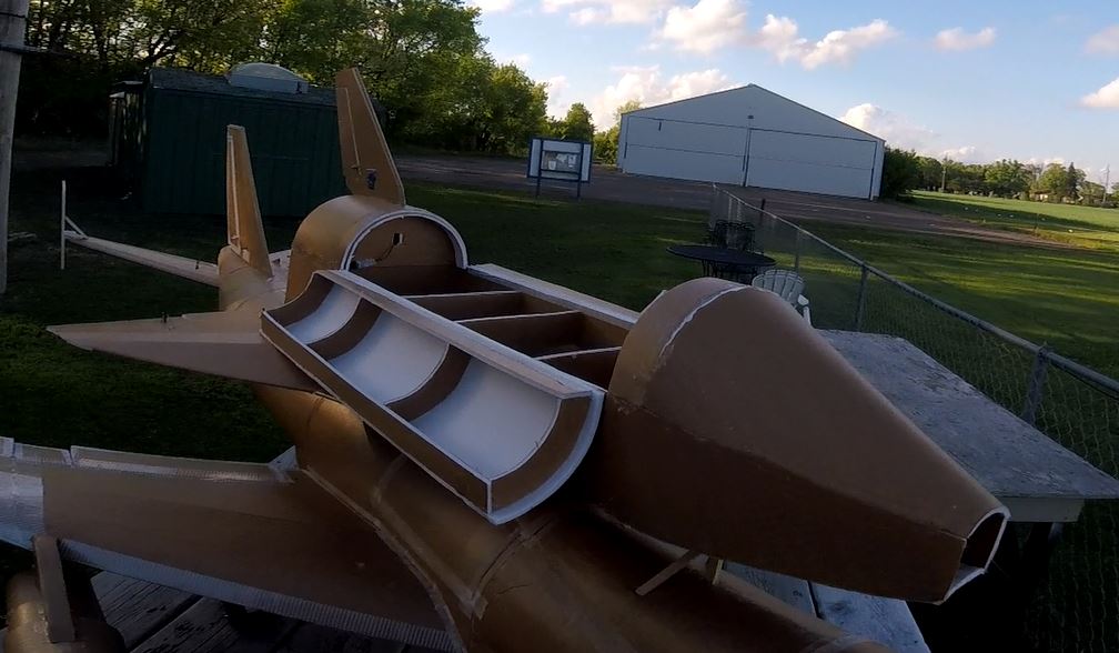
The wings are constructed with separate ailerons and elevators, and there is a functioning rudder. The shuttle is also built with the tail cone being removable. This will allow for me to make various tail cones to put on such as the current one for glided flights, one with a motor in it for powered flights, and maybe one day one that can utilize model rocket engines.
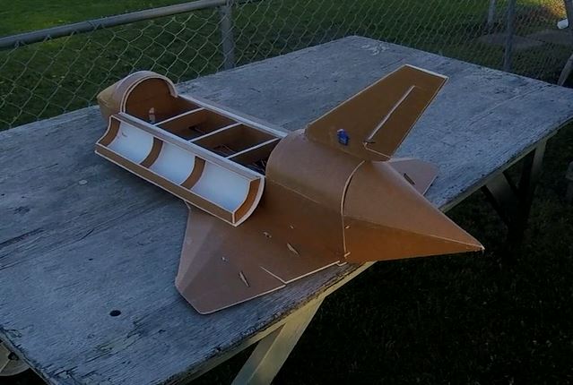
I was able to do an initial taxi test of the 747 about a month and a half ago.
During the test things seemed to go good, it appeared to have plenty of power. However, when I took it out for its maiden flight it wasn’t able to get going fast enough to take off. All in the plane should have been able to produce 16.25 lbs. of thrust, and with the plane only weighing 17.5 lbs. it should have flown. After taking it home I put the plane’s nose on a scale for a thrust test. It turns out I was only getting 4.5 lbs of thrust. After going through several things to figure out what was wrong I was able to identify 2 reasons for the lack of thrust.
After fixing these issues I took the 747 back to the field the following weekend for another attempt at a maiden.
It flew! It was very stable in the air and needed only a few clicks of aileron trim. A few discoveries from the flight were:
After knowing the plane could fly I made the above modifications as well as finished skinning the plane, added the additional vertical stabilizers at the tips of the horizontal stabilizers, replaced the thrust tubes on the engines with properly sized ones, and installed the mounting struts for the shuttle.
I also finally got around to building (enough of) the shuttle.
It was a few weeks before I was able to complete things and for weather to cooperate. Finally, the other day I was able to get everything out to the field for a test flight.
Everything could not have gone better. The club member, Chris, who flew the 747 for me was able to help me get the CG correct on the shuttle (Where I anticipated it being was way off). With the shuttle the 747 had to fly at full throttle, but was still bel to clime at a good rate. The separation went better than expected, and the shuttle was able to glide down beautifully (once I remembered rudder is a thing)
I still have some clean up on the 747 including putting a new nose on, cleaning up the tail of the fuselage and painting it.
On the shuttle I need to install a nose, put the cockpit/canopy on, and add bump outs at the tail for the 2 thruster pods. I will be working on these over the next few weeks.
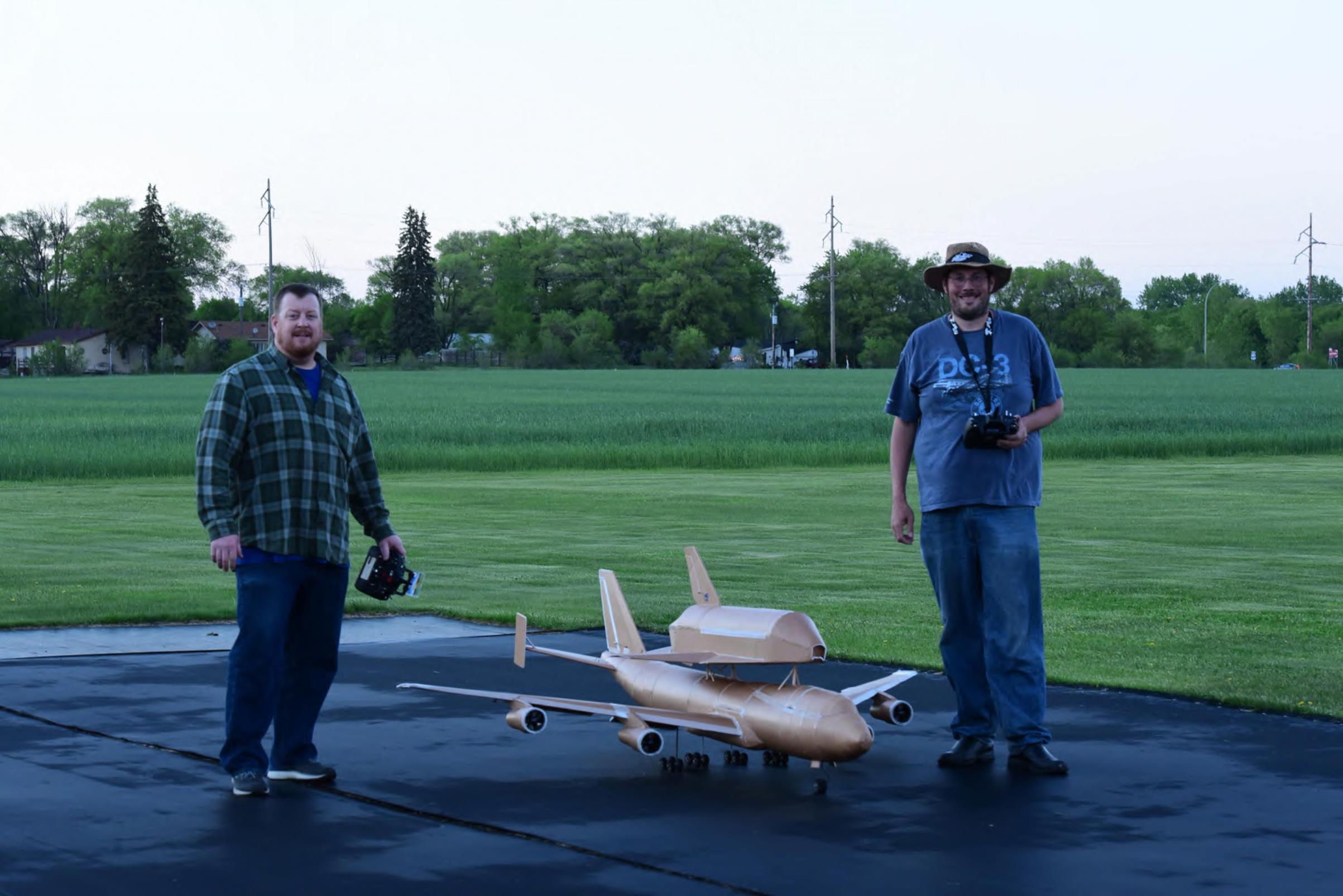
I could not be happier with how the project has turned out including how well both craft fly. I am looking forward to may (short) flights with both of these aircraft.

The NASA Shuttle Carrier Aircraft are Boeing 747-100 that were used to ferry the space shuttles from their landing site to the launch facility at Kennedy Space Center. The first of these aircraft was built in 1976 from a surplus 747 purchased from American Airlines. The Second was built in 1990 from a Surplus 747 from Japan Airlines.

I have been planning to build this plane for over a year now and finally got around to starting it earlier this year. My intent for the project is to build the 747 to take off carrying the space shuttle. Once the plane gets up to altitude the shuttle will be able to separate and be flown back to ground.
I wanted to build the plane as large as I could and still fit it in my car. This puts the Fuselage at 8’-9” long. With that determined here are specifications:
747 Specifications:
- 7'-9" wingspan
- 8'-9" overall plane length.
- Weight without Shuttle 18 lbs.
- (4) 70mm edf's
- (4) 4s 4000mah batteries
- 9 channel receiver
- (2) ailerons
- (2) flaps
- (2) elevators
- Rudder
- Nose Gear
- Throttle
- (18) 1 3/4" wheels
- (4) 4 wheel bogeys
- (2) front wheels
Space Shuttle Specifications:
- 2’-7” wingspan
- 4’-6” overall length
- Weight just over 2 lbs.
- Glider
- 3s 2200mah battery to power receiver (Bigger than it needs to be to get proper CG)
- 6 channel receiver
- Ailerons
- Elevator
- Rudder
- Release Mechanism
- Throttle (Future)
The 747 fuselage is built using a center foamboard box spar with formers. These are wrapped in foarmbard sheets. Wooden yard sticks run the length of the fuselage attached to the box spar to structurally reinforcing in the fuselage. Paint sticks are used as the spar in the vertical and horizontal stabilizers.

I investigated several options for attaching the wings to the fuselage. With the swept wings of the 747 and the dihedral they have, it is not possible to have a removable spar that runs between them. I investigated using an aluminum tube frame, but in order to get tubing in a size/thickness that would have worked would was rather expensive.

In the end I decided to use a 3D printed bracket in the fuselage to accept aluminum tubes embedded in the wings. The bracket is printed using PLA. I have a friend who works at a company with an industrial 3D printer, and I was able to get him to print the housing for me. I strength testing the bracket I was able to load it with 120 lbs without any damage occurring.

The wings are foamboard shells with foarmboard spars reinforced using yard sticks. As the wings were closed up I filled them with expanding foam. The EDF’s are mounted to the wings using plywood brackets. The control surfaces include inner and outer flaps and alerions. I had initially built the wings with the small ailerons between the flaps, however after initial testing they weren’t able to hold up to the forces needed because of the size of the hinges. I ended removing the aileron function of them and converted them to be ridged.

Initially I had investigated using retracts on the plane. But due to the cost and complexity of installing them I opted to use fixed landing gear. I wanted the landing gear to look as realistic as possible, so the plane has 4 sets of main landing gear, each utilizing a 4 wheel bogy. I also used 2 wheels on the nose gear, mostly as a function of distributing the load that is places on them. For the design of the bogies, I used the same design from a few of my previous planes. This utilized bent wire structs that attach to an aluminum channel that the wheels are attached to.

When working to figure out how to allow for the 747 and shuttle to separate I decided it would be easier to have the release mechanism controlled by the shuttle pilot. The struts on the 747 are built using popsicle sticks, paint sticks and BBQ skewers. I modified their configuration some from how they are on the actual plane in an attempt to give them some additional strength. The tops of the struts fit into the bottom of the shuttle with the shuttle resting on pieces of BBQ skewers that pass though the struts. Inside the shuttle are 3 servos, one for each connection point. They hold/release the shuttle by having the servo arms swing into/out of notches at the top of the struts. When testing the strength of these I was able to put my hand under and shuttle and lift the entire 747 up by simply picking up the shuttle.

The space shuttle it’s self is designed to be as light as possible. It is constructed using a box fuselage with a few formers for the rounded top. For access inside the shuttle I made it so the back opens like the cargo bay doors on the real shuttle. These are held closed by a series of imbedded magnets.

The wings are constructed with separate ailerons and elevators, and there is a functioning rudder. The shuttle is also built with the tail cone being removable. This will allow for me to make various tail cones to put on such as the current one for glided flights, one with a motor in it for powered flights, and maybe one day one that can utilize model rocket engines.

I was able to do an initial taxi test of the 747 about a month and a half ago.
During the test things seemed to go good, it appeared to have plenty of power. However, when I took it out for its maiden flight it wasn’t able to get going fast enough to take off. All in the plane should have been able to produce 16.25 lbs. of thrust, and with the plane only weighing 17.5 lbs. it should have flown. After taking it home I put the plane’s nose on a scale for a thrust test. It turns out I was only getting 4.5 lbs of thrust. After going through several things to figure out what was wrong I was able to identify 2 reasons for the lack of thrust.
- I had not properly calibrated the throttle range on the ESC’s. The ESC’s I bought had a different calibration routine than I was use to (who reads instructions) so after completing the overly complicated calibration process I had that fixed.
- I had screwed up my calculation on the size of the thrust tube discharge. It was at 60% of what it should have been. To fix this I shortened them up till the discharge was the proper size.
After fixing these issues I took the 747 back to the field the following weekend for another attempt at a maiden.
It flew! It was very stable in the air and needed only a few clicks of aileron trim. A few discoveries from the flight were:
- I needed to increase the throws of the ruder and ailerons.
- I needed to get some airflow through the fuselage to cool the batteries.
- After a 2:15 flight there was only 50% battery left, so I needed to make provisions to be able to add 4 additional batteries.
After knowing the plane could fly I made the above modifications as well as finished skinning the plane, added the additional vertical stabilizers at the tips of the horizontal stabilizers, replaced the thrust tubes on the engines with properly sized ones, and installed the mounting struts for the shuttle.
I also finally got around to building (enough of) the shuttle.
It was a few weeks before I was able to complete things and for weather to cooperate. Finally, the other day I was able to get everything out to the field for a test flight.
Everything could not have gone better. The club member, Chris, who flew the 747 for me was able to help me get the CG correct on the shuttle (Where I anticipated it being was way off). With the shuttle the 747 had to fly at full throttle, but was still bel to clime at a good rate. The separation went better than expected, and the shuttle was able to glide down beautifully (once I remembered rudder is a thing)
I still have some clean up on the 747 including putting a new nose on, cleaning up the tail of the fuselage and painting it.
On the shuttle I need to install a nose, put the cockpit/canopy on, and add bump outs at the tail for the 2 thruster pods. I will be working on these over the next few weeks.

I could not be happier with how the project has turned out including how well both craft fly. I am looking forward to may (short) flights with both of these aircraft.
Last edited:


