FTFC'18 WWII Vought XF5U "Flying Flapjack" designed by SP0NZ & LocalFiend

localfiend

I like 3D printers...
Mentor


And kersplat again lol. Got one flight and landing, and then another flight with more of a crash into a bunch trees instead of landing.

Think I was pushing the CG back too far trying to gain elevator authority. Flew fine until I touched the rudder and the plane went nuts. Big time yaw instability with differential thrust input.

I'm repairing the damage, adding slightly bigger rudders and adjusting control surfaces instead of pushing CG back further. Both the V-173 and XF5U had full flying tailevator thingies. On mine, the outer surfaces were only ailerons. I'm going to make them act like elevons and see if that's enough.

If not, I'll increase the outer control surface size. And if that doesn't do it, I guess I'll be going with full flying surfaces. Shouldn't be too hard to do, they're already separate pieces after all.
 

Michael9865

Elite member
Great job. Looks like it flies good even with some authority deficiencies that you pointed out.
 
Last edited:

localfiend

I like 3D printers...
Mentor

I eyeballed a few of those when the project first started. Look like fun little fast to build planes. Thought about testing a profile version out first, but since time was limited, I just went all out.


Got to try out the rebuilt version this afternoon. Adjusting the size of the rear control surfaces made all the difference. Moved the CG back up to my first guess and the thing flew great, although, I had an awful lot of control throw at the start. Jumps right into the air at half throttle lol.

https://youtu.be/kvxVbOERFT8


Needed a bit of up trim, about 8 degrees. Dunno if it needs reflex like a wing, but it flew nicely setup that way. Might be able to get rid of some of that by moving CG back a hair, but this is a nice safe setting. I think that like a nutball, the CG range is pretty large. The previous flight had the CG back a full extra inch from what it was here.

Other than that, I'm pretty happy with how it went. Had to land kind of abruptly as someone pulled up, but my soft welding wire landing gear did it's job and folded. :D Probably woulda just bounced a bit with proper wire. Oh well.

Got my changes to the parts sent off to Dan and he's hard at work getting the plans ready. I need to get off my butt and finish the build log, as well as upload some of the 3D printable parts.
 

localfiend

I like 3D printers...
Mentor
And now for more of the build log....


Grab the main cockpit piece

REF75
U3jQStO.png


Remove paper, bevel, and pre-bend as shown.

REF76
E8nBbq0.png


Either cut off both end tabs and glue as I did here, or only cut of one tab, remove the foam from the other side, and use the remaining paper flap to help glue things together flight test style. I like to put tabs on both sides of rings where possible, as it helps you to get the proper bend at the tips of your curve.

REF77
J6U7P4O.png


Glue the back half like so:

REF78
Pz7iNR7.png


Here's what it should look like. Don't fit it up to the plane yet. If you try now, the piece will likely tear.

REF79
Q0sCtrI.png


Grab the next cockpit piece.

REF80
GKg8WQU.png


Remove paper and pre-bend.

REF81
mio5xQ3.png


Start gluing it up to the main section like this. I like to go a little bit at a time, only using enough glue that it covers all the foam area without spilling out and over the paper. If you have some extra glue no big deal, just wipe it off with your finger after it cools slightly, or more quickly with a piece of scrap foam.

REF82
9yNYvX2.png


Continue like this all the way around.

REF83
7qO4oZJ.png


Grab the next cockpit piece, remove paper, and prebend.

REF84
iK1mOij.png


Cut off the tabs like before, or do the alternate and glue together. After gluing you'll see that the foam bulges out a little bit. For the cleanest fit, I like to shave that off.

REF85
ZgoEy8I.png


You don't have to remove much.

REF86
8eWSNj0.png


Start gluing it in place the same way you did with the other section.

REF87
HIxlUfE.png


All glued up.

REF88
zz16VXA.png


Grab the nose circle piece, and remove the outer ring of foam. To make it as clean as possible, I like to hold it against the table, and quickly slice through the paper and flick off the small pieces.

REF89
ZN3zIb9.png


Glue it into place on the nose. I like to add glue, set the nose piece on the table, and slide the rest of the assembly onto it. Makes it easy to make things straight and clean.

REF90
INo0c9m.png


Next grab the back cockpit section, remove paper, bevel, and pre bend.

REF91
UwIPnJe.png


Glue into place. I generally do this in sections just like the other cockpit pieces.

REF92
SsVJ9DG.png


Now you can go ahead and do a test fit. Check things out, then set it aside. It'l be easier to work on the plane if we wait to glue it in place.

REF93
qiaQEDy.png


Time for the intake covers.

REF94
ZXQecAk.png


Remove paper, bevel, and pre-bend.

REF95
KTRmykl.png


Then you can start gluing it together. The trick here is to use as little glue as possible, don't let the nozzle of the glue gun touch the foam, and hold the pieces until the glue dries completely. It's not hard, it's just all about patience. Keep in mind that you can add more glue to the back side after you glue up a joint, so it's not a problem to go light for the first pass.

REF96
8pBVwC6.png


Here you can see about how much glue I use. You can squirt on a little more and squish it down along the seam.

REF97
CHtI6sE.png


Alternate side to side and work your way forward.

REF98
qUgdeNz.png


All done. Just 3 more to go.

REF99
nJ8895u.png


Once you finish all 4, you can glue on the back piece. Remove paper, bevel, prebend like usual.

REF100
Agw753v.png


Glue into place. I like to do one half at a time.

REF101
pgsyYq6.png


Go ahead and do a test fitup if you like. Helps to make sure you have enough bend for it to fit cleanly before gluing.

REF102
R0cgFYq.png


Before stuff gets glued on however, do the intake tubes. Remove paper and pre-bend.

REF103
v55YH5k.png


Like other circles, either cut off both tabs and glue, or do it FT style with a tab on one side.

REF104
LHV9G3K.png


Grab an outer ring and remove the paper from one side.

REF105
eWr6AfR.png


Glue it onto the angled section of the intake tube. The inner diameters should match up.

REF106
3oFP8OS.png


Glue the intake tube and ring into place like so. Before gluing I like to smooth the exposed foam with a bit of sand paper.

REF107
LHJdjMw.png


Now you can glue it into place. I like to glue it all in one go. It's easiest if you take your time and make sure all of your bends are close. You can also do it in sections. Glue the bit by the intake ring first, then carefully add glue to the rest.

You can cleanly progressively add glue to something like this by taking a piece of scrap paper, adding a drop of glue to it, then sliding it under the part where you want the glue to go. Push down on the part and pull out the paper. Tada lol.

Make note of the alignment marks in picture 109.

REF108
UcHaWTZ.png


Here's the alignment marks on the parts. Should line up with the seam on the outer skin.

REF109
11iiEyG.png


Go ahead and glue up the top of both sides. We'll save the bottoms for later.

REF110
afVTCDu.png


Now the wingtips. You could just laminate layers of foam, glue them to the wingtips, and sand to the proper curve. But this part really isn't that bad if you've already made the cockpit and the air intakes.

Like usual, remove the paper, and bevel.

REF111
iIPscNm.png


You'll want to pre-bend as well. You can see I've glued one section in the back. Do it just the same as the intake covers, alternating sides starting from the back.

REF112
5IuFHDf.png


Should look like this when done:

REF113
IAkkmlq.png


You'll probably need to bend it some more. Don't be afraid to squish it a little.

REF114
THITzAa.png


You'll want it to have enough bend that it can be pressed flat on a table like so:

REF115
x6QUznj.png
 

localfiend

I like 3D printers...
Mentor
Dan worked late last night and got the plans all ready to go.

These are as complete as the plane is now and has all the parts. A new version of them will likely be coming out that details stuff like all my bevels, part orientation, paper removal, cavities etc, but in the meantime, the pictures from the build log should do just as well or better.

All-In-One

Full-Size

Tiled A-Size Sheets

Tiled B-Size Sheets

The picture below shows how I lay out the parts on 20x30" dollar tree foam sheets for my CNC machine so that you can see proper orientation. If you cut out some parts against the grain, bending them won't be as easy.

partorientation.png

I'll be finishing the build log this evening. Right now I have some more flying to do. :D
 

SP0NZ

FT CAD Gremlin
Staff member
Admin
Moderator
Mentor
Dan worked late last night and got the plans all ready to go.

These are as complete as the plane is now and has all the parts. A new version of them will likely be coming out that details stuff like all my bevels, part orientation, paper removal, cavities etc, but in the meantime, the pictures from the build log should do just as well or better.

All-In-One

Full-Size

Tiled A-Size Sheets

Tiled B-Size Sheets

The picture below shows how I lay out the parts on 20x30" dollar tree foam sheets for my CNC machine so that you can see proper orientation. If you cut out some parts against the grain, bending them won't be as easy.

View attachment 99868

I'll be finishing the build log this evening. Right now I have some more flying to do. :D


I plan to have an updated set of plans out later this week.
 

localfiend

I like 3D printers...
Mentor
And here's the rest of the build log.

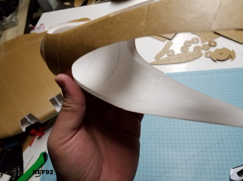
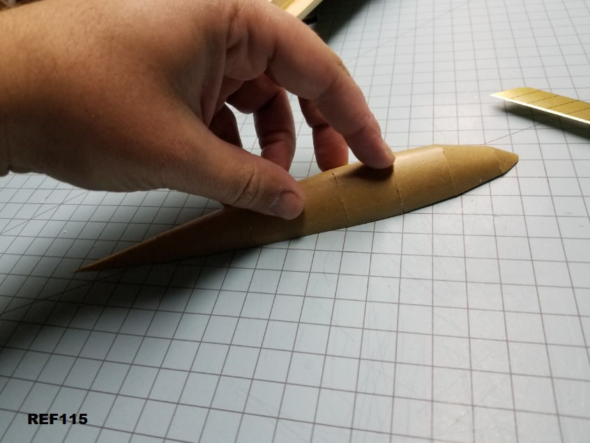
Glue up the top side of the wingtip. You can do this in sections if you're very careful, or if you use the piece of paper with glue on it trick.
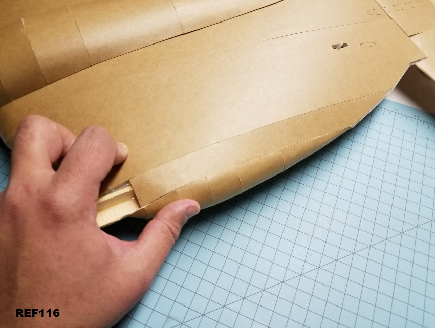
REF116
od6YlRx.png


Next, do the same thing to the bottom. If you need, you can squirt a little bit of extra glue inside now and smooth it down with a BBQ skewer to make sure the top half is well glued.

REF117
BGMCekp.png


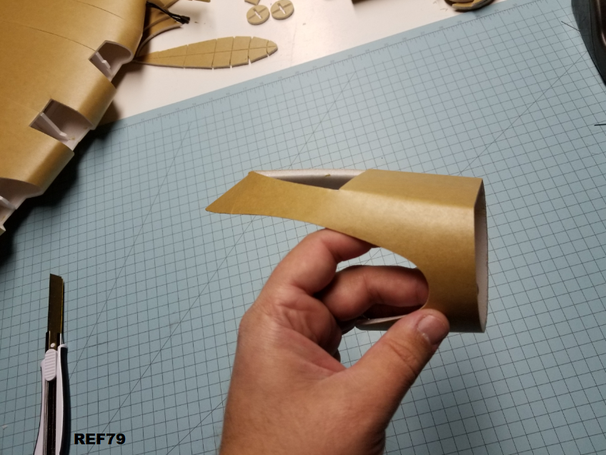
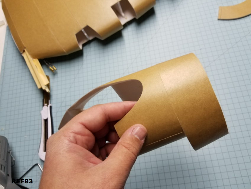
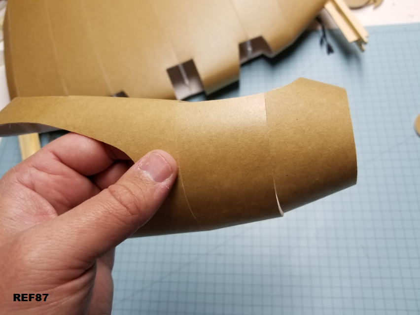
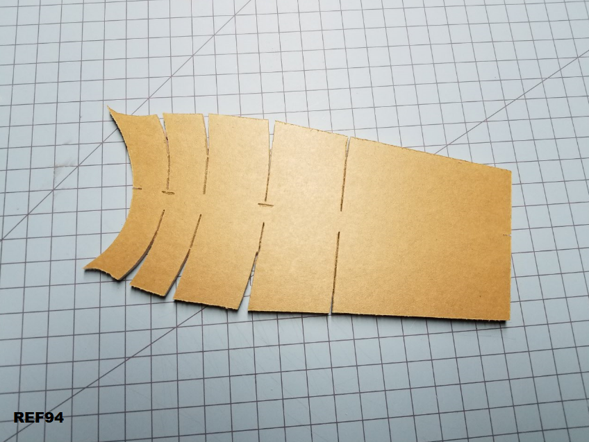
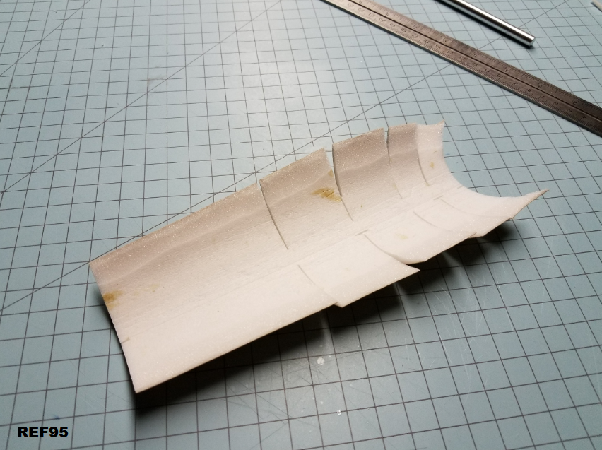
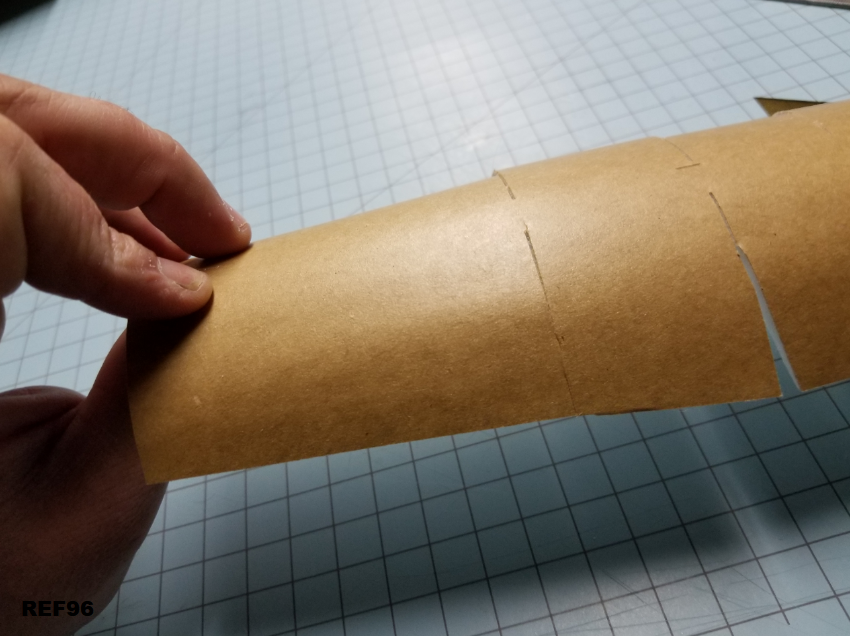
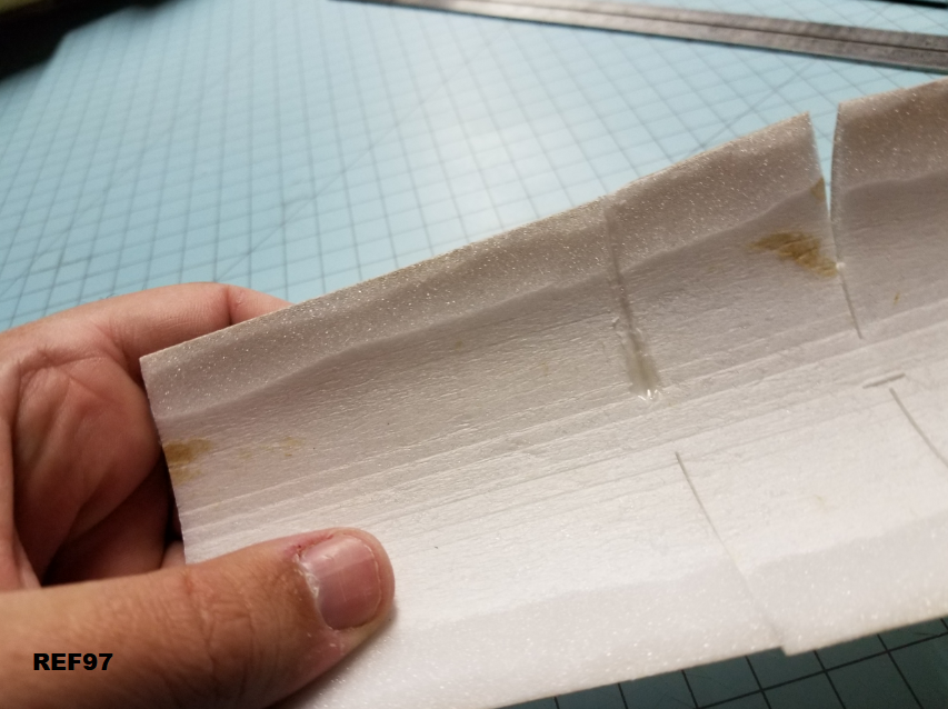
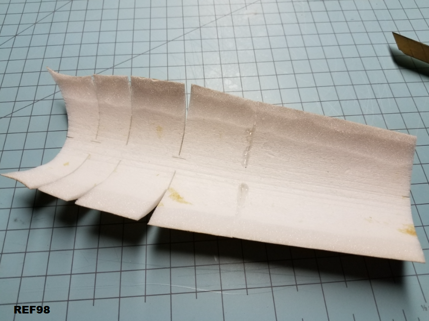
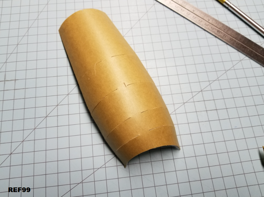
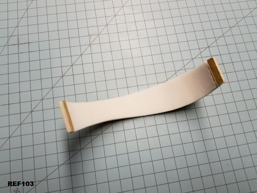
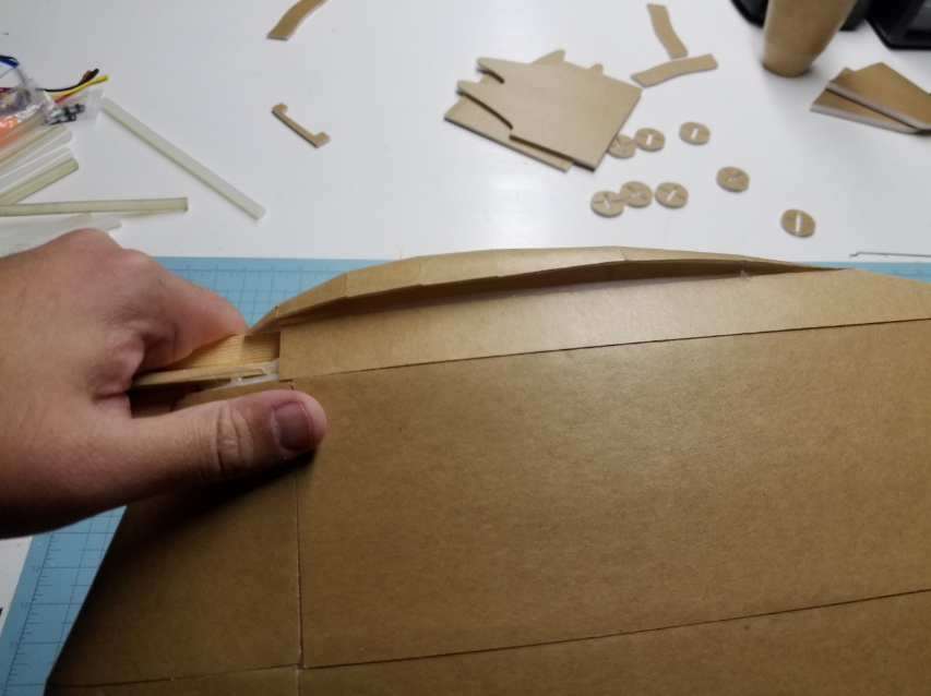
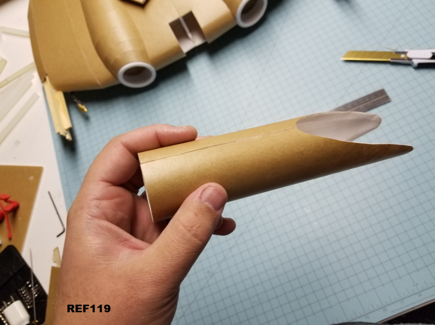
Grab the motor pylon tube thing, and do the usual. Remove paper, bevel, and pre bend like shown.
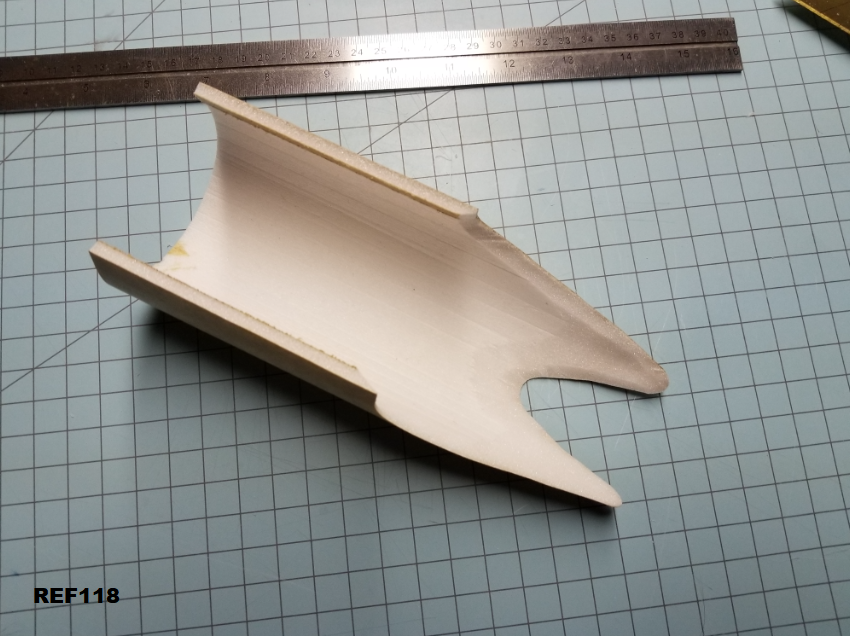
REF118
rVLV5ql.png


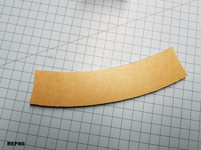
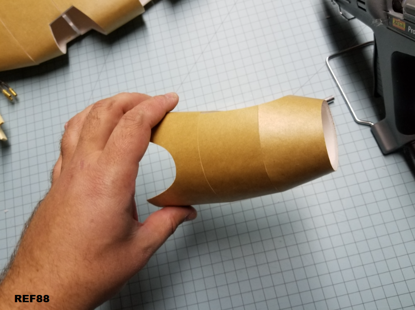
And also like usual, cut off both tabs and glue, or do it FT style with the flap.

REF119
WiWpq8f.png


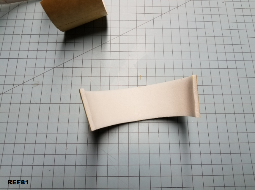
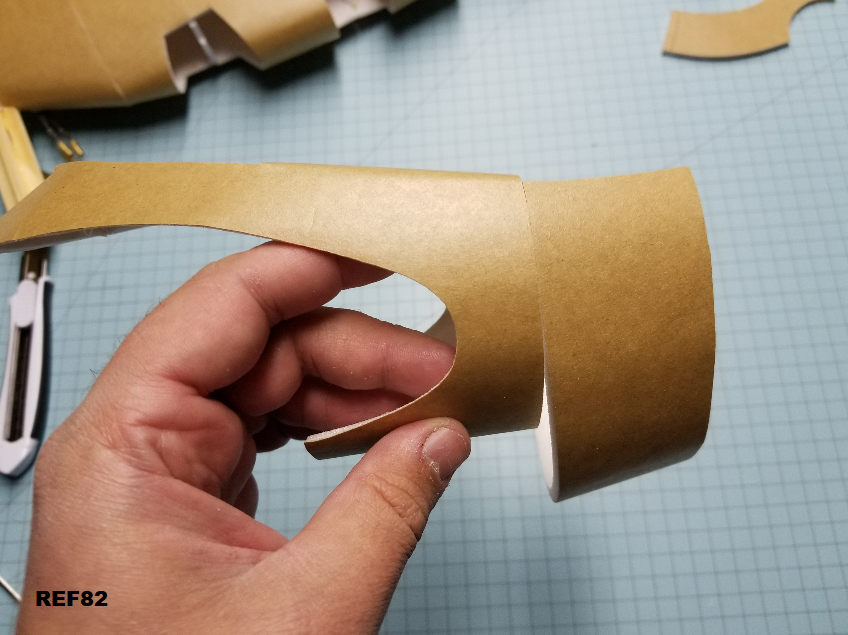
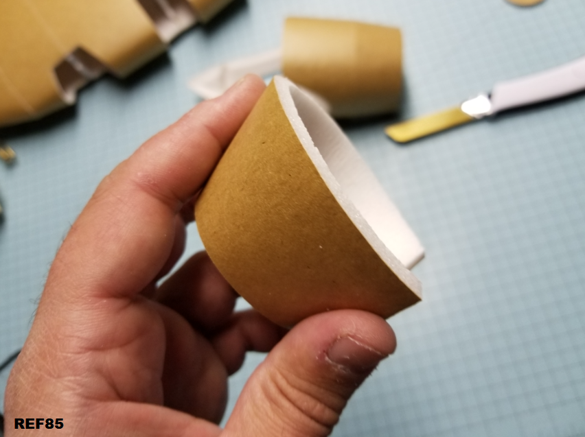
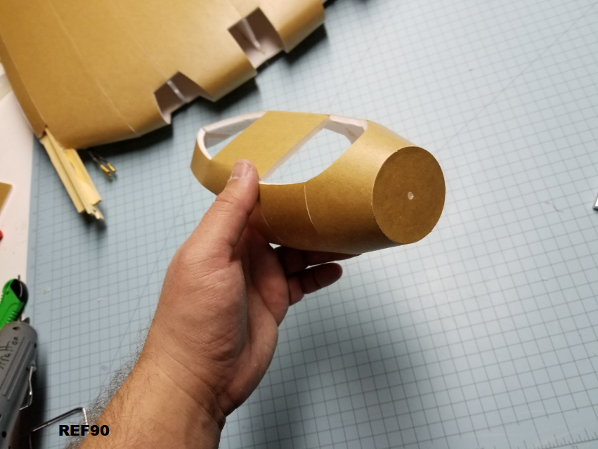
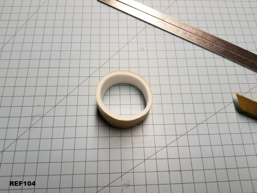
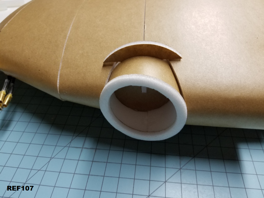
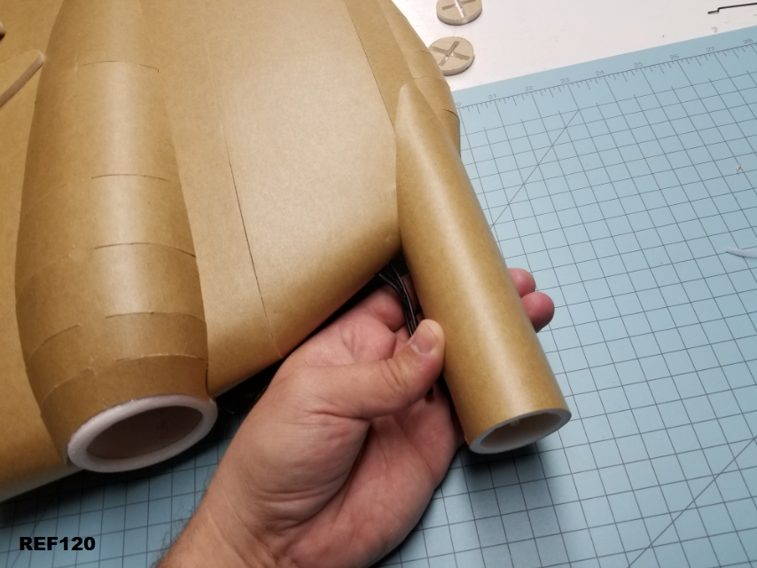
The tube simply slides on. Take your time here, make sure it fits nicely, is round, and is straight with the paint stick.

REF120
QnZn7ri.png


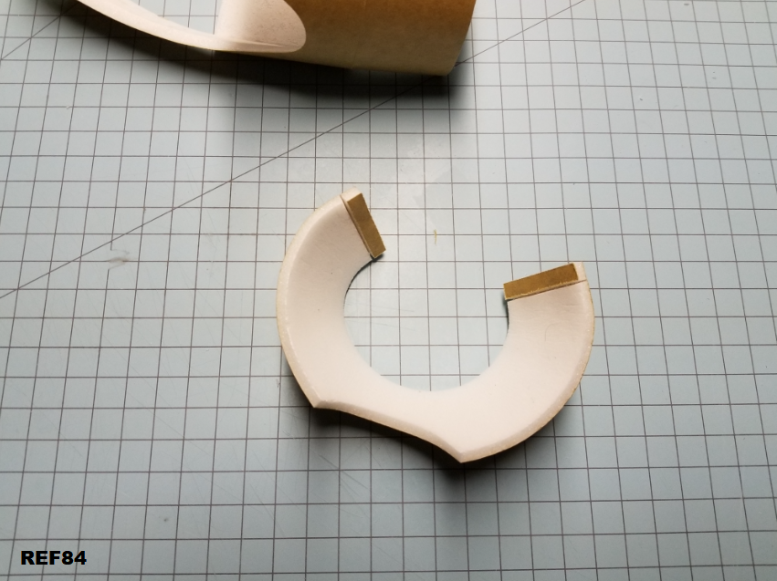
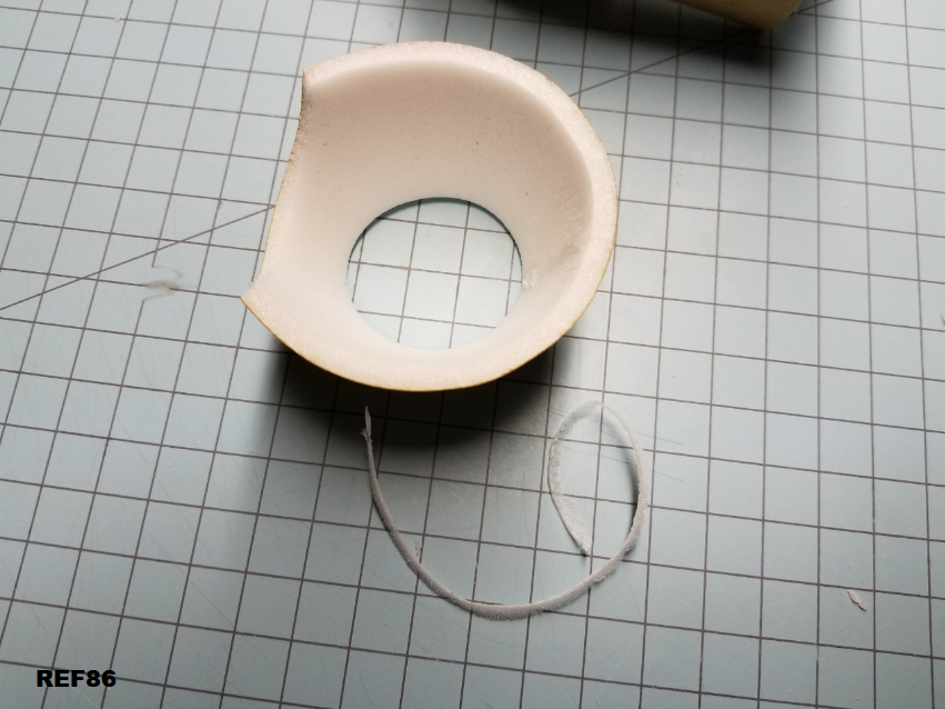
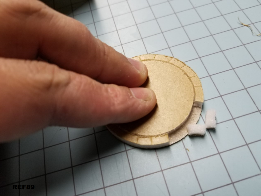
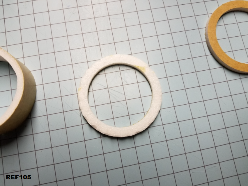
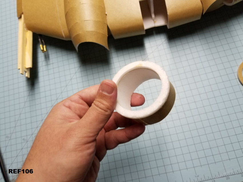
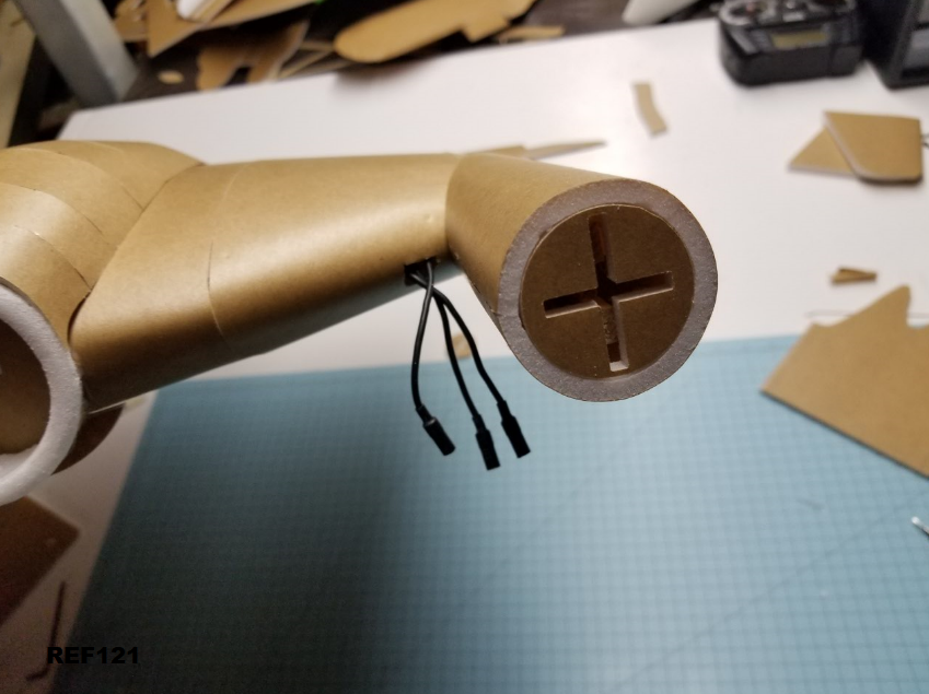
If you're using my 3D printed firewall, you don't need these circle pieces. I put 8 of them on the plans if you're going to use a simple firewall, push and glue a few of them into place. I only stuck one on the entrance here, cause I didn't want pieces of foam stuck in there getting in the way of the 3D printed firewall.

You can use a FT firewall, just trim to to match the circle. It's 1.75" diameter. A razorblade will do the trick if you're careful, then you can clean up with sandpaper.

REF121
ioUZjfd.png


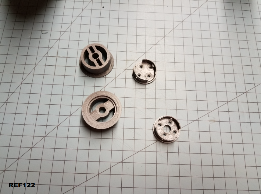
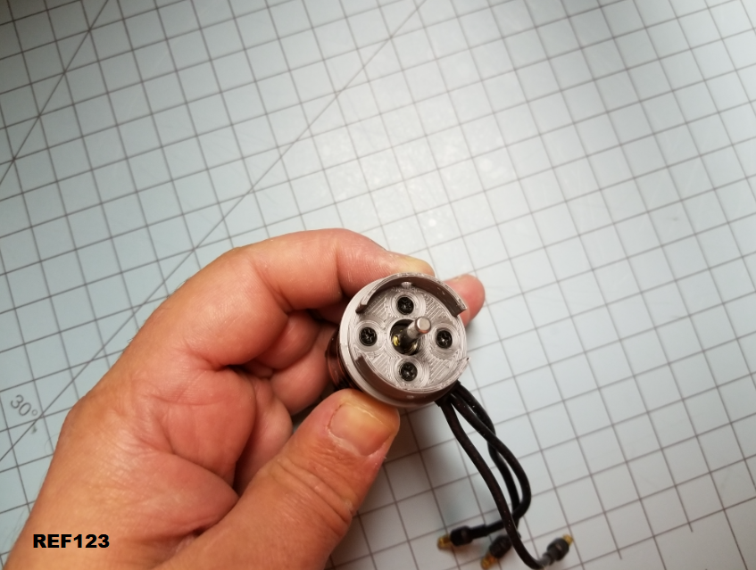
Here's the 2 piece 3D Printed firewall bits. These are sized to the Power Pack C motor (GT2215/09), but the bolt pattern fits pretty much all motors of a similar size.

The pieces with the bolt holes for the motors are different. There's a 90degree angle difference between the two of them so that you can get motor wire coming out at your preferred angle. I like my motor wires to be on the bottom pointing inwards toward the plane.

REF122
30pjoox.png


Here's the motor bolted up.

REF123
I3fqDrF.png


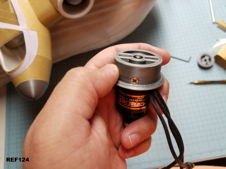
That piece slides into the main base and can be secured by a spare motor screw on each side. You could also CA these parts together.

REF124
SyChQmu.png


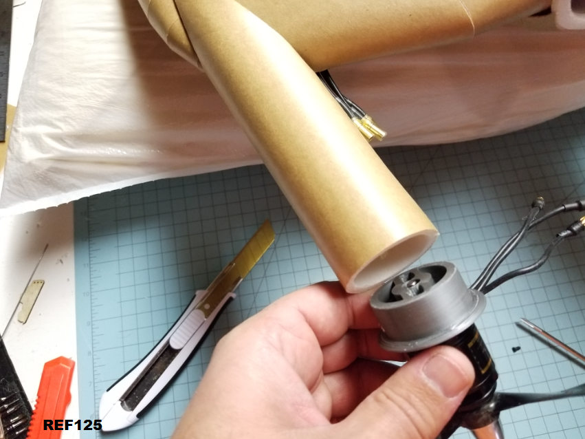
The part should just slip into the tube and over the paint stick. I've chamfered the 3D parts pretty well, but I suppose additional fitting could be needed. The 3D printed part is pretty beefy, and you can remove a bunch of material with something like a drill before it loses strength.

Make sure the part slides into place easily, and check to make sure you have it straight before using hot glue to fix it in place. I like to attach a prop to help me eyeball straightness.

REF125
4bDjS89.png


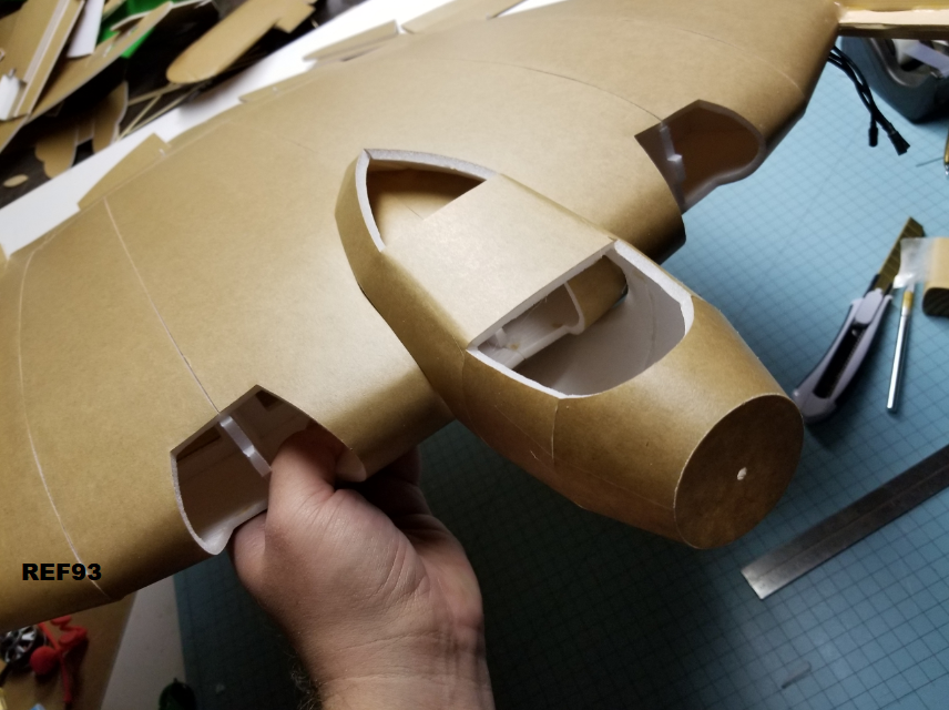
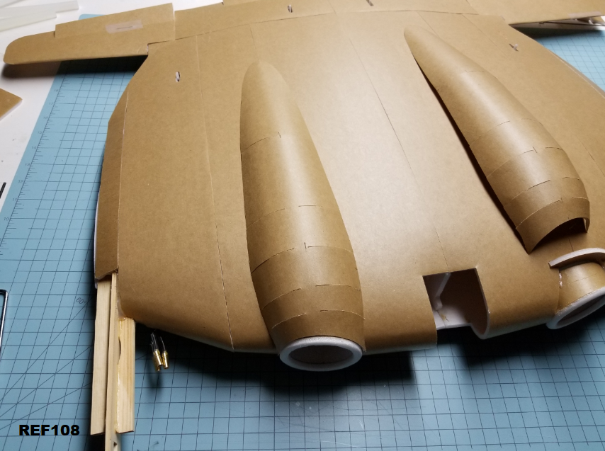
Now were at the point of just sticking all the other bits onto the plane. You can do the rudders now, it would also be a good time to glue on the bottom air intakes. I like to get an old pillow, put it in a trash bag, and use it as a plane rest. This thing can be awkward to work on at this stage, and the pillow really helps.

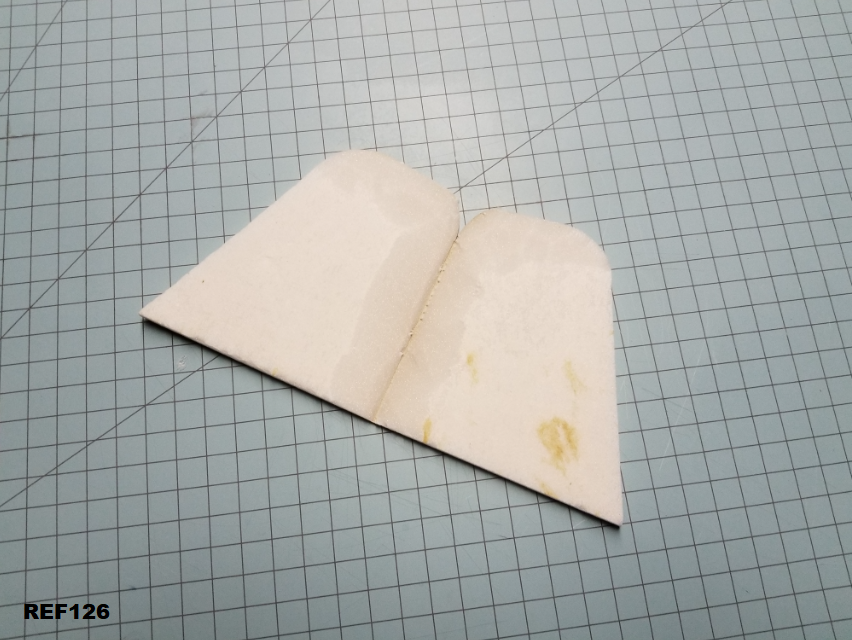
Like usual, remove paper and bevel. The rudders go together just like the tailevator sections. I didn't choose to cut out funtional rudders on this version, but the lines are included on the plans if you would like.

REF126
YbZqrPI.png


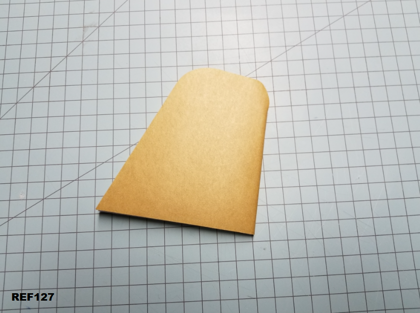
Add glue just like the tailevator and fold over.
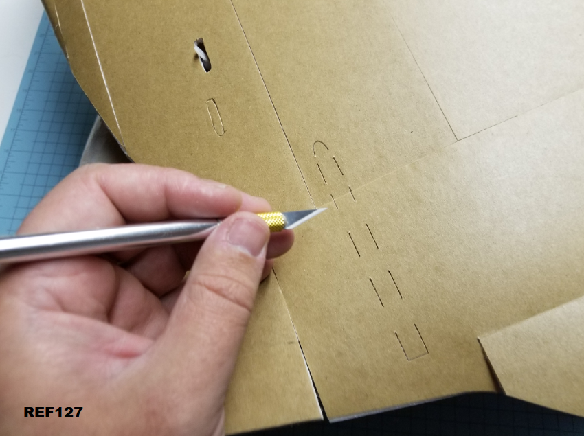
REF127
uEC59tS.png


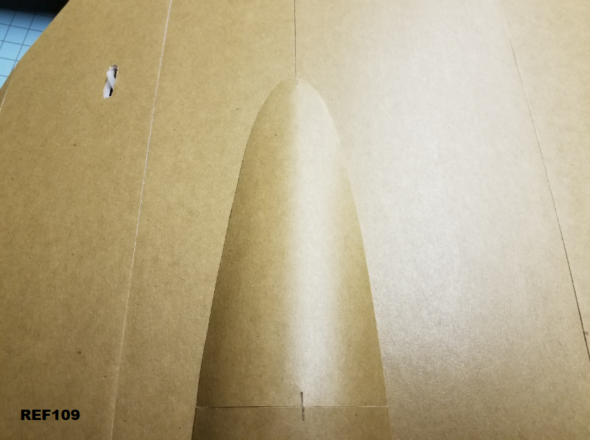
Go ahead and cut out the rest of the foam where the rudders go. If your lines don't match up perfectly, no big deal. Just stick the rudder in place and trace around it. I don't think the angles here matter too much as long as they're not extreme and both sides match.

REF128
YkYbArQ.png


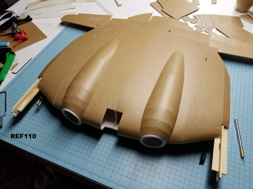
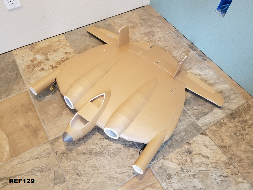
I didn't take any pictures to show gluing the rudders in place, but it's pretty simple. I put a slight outward tilt on them. Once again, I don't think this angle is critical. Just make both sides the same.

REF129
tQDZ64K.png


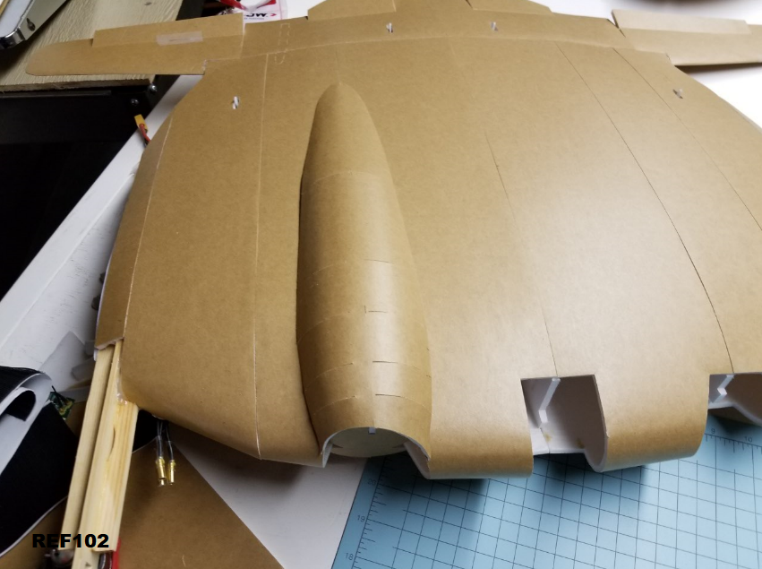
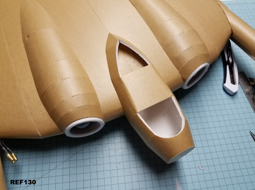
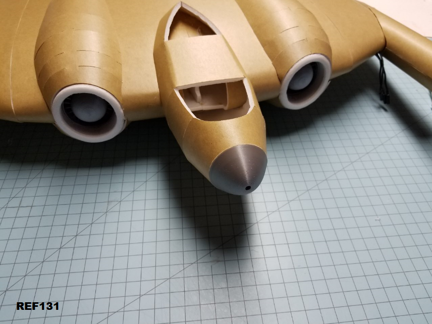
Take the finished cockpit section and glue it in place now. The point on the top, and the curve on the bottom match up to the center seam. Pretty straight forward.

REF130
qsKZ6aI.png


If you haven't already, go ahead and glue in the 3D printed cosmetic pieces if desired. I'll include a picture you can print out to have fake intakes if you desire. Or you can fab something up yourself.

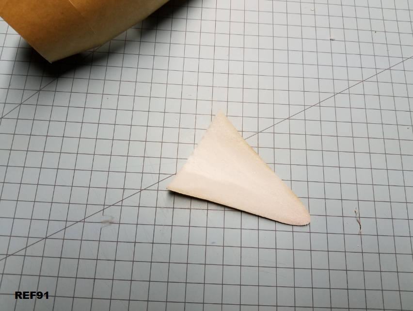
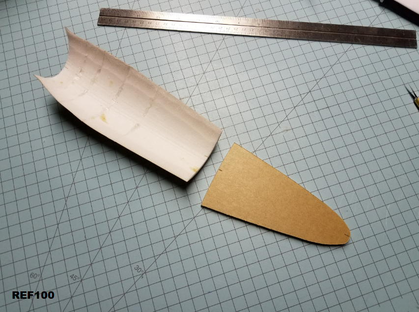
The nose piece can be made from laminated foam sections sanded to shape. Take some scrap foam, remove paper from both sides, and build up several layers of it. It's really quite easy to sand if you keep your hot glue in the center area and away from the edges you use to sand.

For painting exposed foam, a layer of elmers glue does well to make a surface layer to separate the foam from paint solvents. You can also use just about any form of wood putty etc...

REF131
4Id2WGV.png


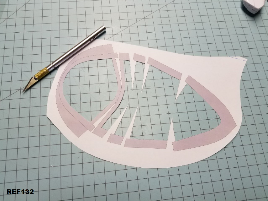
The canopy can be done a couple different ways. You can print it on paper and use as is, print it directly onto a printable overhead transparency, or do a combination of the two.

If you want to do the combo, print out on paper, and cut out the window areas.

REF132
gyuBnxe.png


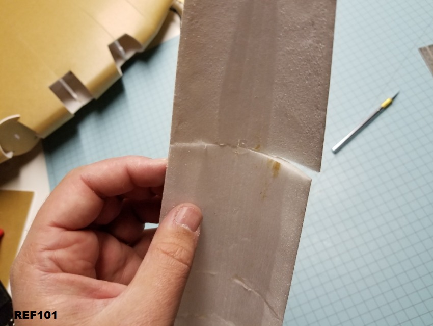
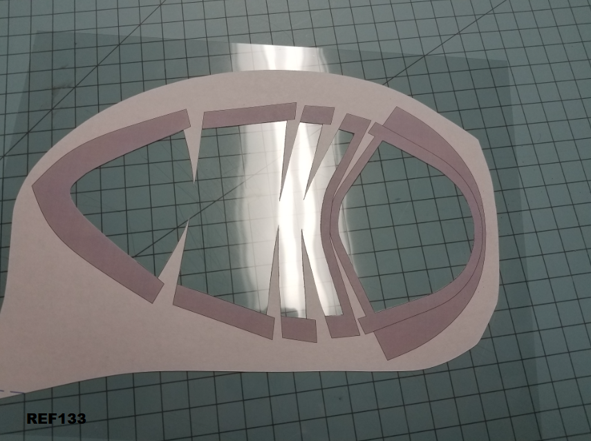
Use spray adhesive on the back side of the paper, let it tack up a bit, then carefully lay on top of an overhead transparency or other form of flexible plastic sheet.

REF133
WonwLQp.png


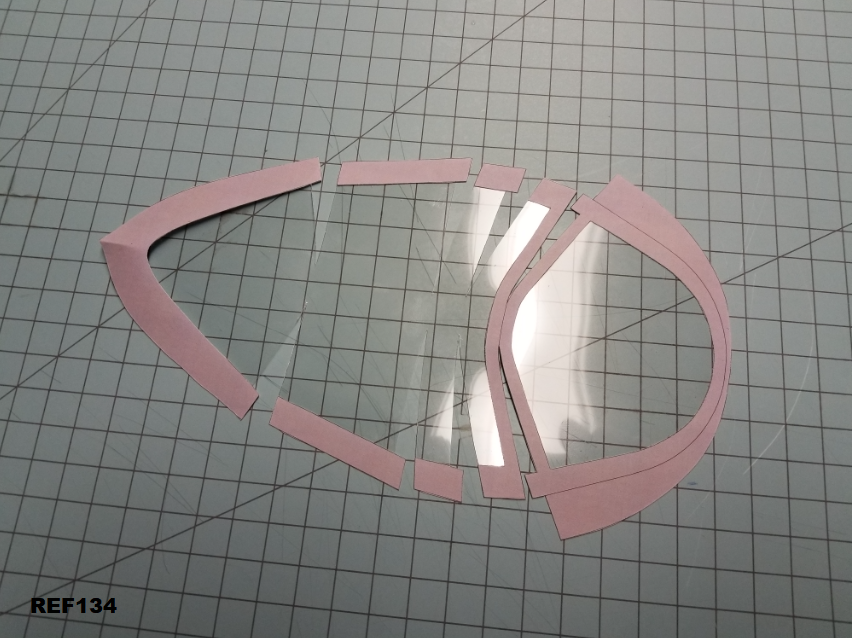
Once the glue has dried (give it at least 5 minutes), cut off the excess.

You can also see I've added a slight crease to the back point to help it along as we glue it up.

REF134
PwIH8qw.png


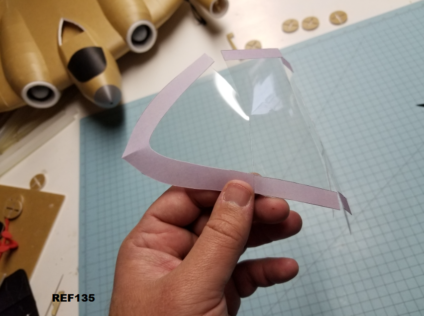
Glue one tab at a time. It only takes a small drop of hot glue. I like to make sure the tabs are on the back side, it looks cleaner. Laser overhead transparencies work best. They're designed to have hot toner stick to them, so hot glue bonds quite well with no prep. Watch the stringing from the hot glue though, the strings like to really stick, and no one likes a dirty windshield. :D

REF135
IqTnSLI.png


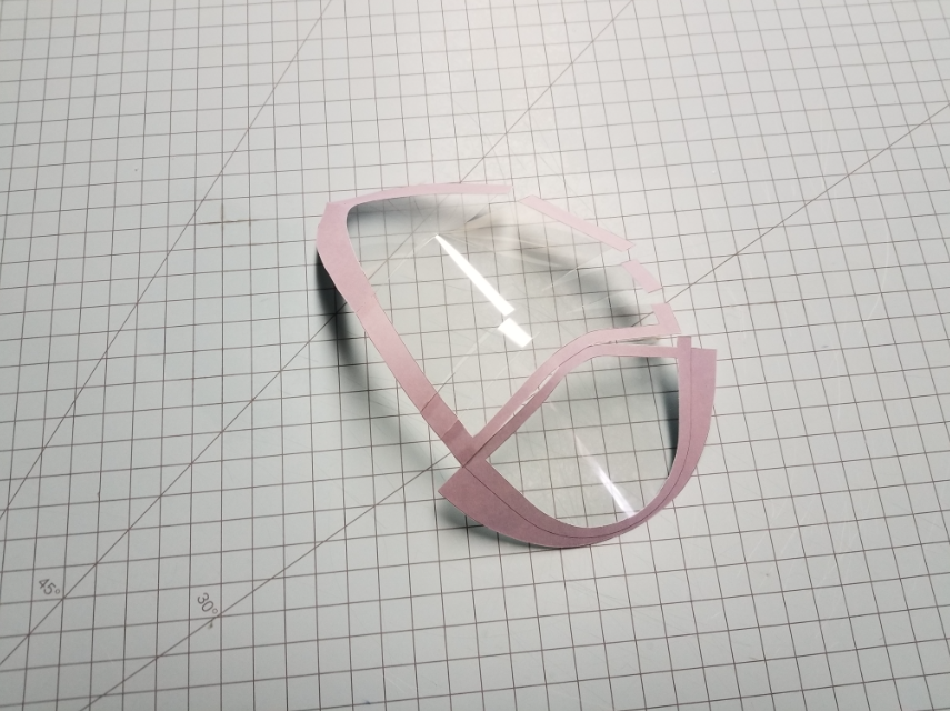
Do one complete side, then the other.

REF136
cWl0zpL.png


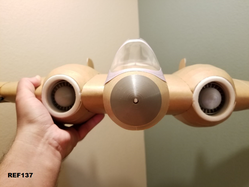
Then glue it onto the cockpit. I like to only add glue in three places. A couple drops right at the back point, and then a couple drops on each side where the overlap is the thickest. This way, it will stay attached in flight, but generally pops right off if you "land" in a tree or something. It's easy to re-attach.

REF137
9shXkLT.png


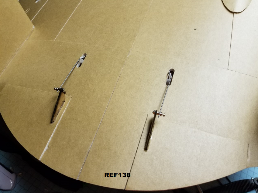
I'd imagine if you're building this plane, you probably have a preferred servo horn and pushrod arrangement. I like this method. Simple, and it just works. I've included gauges for Reflex, as well as control throws for both elevator and aileron control. Best setup method for this plane is quad elevon. Essentially, every control surface should do both elevator, and aileron.

REF138
GP0xAQi.png


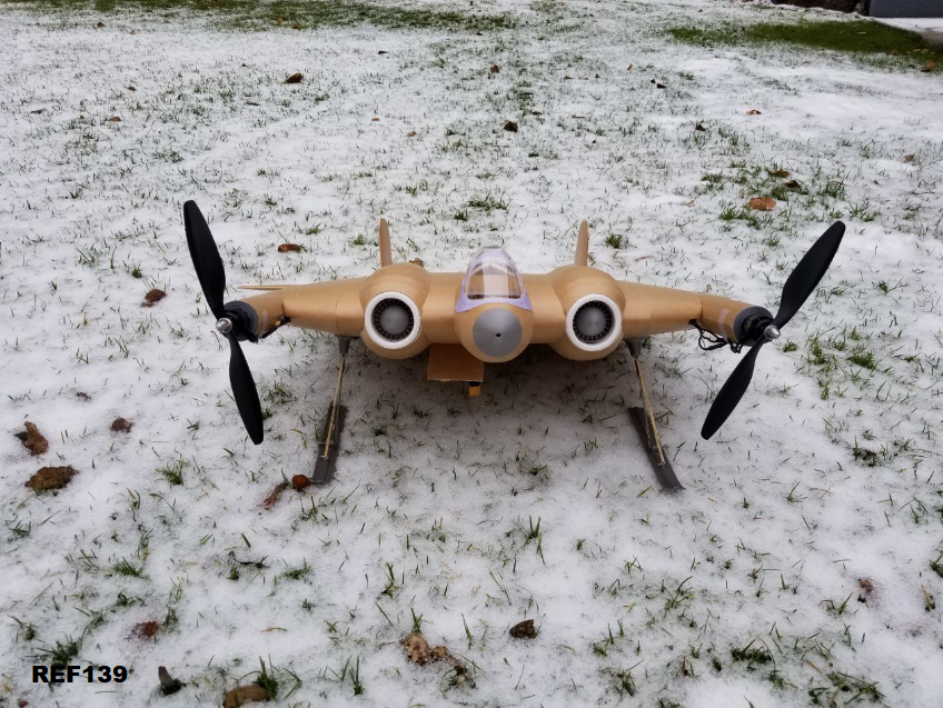
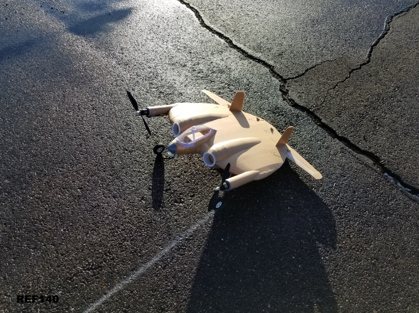
Didn't have a lot of time to get too fancy with landing gear, but I do have a 3D printable tailwheel that can be servo controlled, and some 3D printable mounts that take a 2-3mm ish landing gear wire. I used the same mounts to attach both skis and wheels. I'll upload files for the skis as well. The tailwheel is probably only needed if you want to pretty up the plane, or if you don't use any differential thrust. With diff thrust you could probably use a brick for a rear skid and still turn lol.

REF139
mGkS21n.png

REF140
pzAKjDA.png


And that's pretty much. I'll be happy to answer any build questions you might have. More refinements may come to this guide in the future, but I think I covered pretty much most of it.
 

rockyboy

Skill Collector
Mentor
Awesome job guys!! I really want to see other builders take on this project - it looks amazing and the plans are a work of art. :applause:
 

MojoIron

New member
Build Guide?

Hey LocalFriend,

Tim Van Heerden here, I'm going to start on this next week most likely. It'll take a while as we don't get decent foamboard in South Africa so I make my own.

Any chance that you (or the Sponz :D) have a build log or guide? If not it's cool, I'll try to figure it out.

Thanks again guys, I've loved this plane since the first time I saw it, if only it had been conceived 5 years earlier, I can only begin to imagine what aircraft might look like today.
 

localfiend

I like 3D printers...
Mentor
Hey LocalFriend,

Tim Van Heerden here, I'm going to start on this next week most likely. It'll take a while as we don't get decent foamboard in South Africa so I make my own.

Any chance that you (or the Sponz :D) have a build log or guide? If not it's cool, I'll try to figure it out.

Thanks again guys, I've loved this plane since the first time I saw it, if only it had been conceived 5 years earlier, I can only begin to imagine what aircraft might look like today.

Heh, yeah there's a build guide. :D Go back a few pages in this thread. Starting page 7 there's a build log. It's 140 images with captions. Maybe I should make a reference to that in the first post.

It takes me 6 sheets of foamboard to cut out on my CNC. Might be a little more than that by hand. Good news is that if you're making your own, you really only need to add paper to one side for the majority of the parts.
 

localfiend

I like 3D printers...
Mentor
Just started playing with landing gear in Fusion360. I plan to make it easily 3D printable and lightweight. Tires will be done in flexible TPU filament.

XF5U Landing Gear2.png

The actual landing gear was telescopic. Don't think I can do that at this scale easily. Of course, super tall gear won't be needed if you don't have 17" props, so the gear should fit in the body normally.
 

MojoIron

New member
Heh, yeah there's a build guide. :D Go back a few pages in this thread. Starting page 7 there's a build log. It's 140 images with captions. Maybe I should make a reference to that in the first post.

It takes me 6 sheets of foamboard to cut out on my CNC. Might be a little more than that by hand. Good news is that if you're making your own, you really only need to add paper to one side for the majority of the parts.

Thank you!! Can't wait to start on this, might make your Gladiator first though... :)
 

localfiend

I like 3D printers...
Mentor
Thank you!! Can't wait to start on this, might make your Gladiator first though... :)

The Gladiator is a fun plane. Good place to start out if you're not used to paper on foamboard builds. It's just a little bit more complicated than standard FT designs.
 

Daniel Kezar

Ultimate Cheap Skate
Awesome job guys!! I really want to see other builders take on this project - it looks amazing and the plans are a work of art. :applause:

i plan on building it. probably not flying it for fear of ruining its beauty and lack of electronics.

also, in response to the last statement, true dat! true dat!