FTFC19 Colonial Viper mkII, designed by ThreePistons

ThreePistons

New member
After a year and a half of scratch building dtfb planes, it's time for me to finally try to design my own! And am I going to build an easy plane like a Cessna or top-wing trainer? No, of course not. For my first original design I'll be attempting to recreate the mkII Colonial Viper from Battlestar Galactica. Also there is a self imposed time limit as I wish to join the Flite Test Forums Challenge 2019... Let's see how this goes.


Vipermk2ByLukasStratmann.jpg


Picture source: http://lukasstratmann.com/colonial-viper-mk-ii-battlestar-galactica/
 
Last edited:

ThreePistons

New member
As of the posting of this thread I have already done some work on my viper, so this first build log will bring you up to speed on what has happened so far.

The plan is too build a mkII Colonial Viper from Battlestar Galactica, from scratch, in two weeks. The scale is currently 1/12, which will result in a model approximately 27 inches long. My power setup is currently up in the air, but I have a spare C-pack motor as well as a redbottom motor with 20amp esc that could be used, although I doubt either of these are the right size and I will probably have to acquire a new motor/esc for this plane. The motor will most likely be at the rear of the plane in a pusher configuration, and I may have to add canards to the nose although I would prefer to avoid that.

My prototype model uses FlyingPenguinRC's fold'n'form technique, which he explains in his recent article [SPOILER="here"]https://www.flitetest.com/articles/fp-mustang-fold-form-flying-penguin-rc[/SPOILER]. The concept behind fold'n'form is making loops of dtfb by removing the paper on one side and then fitting formers in either end giving the segment shape. Multiple of these formers are then stacked together to give the plane's body it's shape.

I started by downloading this lovely free 3d model from CGTrader [SPOILER="link here"]http://lukasstratmann.com/colonial-viper-mk-ii-battlestar-galactica/[/SPOILER] and loading it into blender. There I chopped the model into segments and UV mapped both the skin segments and the shapes of the ends of each skin segment. I then exported the UVs as a png and resized/printed them in photoshop.
View attachment 114561 3d model in blender along with formers, skin, and UVs.
I didn't think of documenting the prototype body's build, but here is a picture of the completed prototype body with cockpit:
IMG_1230.JPG IMG_1231.JPG

Ok, that was two pictures. And no, this is not what I intend for this to look like, v2 was started almost immediately after the body's completion. The issue with the body is that it ended up too round. To remedy that v2 will use formers that are much more square as well as score cuts opened up with bbq skewers on the skin, which will result in a more boxy, but (hopefully) a much more recognizable, look!

If you look you can also see the engines in the background, which turned out much better than the body did.

The next update will probably come tomorrow, with the prototype v2 creation and plans.
 

Attachments

  • blenderModelv1.PNG
    blenderModelv1.PNG
    321.7 KB · Views: 0

ThreePistons

New member
For prototype v2 instead of using the 3d model to created the plans directly I used it to make a much lower polygon version of the viper (seen below in the large picture) which I printed out, cut, traced, and cut again.

blenderModelv2.PNG


On the v1 viper the formers had enough polygons that I could just cut the corners without rounding them off very much, however the v2's the body (and thus its formers) only have 8 sided, as apposed to 16 on the v1. But instead of rounding out all of the corners, I only rounded of the corners on the 4 sides, leaving the corners sharp on the 4 corners. The idea of leaving the corners sharp is to give the v2's body more shape than the v1's, but just that is not enough to give the body it's shape and so I made 50% cuts down the skin from a corner on one former to the matching corner on the next former, which I then ran a bbq skewer through (before I removed the paper). These creases made it so there are distinct edges only on the 4 corners, while still having curved sides, just like my reference photos! (which I haven't bothered to show yet but are at the bottom of this post) Pictures describing the construction of a body segment are located below.

IMG_1232.JPG IMG_1233.JPG IMG_1234.JPG IMG_1235.JPG IMG_1236.JPG IMG_1237.JPG IMG_1238.JPG IMG_1239.JPG IMG_1240.JPG IMG_1241.JPG IMG_1242.JPG IMG_1243.JPG IMG_1244.JPG

Some glamour shots of the v2 body with cockpit and under slung intake installed:

IMG_1245.JPG

IMG_1246.JPG IMG_1247.JPG

Reference photos:

300px-Viper_Mk_II_orthos.jpg BG_Viper MkII schematic1.jpg viper_markii660.jpg Vipermk2ByLukasStratmann.jpg viper-mk-ii-04.jpg


Next update sometime.
 

ThreePistons

New member
ENGINES!

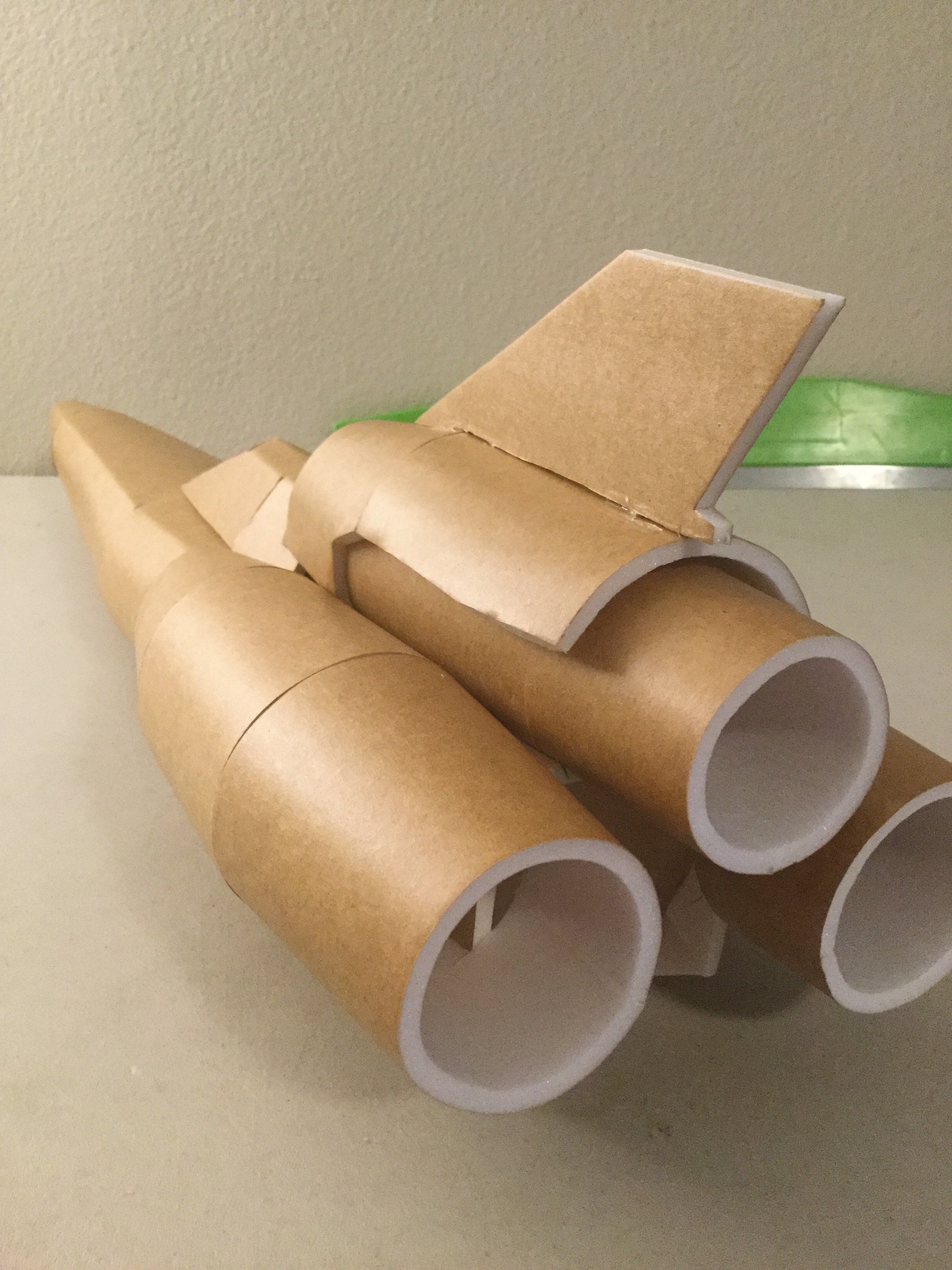
The three engines are made out of foam board wrapped into conical sections, and then glued together. The side engines are made of two circle-circle segments and one circle-oval segment (AKA the front of the engines are ovals, not circles). After forming the engines sections are cut away letting the round engines to meet up with the square body. The reference lines for the cuts are on the engine plans and are marked with pencil and ruler before folding (or after, if you want).

The cowling over the upper engine is made of two pieces. The first one has a former that is pressed against the upper engine and has an arch cut out, allowing for some airflow. The front tips of the first piece are bevel cut so they can be glued onto the canopy. The rear piece has no former but is glued to the front piece and there is a thin piece of foam glued to the canopy and engine gives it and the vertical stabilizer support.

Here on the prototype model the two side engines are nowhere near symmetrical but that will be remedied in the final version, which will have reference marks on the body.

The motor will be mounted on the flat plate on the back of the body, and there will be extra bracing on the interior. The bottom the rear body will become a hatch, supported by bbq skewer hinges, allowing the battery to be swapped out. Because of the complex shape of the wings they will use a KF airfoil, but I haven't yet decided how I am going to attach them.

IMG_1250.JPG
IMG_1251.JPG
IMG_1249.JPG IMG_1252.JPG IMG_1253.JPG
 

FoamyDM

Building Fool-Flying Noob
Moderator
just beautiful. Great body work. Question is will there be enough lift? or will you do a front mount, and nutball it?