FTFC23: Build-ruary by Inq: Inq'd Focke Wulf Ta 152H

Inq

Elite member
This is one I've wanted to do for some time totally in a 3D print. Until, I get to the point where I fly more than I crash, I've held off. But... for FTFC23, I think a foam version will be a great start start and transition... especially if it is BIG = 95 inch wingspan.

As of the firing gun, this is all I have... my references and a motor and a thought to do a 1/6th scale version.
PXL_20230201_112638093.jpg


Back to Inq's top level Build-ruary...
 
Last edited:

Inq

Elite member
Found some decent drawings on the Internet. Here I've sucked them into CAD so I can start generating the pieces. I haven't decided whether to do more standard, box outline FT design or more Master Series design techniques.
Ta152H 6th Scale.png


The fun begins...
 

Bo123

Elite member
This is one I've wanted to do for some time totally in a 3D print. Until, I get to the point where I fly more than I crash, I've held off. But... for FTFC23, I think a foam version will be a great start start and transition... especially if it is BIG = 95 inch wingspan.

As of the firing gun, this is all I have... my references and a motor and a thought to do a 1/6th scale version.
View attachment 234289

Back to Inq's top level Build-ruary...
what size motor is that? I doubt that it could power a 96" plane tbh.
 

Inq

Elite member

Bo123

Elite member

Inq

Elite member
I'm kind of doubting this is going to be done in February for FTFC23. I have way too many firsts for me. This will be my first attempt at using some Master Class techniques of bending foamboard. I also want to try some things and I haven't even designed it yet.

I do have a first cut on the CAD for the wings and analyzed a minimum weight spar. Although I maybe being overly optimistic, I still have hopes of keeping the structural (and cosmetic) weight down to about a kilogram before components.

I want this to be pretty close to scale... including blisters, guns, antennas. I want to put an active pitot tube on it for getting airspeed, but I won't go so far as to model seems, bolt heads and such. I plan on using the actual airfoil for the FW-190 (NACA 23015.3).

I was thinking about trying to fully hide servo control horns. Elevator is easy, rudder... a little more trouble, but the ailerons are the hardest. Shirly someone has tried this, but I'm wondering if anyone here has and whether there are any pitfalls, I'm missing. The servo and horn are entirely inside the wing at neutral and full deflections. I used the recommended aileron deflection of 12° of the FT MS Spitfire. With that, I get a minimum force multiplier on the control surface of 3.6x. Here, it is shown at the maximum aileron deflection of 12°.

ServoLever.png
 

Inq

Elite member
Today's progress...

Finished the CAD work on the wings. I'm attempting to use the actual airfoil of the airplane (NACA 23015.3) and even going to try and incorporate the 3° Washout that the actual plane had between the root and the start of the aileron. IOW, the root has an AOA of 3° and the rib just before the aileron has a 0° AOA. The rest of the wing to the wingtip has a constant 0° AOA.
Ta152H 6th Scale.png


The current plans are to make it a 3 piece wing since the total is ~94" and using the baseline DTFB. The center 30" (red) will be one piece, with outer wings 30" (green) and the wingtips 2.24" (blue) will be done in ABS on the 3D Printer. I'll create jigs using 3D prints to hold the wing while spars and ribs are place and the glue sets... hopefully holding the 3° of Washout.

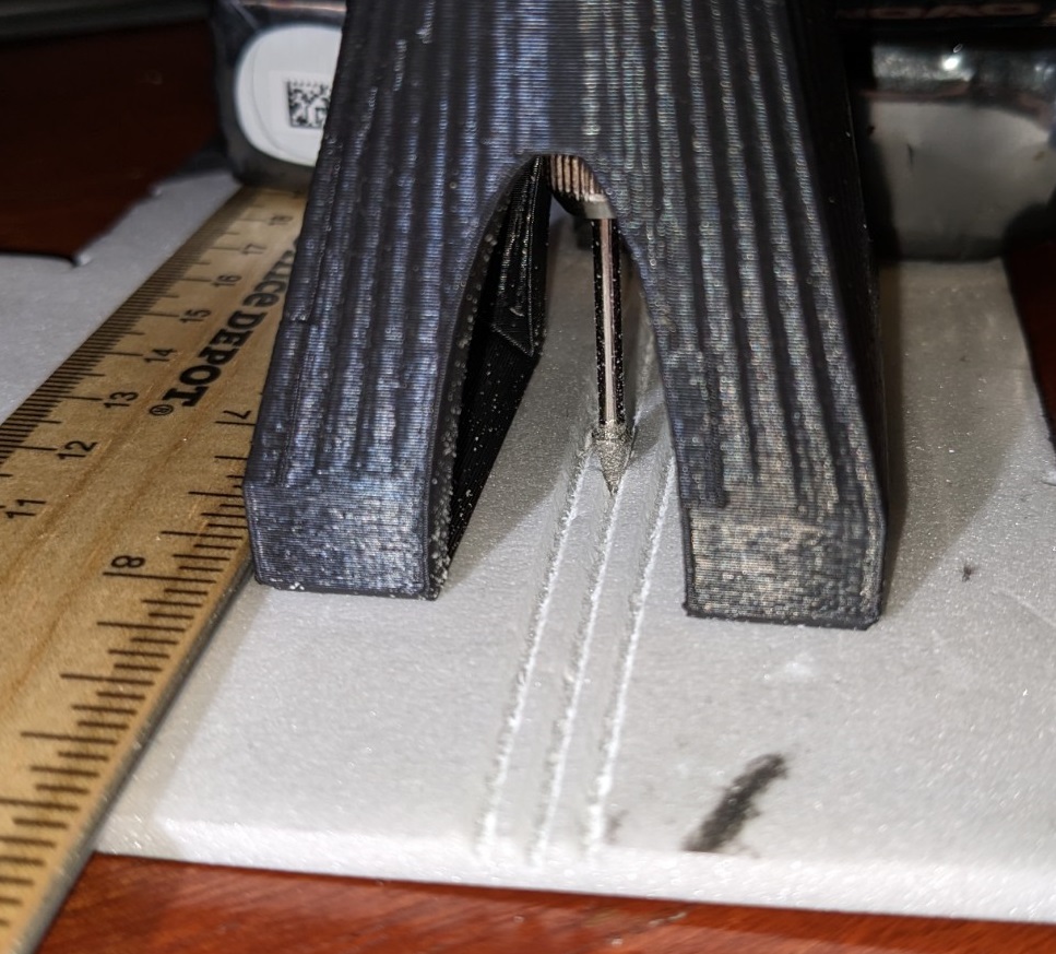
I've created another tool (InqRouter) that is waiting to be approved in the resources to make the cheap Harbor Freight rotary tool into a mini router... perfect for cutting grooves in the foam board to help curvature at the leading edge. It's an experiment, and I have no clue if it'll work, but stay tuned for the success or the crash and burn.

435641_c49413aa16635722691546705db12338.jpg


About the only progress besides design/CADing/building/testing of InqRouter was to print out one of the wingtips to see if I have settings right.

One wingtip is 9.7 grams.
PXL_20230211_014248669.jpg
 

Inq

Elite member
Sooooo is it 3d printed or foam?

The wingtip above is 3D Printed. The other 90 inches of span will mainly be DTFB. The FW is nice that way... doesn't have all the 3D curves of the Spitfire. I haven't got to the expert level of doing 3D carving on balsa / Depron. If I have to make something with 3D curvature, I'll always turn to the 3D printer. The idea of trying to hand carve two wing tips and they even are remotely confused as being mirror image of each other is simply laughable :ROFLMAO:. With the 3D Printer, I hit one button and poof... mirror image. Crack one up in a landing... hit one button... print another. I gonge up a Depron wingtip... and spend hours weeping and whittling a new one :cry:.
 

Tench745

Master member
I have used a similar router base on my Dremel with a carbide burr to make channels in foam for running wires, spars, recessing servo covers, etc. Works quite well. Never used it to help curve the foam though. It's an interesting concept.
I took a look at the polars for the 23015.3 airfoil. I didn't do any of the math or anything, but at first glance it looks like a decent choice for an RC-sized wing. Sounds like you've got a good start on a complex build.
 
  • Like
Reactions: Inq

Inq

Elite member
I took a look at the polars for the 23015.3 airfoil.

I'd like to be able to take credit, but it was Kurt Tank's actual airfoil used on the airplane at the root. The wing tip is a 23009, with 3 degrees of washout. The Reynold's number should be cruising around 400K and near 1M at top end. Just checked the Polar and it has quite a docile stall characteristic.