Getting SOOOOO close.....

Turbojoe

Elite member
I keep plugging away at trying to get the perfect print. It seems once a week I find another tidbit out there that gets me just a little closer. A while back I designed and 3D printed holders for my digital "dial" indicator and got E extrusion and X, Y and Z steppers and bed level set down to a gnats ass so they are not the issue. My only problem always has been and still is getting printed hole size to match my .stl design size. I know it's possible. I've seen tons of videos with people showing their parts that fit together properly. They just never tell the entire story of how.......

I've been using Cura since day one. Out of frustration I've been trying Slic3r for the last week or so. Not at all impressed. Really crappy prints and even worse hole sizes so I uninstalled it. It just so happened that when I fired up Cura again there was an update to 4.6. Now I'm back to better looking prints BUT still have the hole size issue. I've been playing with horizontal expansion in the "shell" section and that has made the single largest improvement. After trying all kinds of settings I've settled on 0.15 mm compensation. There's gotta be some other minor adjustment somewhere that I don't know enough about to set properly and it's driving me bonkers. If I can get it this close consistently I'm not willing to settle for "close enough". I want it right on the money so if I spend the time to create something that has to fit into something I didn't create I want it to fit.......

Here's my situation: a very basic test piece created in TinkerCad. 14 mm square by 3mm thick with a 6 mm hole in the center. Consistent printed outcome using fresh Hatchbox black PLA is 14.20 mm on X AND Y axis. Consistent 2.90 mm on Z axis and the center hole is consistent at 5.80 mm. So close yet so far away. I know there is some tiny Cura compensation that I haven't learned. ANY suggestions from one of you Cura Guru's would be truly appreciated!

I'm attaching my file in case someone wants to test it.

Joe
 

Attachments

  • Test 14x3x6.stl
    4.8 KB · Views: 0

CapnBry

Elite member
I will say that interior holes like that are never going to come out the right size. For starters, if you look at the STL you don't have a 6mm circle you have an approximation of a circle with 19 segments, so between each of those 19 points, the hole is going to be smaller because the segment cuts off the arc with a straight line. Couple that with the fact that the filament has width, it isn't infinitely thin, and therefore you have less material on the outer edge of the extrusion with more material on the inner edge of the extrusion because the inner path is shorter than the outer path. Because of that the material can sorta bunch up or ooze into the center and make the printed hole smaller. Even a 0.5mm extrusion width is 16.6% the diameter of the circle that's being printed so there's a significant amount of error at that ratio.

What is accepted practice for interior holes is to make them oversized in the model to account for the number of segments and the inaccuracy of laying down a wide swath of plastic in a small circle. You'll find a number that works great for each hole size and extrusion width and that just becomes your hole size. Like my M3 for things I want the screw to bite into is 3.3-3.4mm (PLA vs ABS), if I want it to pass through (a 'clearance hole') then that is 3.6mm, if I am tapping it, I will do 3.2mm and make sure there are plenty of perimeters to cut into. At M5, I can get away with a 5.4mm hole for a clearance hole. Note that I needed 0.6mm at 3mm and only 0.4mm at 5mm due to the extrusion width being less of a percentage of the finished hole size. Also note that the first 5-10mm of a hole will almost certainly be smaller due to elephant's foot effects on the build plate.

Your part coming out very slightly larger than expected tends to be an over-extrusion issue. Make sure that when you calibrated E-steps that you ran a lot of filament through at a very low speed, like 300mm at F100. I find that just running 100mm or 50mm and trying to measure that to sub-millimeter accuracy is pretty tough and at 300mm even a 1mm error is just 0.3% extrusion error. Running the E-steps test at fast speed can also cause less material to come out, even if you don't hear the motor miss steps, so be sure to run it at a painfully slow speed to make sure you're not compensating for that loss in E-steps that will end up as over-extrusion in a finished print. You can also weigh the finished part to verify that the amount of extrusion the slicer tried to put in it ended up in the print, but that really only works out for larger parts.

EDIT: Just printed your STL on my printer and I get 14.00mm if I only measure the top half, but 14.2mm if I measure the entire part so I could use a little more compensation or less squish (actually i know it to be the latter, I need to relevel my bed). The hole is 5.80-5.88mm depending on if I am measuring across one of the flats or between two of the points of the "circle". I would say your printer is pretty dialed in if you're measuring the whole part, or might be slightly fatter at the bottom and because the part is so short (in Z) it doesn't get a chance to get down to actual dimension while recovering from elephant foot which can take 5mm or more.
 
Last edited:

Turbojoe

Elite member
Tons of great helpful info. MANY thanks!

If I read this right TinkerCad and its method of rendering a hole is likely MY biggest problem? If so I can accept that now that you pointed out that the hole is not actually a true round hole.

I spent two full days tearing down and rebuilding the Ender 3 ensuring every angle was exactly 90 degrees, rollers and belts were adjusted to optimum and measuring and uploading extrusion and stepper travel g codes. There are so many videos out there of guys showing exact fit of 3D printed parts. Could it be that designing those parts with a high end CAD program is how they achieve that level of precision? I know my printer is mechanically optimized. Now I need to optimize the way I create, compensate and print items.

I like your approach to measuring extrusion. Because all of my printed measurements are consistent I'll bet I'll find some over extrusion using your method of measurement. I'll have to give it a try maybe this weekend.

Joe
 

CapnBry

Elite member
If I read this right TinkerCad and its method of rendering a hole is likely MY biggest problem?
All CAD programs do this. Fusion360 does it on export as part of the "mesh resolution" option or something like that, OpenSCAD you specify it per hole, etc. This is because the STL format doesn't have a command for "circle" or "arc". It ONLY can make triangles, so any curves are exported as hexagons, septagons, octagons, and on down to 19-agons in your 6mm hole or many more for bigger holes.

When the slicer then generates a hole to gcode, it offsets the circumference by 1/2 the extrusion width and brushes off its hands and says "EXACT DIMENSIONS", which works fine for external, straight perimeters, but in the case of a curve, the inside radius plastic will bunch up and squeeze into your hole a bit, and the outside radius will spread thin and be microscopically under-thickness (in Z). The smaller the extrusion width and the larger the hole the less this has an effect but is unavoidable because we're not drawing infinitely thin lines we're taking a ribbon [of plastic] and trying to bend it around a circle.

So both of these have an effect that is unavoidable so we've all built test pieces with different hole sizes, large enough to get away from bed squish and the XY edges, and just design all our parts with holes that give us the final size we desire, knowing that the model's holes will be slightly larger than the finished print holes.
 

Turbojoe

Elite member
You are obviously CAD savvy. Thanks to your explanations it's starting to kinda/sorta make a little more sense to me. I've been a Jet Engine (Navy) and auto/freight moving equipment technician up until retirement last year. To me dimensions input MUST produce dimensions output or very expensive parts fail and in the case of aircraft lives are in jeopardy. It's becoming obvious that it's a whole different and much less critical ball game with 3D printing. That's OK. With input like you've been giving I now have a better direction to follow. I just need to somehow learn to accept the fact that exact is not really exact anymore. LOL.

Joe
 

CapnBry

Elite member
hehe yeah it is true it is a different ballgame and takes a little getting used to designing parts for 3D printing. The nice thing is that when a machine is dialed in, it is consistent, and you'll get the same result every time give then same input gcode. The smaller holes issue is something that even Prusa talked a lot about at the onset and proposed the "polyhole" concept which was a way of trying to calculate the exact number of faces and extra size added to a hole's point-to-point dimension to have it come out the size you want. It wasn't really able to be generalized to all hole sizes and extrusion widths though, so the whole world just decided to determine a known value that gives you what you want and just always use that. You'll always get the right size so that's great for building an assembly, you just need to know what that size is for every hole diameter and what fit you want.

The expansion of the part near the print bed is something that's always a bit of an issue though. It can only be alleviated by exact first layer height and if the slicer supports some sort of dimension reduction for the first layer. It is really hard to file down the base to get it to size so it is best to try to get this right or avoid mating surfaces that need to be exactly flush if that 0.1mm or so is going to throw it off.

The Z height can always a problem too, because we print layer by layer so if you want a 15.70mm high part and you have 0.15mm layers, you can only get 15.60mm or 15.75mm. This is something that usually is not compensated for in the model, but rather is done by selecting a layer height that the Z dimension is a multiple of. That's obviously not possible for a design that's not all one height, so many slicers can do variable layer height so you can lower the layer height near the tops of things and get a closer final height. Just keep in mind that you'll likely have layerheight / 4 of error on average or layerheight / 4 max in the Z dimension, and parts tend to come out a liiiiiiittle bit shorter than you'd expect due to the first layer squish.

Finally, square corners always have a bit of rounding to them which is proportional to the extrusion width. That's usually only a problem with small interior squares (which are just 4-sided circles :LOL:) so those may need either cleanup with a file in the corners or to make the dimension slightly larger, which means your corners will touch but the flats might have a few microns of gap.

The best part is that 3D printed parts are generally cheap to produce, so you produce a part, see what fits and what doesn't and tweak the model slightly and give it another go! Contrast that to what you're used to where you can send off the exact dimensions you want and expect the part to come back with those exact dimensions, but it was expensive and took a long time. You wouldn't want to send out plans for a part and have to go through 3 or 4 iterations with that long lead time, but with 3D printing you just quickly tweak it to come out the perfect dimensions in the end and hit print again.
 
Last edited:

quorneng

Master member
I have found getting printed things to 'fit' in engineering terms is really a case of 'suck it and see'.
About the only reliable method is to physically measure the printed dimension accurately and then adjust the CAD dimension by a difference rather than an absolute figure.
To limit waste it may mean printing just a critical part by itself before committing to hours of printing something really complex.
One of the biggest advantages of 3D printing advantage is its repeatability and to make best use of this I have found it pays to break down a structure into individual parts, print them individually and simply glue them together. Of course if this requires many identical parts so much the better. It also means a print failure is less of a disaster.

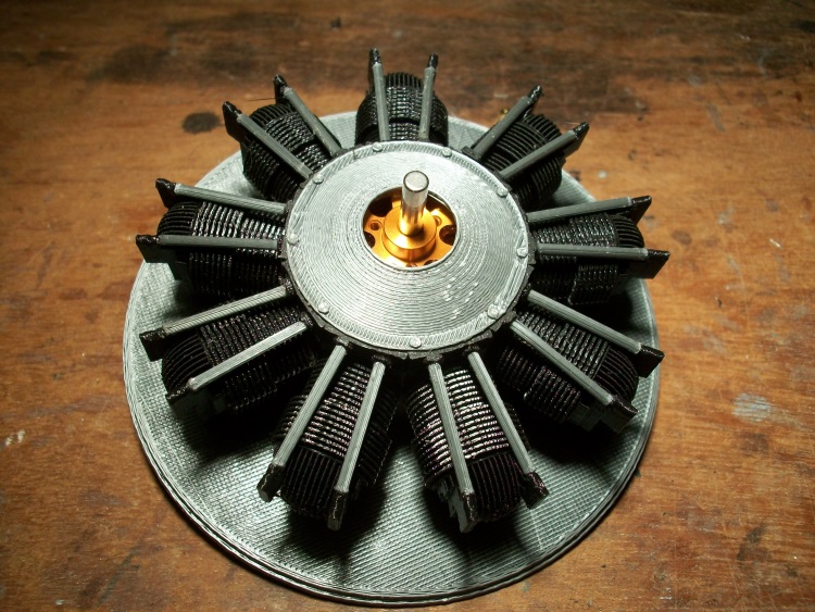
My avatar shows my Antonov AN2. This has a very detailed 9 cylinder radial within the cowling enclosing its electric motor.
ASh-62a.JPG

All 3D printed but assembled from a 'pile' of 56 parts of which there are only 5 different shapes.
 

Turbojoe

Elite member
It looks like my biggest problem is my own stubbornness. I need to accept the fact that we're working with a medium that reacts to temperature differently than metal does. I keep expecting PLA to give me the final print dimensions that I would get with CNC milled metal. It's finally sinking in that I'm not going to achieve that. I played quite a bit with extrusion adjustments yesterday and didn't see any worthwhile improvements so I set it back to the previously meticulously measured E=99.40.

Overall I'm quite happy with my overall print appearance now though I may have to file them here and there and use a drill for the final hole fit. What made me get even more anal about this issue is that I'm now SO repeatedly close to getting what I want and don't know what to adjust. I'm starting to accept that it's likely just the fact that it's the somewhat unstable plastic and it's just not going to happen. I'll just try to avoid things that have holes and things that need to fit into those holes without a lot of work. I don't print doggies and figurines. I come up with ideas that I want to use in building my planes. Sometimes those parts really do need to fit together. It just sucks when two long prints don't fit together even after compensations were made in the .stl. I now need to learn to better compensate........LOL.

Joe
 
Angus from Maker's Muse has some tips on designing holes here:
and a printer tolerance test print here:

But in general you always need to add 0.1-0.3 mm of clearance to your 3D printed parts. It's just the nature of the beast.
 
Trail and error has been the way I have gone about getting holes the right size. The other method is to get it rough then drill it out. Thats quite a good method for motor mounts as the hole makes sure there is material (instead of infill) for the screw to grab, with ought having a too big hole.

I did notice on Cura under Experimental settings there is a small hole feature where its prints using the small feature speed, might be worth a try to make it more accurate...

Jon
www.rc3dprint.com
 

Turbojoe

Elite member
Well I found the secret! Cura 4.6.1 is now out and it has "Horizontal hole expansion" added to the horizontal expansion area in the "Shell" section. That did the trick! After quite a few adjustments and test prints my 14 x 3 x 6 test piece now reads 14 mm on X and Y x 6 mm on hole x 2.90 mm Z height. I'm ecstatic that X,Y and hole are perfect but now I need to learn what I need to change to get that last .10mm of printed Z height. Once I learn that I'll have perfect prints. Any suggestions for what to change that will not affect anything BUT printed Z height?

I still have SO very much to learn and I appreciate all the pointers I've been given here.

Joe