Help me complete my lighting diagram please

Tactical Ex

Senior Member
Got all my gear, now I have to assemble it. But first ... I need to make sure I am wiring this right. If you more experienced pilots and builders could lend me a hand it would be greatly appreciated.

Below is my unfinished diagram (please forgive the MS Paint Graphics, my graphic design applications weren't available at the time of writing this). In an effort to make this an easy of an answer as possible I have put forth 2 options and I believe one of which is the "Correct" answer. You may ask yourself why I have so many terminations and connectors and that is because I am making this lighting system modular and semi-portable so that when I decide to add lights or move it to a new plane it will be relatively easy.

Quick legend:
Yellow Block - XT60
Brown block - 3.5mm Bullet connector
Gray lines - Option 1
Pink and Tan lines - Option 2 (Pink = POS and Tan = NEG)

NightLightChartMulti.jpg

For reference on how this is setup for a single light scenario please refer to this video ...
http://www.youtube.com/watch?v=XjIhyAUzOJU
 

DDSFlyer

Senior Member
So a couple of questions...
First, are you trying to run the 12v LED strips or a 5V system? the 12V will run off of both options that you show (direct off a 3 cell or from a Rx servo lead)
Second, you could probably save some weight and space by going with a JST connector instead of a XT60 for LED lights.
Third, if you have a switch you can run the positive wire through the lights and the negative has to run back to the switch, I believe that's what the HK switch diagram showed, not sure which switch you have either.
It's all personal preference as long as you link it all up and it works, just make sure you don't overload anything and it'll look great
 

Tactical Ex

Senior Member
1. It is a 12v system
2. Good point, I wanted 2 XT60s because I may use the harness for a twin motor setup in the future.
3. This is the switch http://hobbyking.com/hobbyking/store/__46040__Turnigy_Receiver_Controlled_Switch.html. The same one is in the video at the bottom. I'm guessing you mean that option one will work by saying [...]you can run the positive wire through the lights and the negative has to run back to the switch[...]. So the power enters the white lights via the POS wire and exits the White lights via the NEG wire then enters the BLUE LED via the POS wire and exits the light via the NEG wire then completes the circuit via the NEG wire of the y harness to the battery?
 

DDSFlyer

Senior Member
1. It is a 12v system
2. Good point, I wanted 2 XT60s because I may use the harness for a twin motor setup in the future.
3. This is the switch http://hobbyking.com/hobbyking/store/__46040__Turnigy_Receiver_Controlled_Switch.html. The same one is in the video at the bottom. I'm guessing you mean that option one will work by saying [...]you can run the positive wire through the lights and the negative has to run back to the switch[...]. So the power enters the white lights via the POS wire and exits the White lights via the NEG wire then enters the BLUE LED via the POS wire and exits the light via the NEG wire then completes the circuit via the NEG wire of the y harness to the battery?

Yep exactly.
If you are wanting to solder up a breakout wire with two XT60's just add a JST as well to it so that you can still reuse it later down the road. the wires for LED's don't have to be thick (I used some stripped ethernet wiring) so it may be hard to use an XT60 connector anyways.
 

vk2dxn

Senior Member
From what I can see
You have wired in a short between the white led negative and blue led positive. When the switch closes "conducts" it will create a short
 

Tactical Ex

Senior Member
From what I can see
You have wired in a short between the white led negative and blue led positive. When the switch closes "conducts" it will create a short

Does the "short" occur in option 1 or option 2? I didn't think there was a short in either option, I thought the only difference in the options is serial or parallel. I don't think either are "Wrong" but one might be recommended. I am assuming you are referring to option 1, in which case I don't see how option 1 is any different from this ...

http://www.instructables.com/id/LEDs-for-Beginners/step7/Wiring-up-multiple-LEDs-in-series/

... could you clarify?
 

vk2dxn

Senior Member
Does the "short" occur in option 1 or option 2? I didn't think there was a short in either option, I thought the only difference in the options is serial or parallel. I don't think either are "Wrong" but one might be recommended. I am assuming you are referring to option 1, in which case I don't see how option 1 is any different from this ...

http://www.instructables.com/id/LEDs-for-Beginners/step7/Wiring-up-multiple-LEDs-in-series/

... could you clarify?
Sorry mate I just read your post

The first time I saw it I skipped to the diagram to see what you had in mind. Did not realize that you have different configurations on the same diagram "birds nest" lol
 

vk2dxn

Senior Member
I have not read all reply's so I apologize if this has been said already.
I see that your two options are for series or parallel circuits.
The configuration will depend on the voltage of the LED strip's, also does the strip use a bias resistor? If so then you can manipulate the value of the bias resistor to accommodate either series or parallel configuration within reason.
 
Last edited:

Tactical Ex

Senior Member
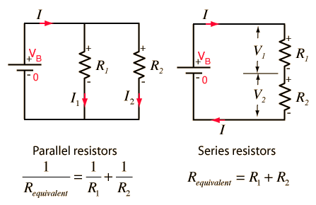
Thanks for taking the time to redraw the diagram William A, that is what I was hoping for. This is a 12v system so is running them in parallel the option that keeps it at 12v per strand? I only realized that one of the options might reduce the voltage to 6v per strand, is that what serial will do?
 

William A

Billy did it....
Thanks for taking the time to redraw the diagram William A, that is what I was hoping for. This is a 12v system so is running them in parallel the option that keeps it at 12v per strand? I only realized that one of the options might reduce the voltage to 6v per strand, is that what serial will do?

Yes,correct. Here's a pic from the net to emphasize.
dcx6.gif


And I'll draw one with LED strips in mind, maybe it'll help.
(BRB)

edited; a redraw turned into more time than I got left for tonite,,, work sucks,,, but I'll leave with this,,, the LED strips them selves are a 'parallel' circuit. One edge positive, other edge negative.

Both 'edges' will give you the supplied voltage 'till' supplier can't keep up.
 
Last edited:

Tactical Ex

Senior Member
No worries, I think you have explained it well enough. I will be wiring according to the second option in my diagram (Parallel). While its a bit more messy wiring wise I'd rather the lights be at the brightness intended at 12v.