Layout sheet

NeroRavencoat1999

New member
Something I've been wondering about with the build plans is if we could have a set of point measurements to make a layout with nothing but a combination square, steel rule, straight edge, compass, and a pen, so this way anyone can build any aircraft even without a printer. All you would need is to work from one reference edge and a reference line on an x y grid to mark points and connect lines to draw out the patterns and the rest is knowing the basic building techniques we all have learned from the videos. I say this because I am a former US Navy aviation structural mechanic and that's how we learn to fabricate components from sheet metal and I don't have a printer, nor do I want to go spend extra money just to get printouts. It's a great skill to learn and fairly easy for anyone to pick up on within the time it takes to do a build.
 

Hai-Lee

Old and Bold RC PILOT
I am Old School and ex military with a strong engineering background. I understand what you are talking about and apart from an old "Conversation" where I tried to teach someone thousands of miles away how to draw plans using some graph paper, a ruler, and a pencil by sending him line end co-ordinates in a string, no one else seems to appreciate the old methodologies.

The strange thing is that the co-ordinate system on input is standard interface on most drafting and CAD softwares. So when plans are drawn the info you are seeking is already coded in the plans when drawn and published.

You also give the inference that you would like the point co-ordinates or similar so that you might draw out your own copies of FT plans. I can print plans or even have them printed full size but then I cannot modify the plans as easy as when I have drawn the plans myself. I have a small library of FT plans and of plans of my own design all hand drawn with co-ordinate information just waiting to be read off!.

If you wish I could tell you how I started translating the screen images to line drawings, (a reasonably quick and painless process ). Alternately I could break down one of my plans for you into a string of co-ordinates if you wish but I would need to know which planes you may be/are interested in and hopefully if I have the plans I could relay the info on one of them. Mind you ALL of my plans have been drawn up as metric so the accuracy of my plans is to within approx +/- 0.5mm of the FT original, (unless scaled of course).

This would take time so I can only offer one set of plans in co-ordinate fashion though!

Let me know!

Have fun!
 

DamoRC

Elite member
Mentor
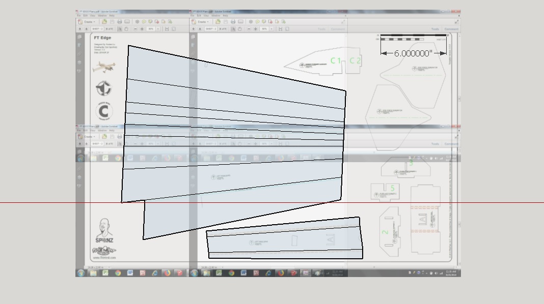
If you have a computer (assuming you have) then you could try to generate these coordinate plans yourself with some free drawing or CAD software such as Sketchup and importing screen captures of the PDF plans. A tedious process, but it works. For example, here is the wing plan for the FT Edge. I have not added the coordinates but that would be just one more step.

Edge Wing Screen Cap.jpg


DamoRC
 

Allenhat

Member
If you have a computer (assuming you have) then you could try to generate these coordinate plans yourself with some free drawing or CAD software such as Sketchup and importing screen captures of the PDF plans. A tedious process, but it works. For example, here is the wing plan for the FT Edge. I have not added the coordinates but that would be just one more step.

View attachment 113097
DamoRC

Sketchup allows you to import one page of the plans at a time then export them as a DXF or SVG that can be opened in Draftsight or inserted into a model in Fusion 360. No need to trace anything.

Each are available for free. Sketchup is open sourced and the other two are available to the hobbiest for no charge.
 

NeroRavencoat1999

New member
If you have a computer (assuming you have) then you could try to generate these coordinate plans yourself with some free drawing or CAD software such as Sketchup and importing screen captures of the PDF plans. A tedious process, but it works. For example, here is the wing plan for the FT Edge. I have not added the coordinates but that would be just one more step.

View attachment 113097

DamoRC
Unfortunately I don't have a confuser
 

DamoRC

Elite member
Mentor
Sketchup allows you to import one page of the plans at a time then export them as a DXF or SVG that can be opened in Draftsight or inserted into a model in Fusion 360. No need to trace anything.

Each are available for free. Sketchup is open sourced and the other two are available to the hobbiest for no charge.

I didn't know I could do the PDF import into Sketchup - do you need a plugin for that?
Unfortunately I don't have a confuser

Funny!:)

DamoRC