Let's make a better FT3D!

rcfred

Member
For version 2 of the tail, I'm moving the rudder hinge back half an inch and moving the horizontal stabilizer forward a quarter inch. After some additional modifications to account for the tapered bottom on the fuse, the rudder ends up looking like this:
IMG_6674.JPG


And the horizontal stabilizer looks like this:
IMG_6720.JPG


Moving the rudder back and the horizontal stabilizer forward makes that V-shaped cutout on the elevator smaller, which should reduce the amount of flex between the two elevator halves.

You may also have noted the curved carbon fiber reinforcement piece in the above photo. I figured, since I had this roll of carbon tow, might as well mold my own reinforcing strips. It took three tries to get to the version in the picture above. On my first try, I cut a slot the elevator and stuffed the dry carbon tow into the slot. The carbon ended up with twists and voids.

On my second try, I made a two-part mold out of some scrap foam and sandwiched the carbon tow between the two parts:
IMG_6687.JPG


IMG_6688.JPG

IMG_6690.JPG


Then I dribbled epoxy onto the exposed edge of the carbon tow.
IMG_6693.JPG


Unfortunately the epoxy didn't penetrate all the way to the other side of the mold.

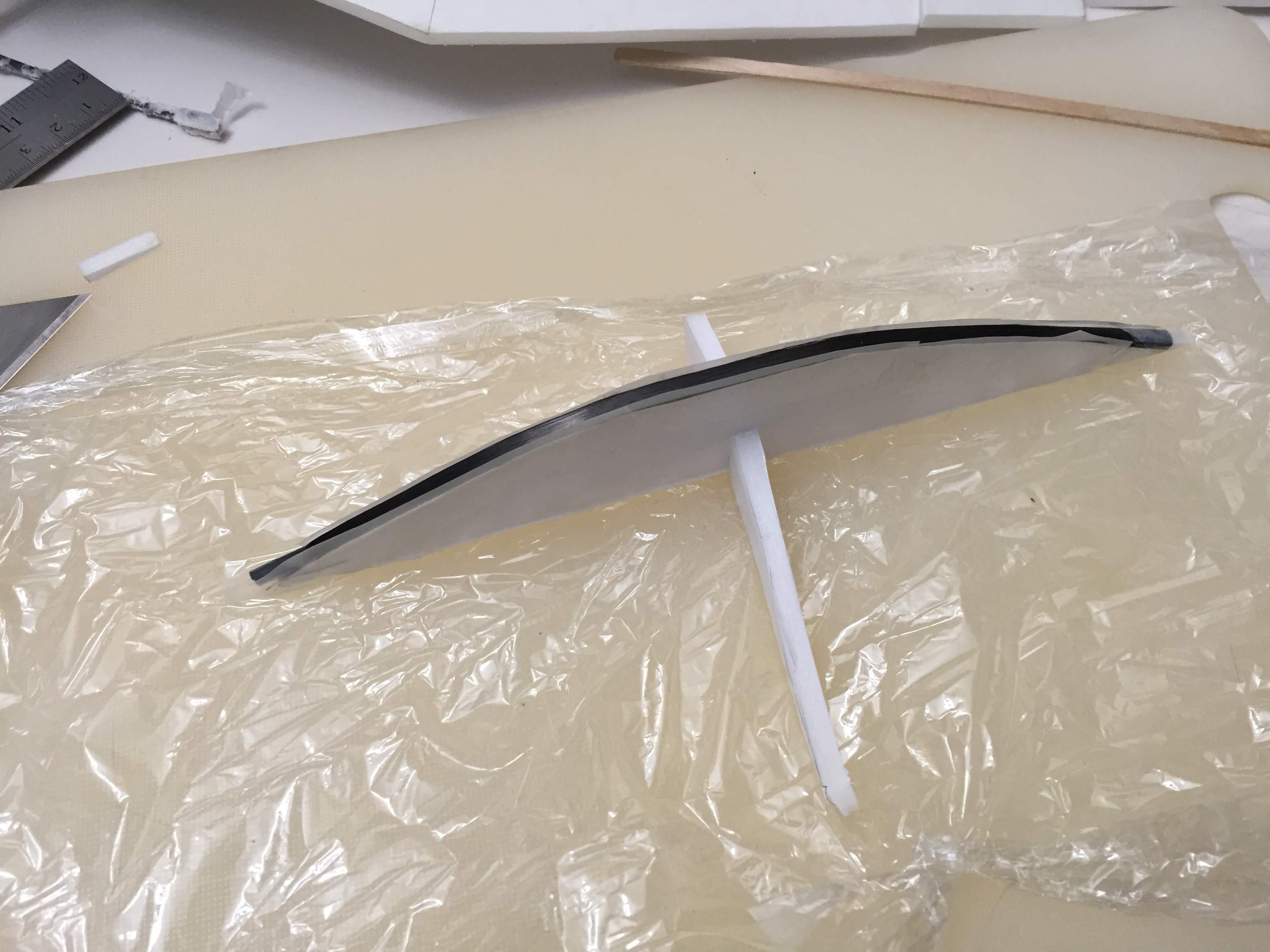
On my third try, I propped up the convex half of the mold with some scrap foam, taped the carbon strip down on top, and applied epoxy directly to the carbon. Then I put the other half of the mold in place until the epoxy partially cured.
IMG_6694.JPG

IMG_6696.JPG


IMG_6698.JPG


After the epoxy had stopped being tacky, I cut the carbon out of the mold, washed away the remaining foam with some acetone, and scraped off the flashing with a razor blade:
IMG_6700.JPG


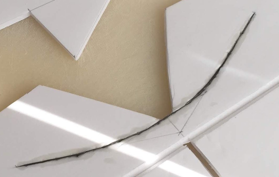
This step left me with a still-flexible curved carbon rod. I cut a slot into the elevator and used some tweezers to push the rod into the slot:
IMG_6701.JPG

IMG_6702.JPG

The process of pushing the flexible carbon down with the tweezers left some dents in the foam along the edge. These dents got smaller once I applied epoxy to lock the carbon in place, but there was still a bit of roughness to the edge of the slot:
IMG_6720 (1).JPG


Next time I'll try letting the epoxy cure completely before inserting the carbon strip.

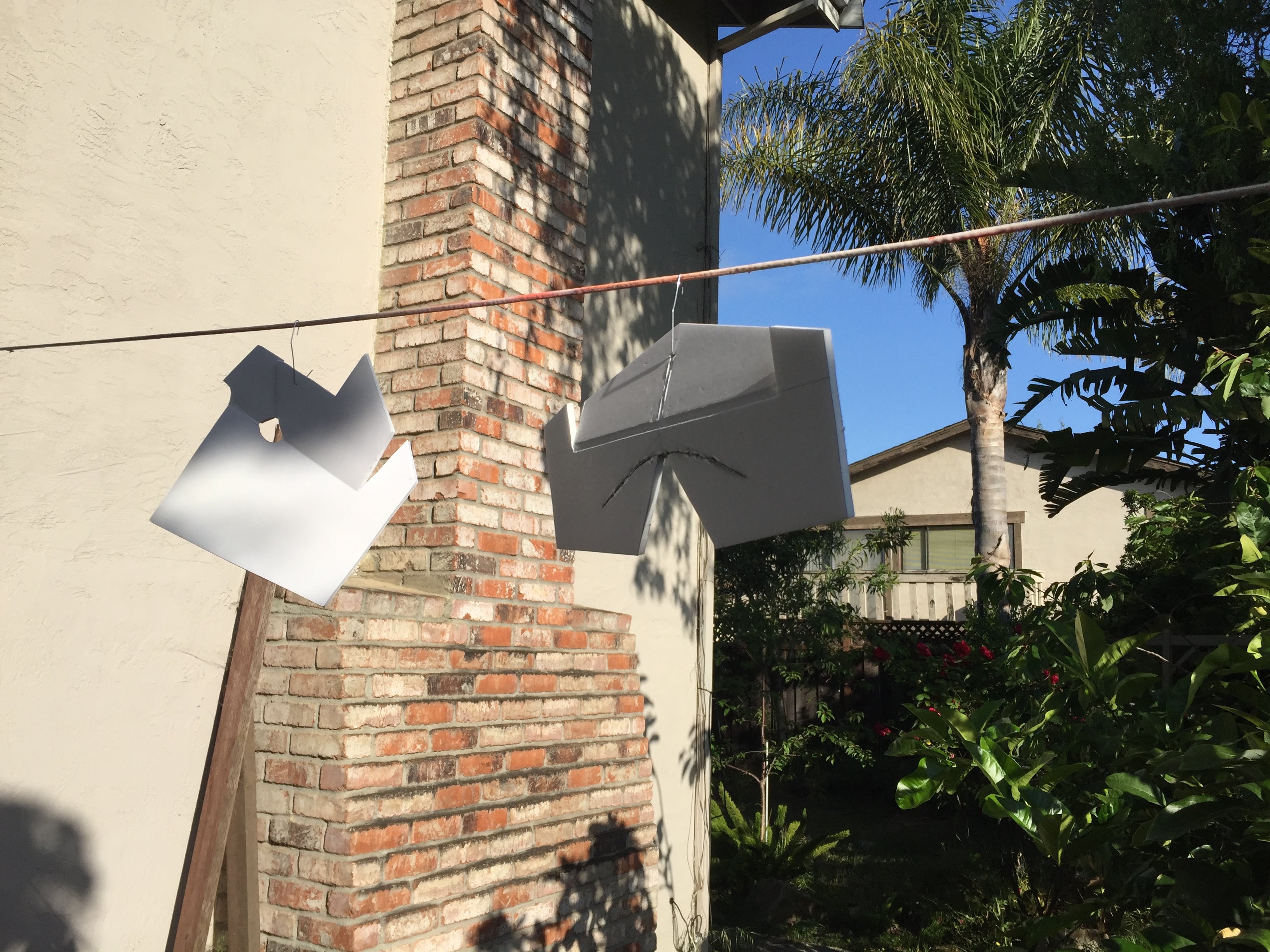
After the reinforcement had set up, it was time for a minimal paint job. I started with a light dusting of white spray paint to seal the paper:
IMG_6721.JPG


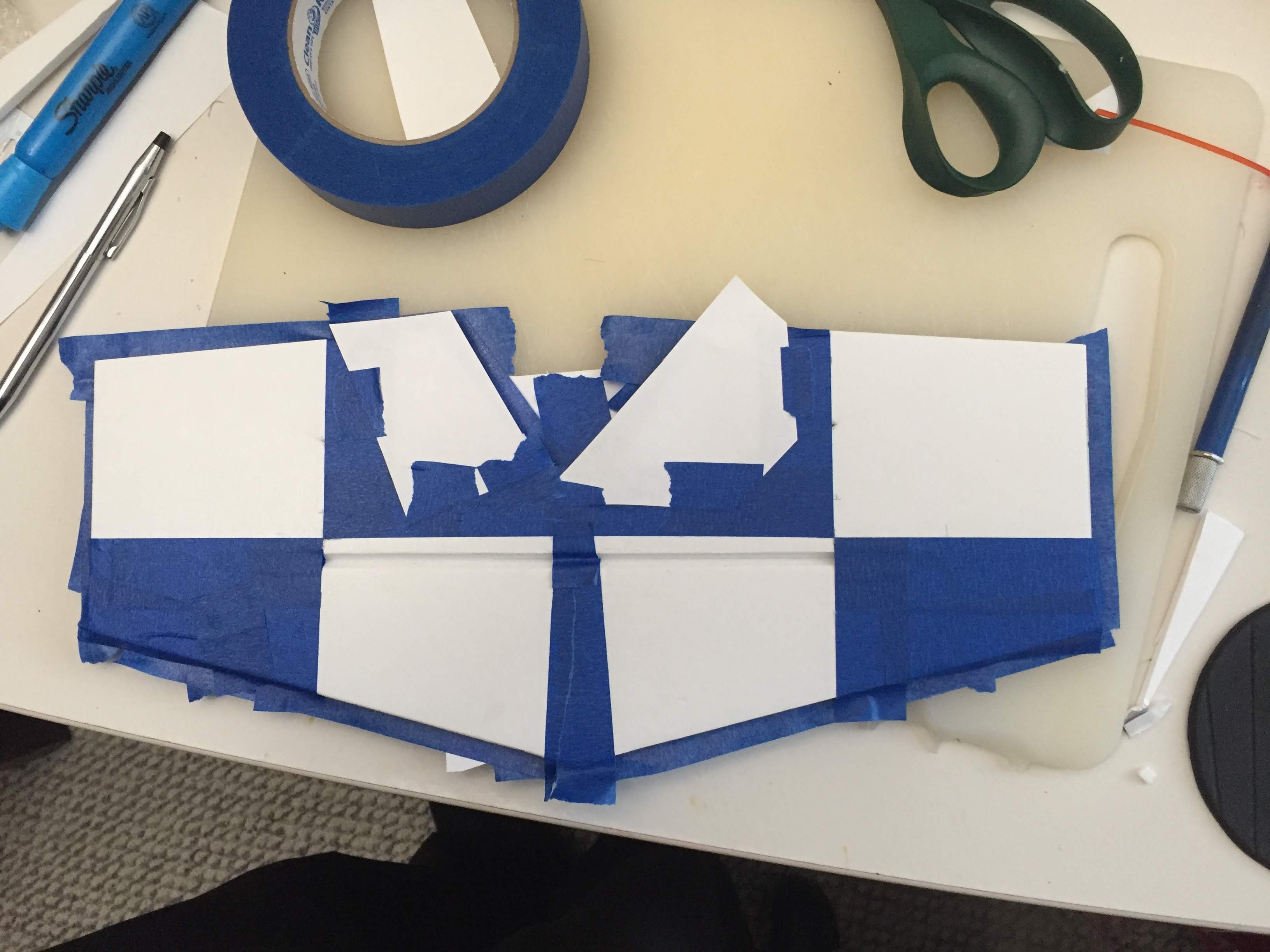
Then I painted a checker pattern on the bottom of the horizontal stabilizer:
IMG_6798.JPG

IMG_6800.JPG


IMG_6815.JPG
 

rcfred

Member
With the tail feathers done, it was time to close up the fuselage. I started by laying out the pieces on the building board:
IMG_6707.JPG

As you can see, there are 4 foam pieces across the top of the box: A reinforcement piece at the nose, a former at the front of the rear turtledeck, a little rectangle at the middle of the turtledeck to keep things aligned while gluing the turtledeck, and a triangular piece at the back to ensure that the rudder goes on straight. I started out by gluing all the joints on the bottom. I used paper surgical tape on the corners of the tapered section, both to reinforce them for belly landings and to keep the Gorilla Glue from oozing out:
IMG_6710.JPG

The curved bit at the front got the same treatment, albeit with some relief cuts to allow the tape to fit the curve:
IMG_6712.JPG

Once all the bottom joints were taped up, I turned the fuselage back over, glued in the formers/reinforcements, and made sure everything was square:
IMG_6714.JPG

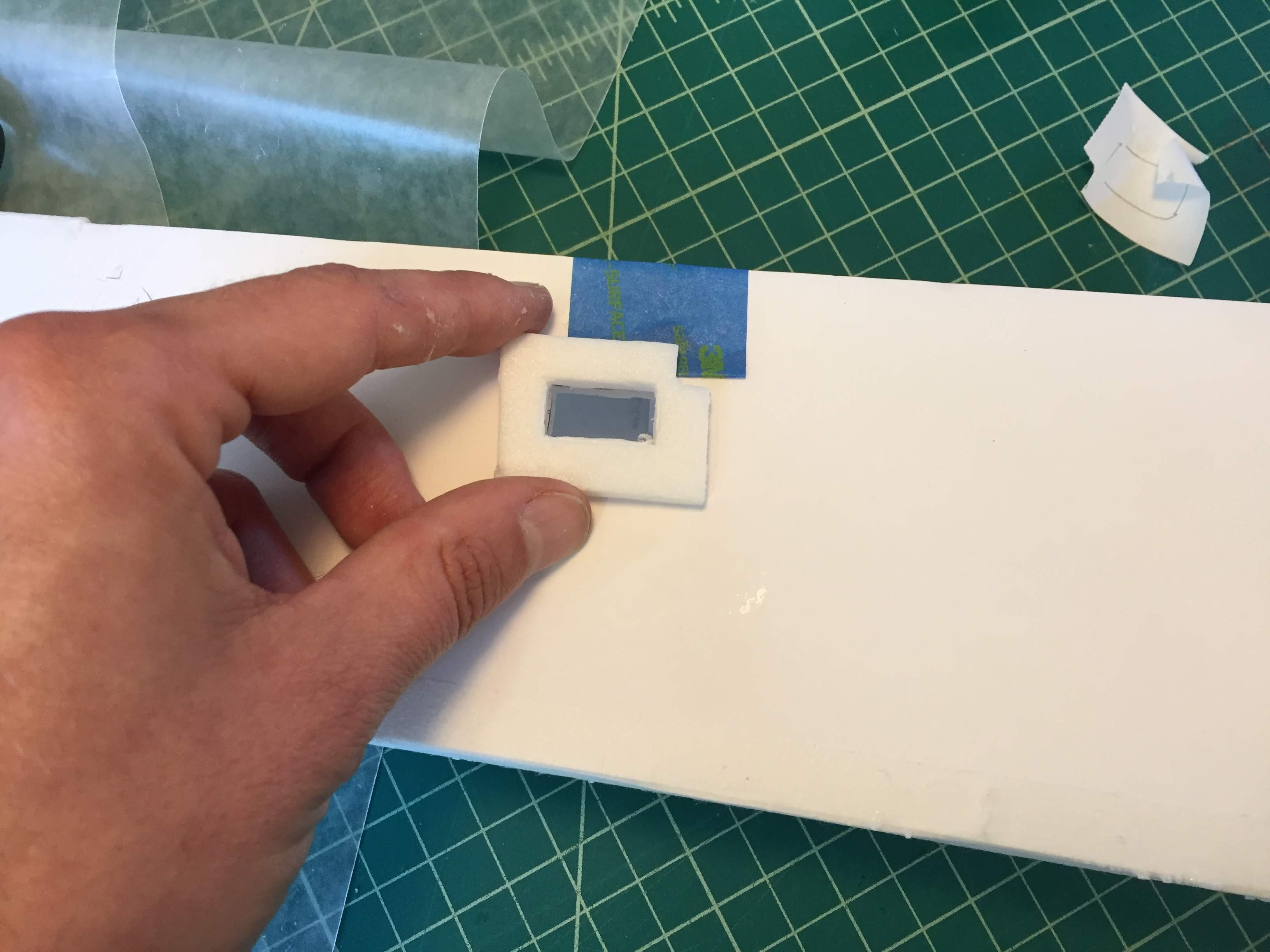
Once the glue had set, I cut holes for the servos and added some foam doublers. The doubler for the elevator servo needed a notch to accommodate the former:
IMG_6716.JPG

With the turtledeck still not attached, there was plenty of room to work inside the fuselage:
IMG_6718.JPG


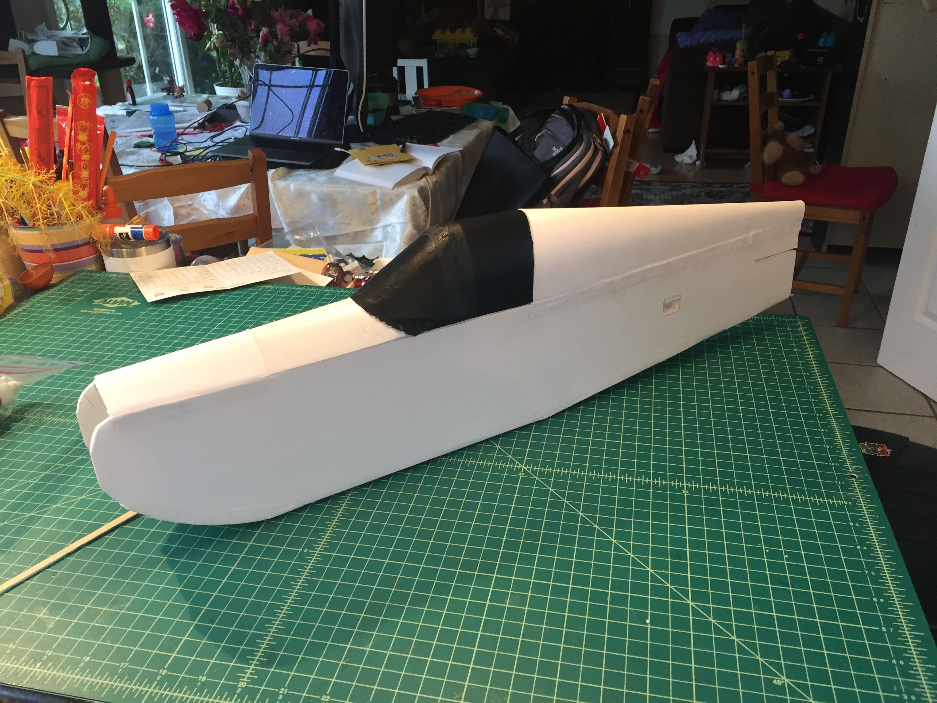
Next I glued on the turtledeck. I decided to try white craft glue for this joint, due to the paper-on-paper bond. Results were so-so. The water-based glue made the paper expand and wrinkle a bit. The wrinkles mostly went away over the next 24 hours as the remaining water evaporated, but still I think I'll use Foam-Tac next time. I kept the hatch in place while the glue set to ensure that the former was at exactly the right angle.
IMG_6814.JPG
 

rcfred

Member
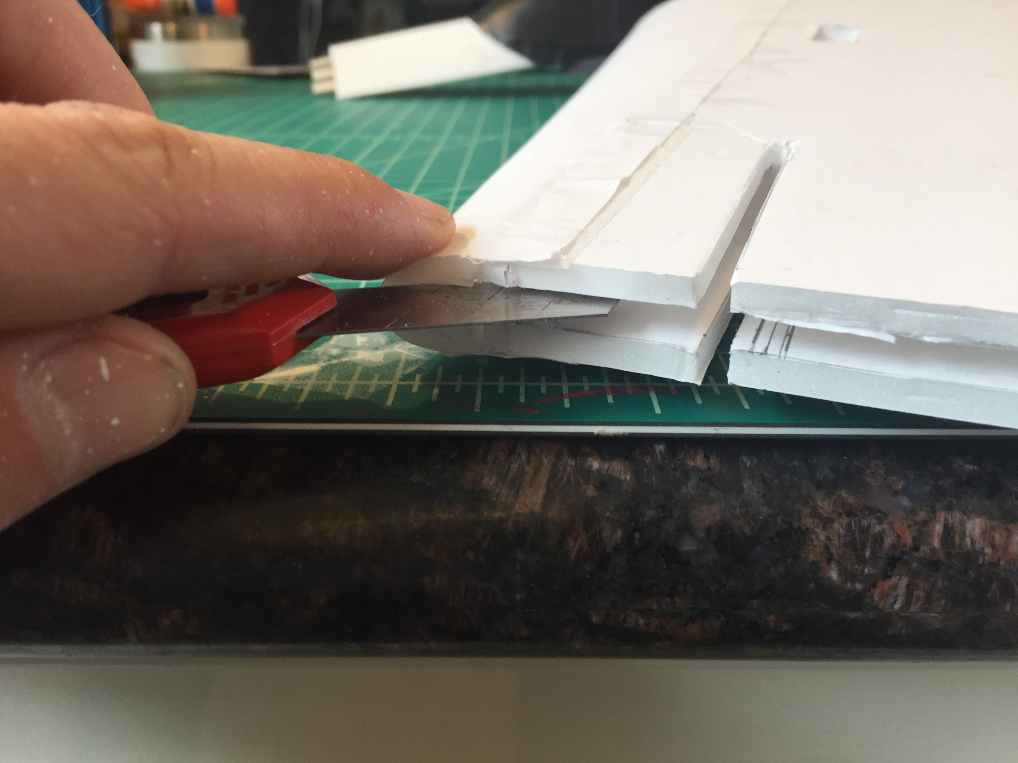
Next it was time to fit the tail feathers. The triangular reinforcement piece at the rear of the fuselage has a pre-cut slot for the rudder. I used that slot as a guide to cut a corresponding slot into the turtledeck:
IMG_6820.JPG

IMG_6821.JPG


The rudder itself had a bit of extra foam to trim away where it meets the turtledeck. I laid the fuselage on top of the rudder, traced the outline of the top of the turtledeck onto the rudder, and cut out that part of the foam:

IMG_6824.JPG

IMG_6823.JPG


Then I glued the horizontal and vertical stabilizers in place. It's starting to look like an airplane!
IMG_6828.JPG


Next I painted a checkerboard pattern onto the underside of the wings for visibility. It took a few steps: First apply a light base coat of white spray paint, then mask, then spray some more white at the tape edges, then red. I used cheap, nasty red Walmart spray paint, so I had to lay down multiple coats to get decent coverage.
IMG_6717.JPG

IMG_6801.JPG

IMG_6802.JPG

IMG_6803.JPG

IMG_6830.JPG

IMG_6831.JPG


Next I needed to figure out where to mount the wings. The FT3D design gives you some flexibility to move the wings forward or back for better CG. To figure out where the wing spar should pierce the fuselage, I stuck some servos into the servo slots at the back, laid an appropriate amount of pushrod wire on top of the elevator, stuck the power pod from Version 1 into the front of the fuselage, and put my smallest flight battery all the way at the front of the power pod. Then I found the center of gravity of the fuselage:
IMG_6838.JPG


By the way, that power pod is currently stuck halfway up a 100-foot eucalyptus tree, along with the rest of Version 1. So I might have to order a new motor for this build.
IMG_6875.JPG

Oops.

To get some servos for the new build, I turned to my original FT3D:
IMG_6819.JPG

Unfortunately, one of those metal-gear servos didn't survive removal. Or perhaps it just died while the airframe was in storage. Either way, I'll be using some 9-gram plastic-geared servos from another crashed airframe on the ailerons of this build. One of those servos turned out to have partially-stripped gear, but I was able to cobble together a working servo using parts from some other broken servos.
IMG_6903.JPG

I think I might need to order some more servos.
 

rcfred

Member
After some digging through my scrap bin, I found a motor. It's an NTM PropDrive 2826 1200kv. And it was in the scrap bin because one of the wires broke off inside the case. The other two wires weren't looking terribly healthy either.
IMG_7474.JPG

I opened it up and found there was still enough wire left to solder onto:
IMG_7477.JPG

So I fired up the ohmmeter and tested for continuity. It showed 0.2 ohms between all pairs of wires, and zero continuity between any of the wires and the stator. So the windings are still good!
IMG_7480.JPG
IMG_7481.JPG


The shortest wire had broken off upstream of the tinned section. I turned my soldering iron up to 800 degrees and melted the enamel off the end, then added some flux and tinned the wires underneath.
IMG_7489.JPG


Then I spliced on a length of silicone wire.
IMG_7491.JPG


I spliced some silicone wire onto the remaining motor leads, covered all the exposed bits with some fresh heat shrink, and routed the silicone wires out of the case:
IMG_7492.JPG


I soldered the other ends of the wires to an old 20A ESC. This is a Turnigy DLux ESC. It's lightweight for its time and has current sensing, but (and this is a pretty big "but") soft start is permanently enabled. The program box has a "soft start" flag (Remember when ESCs has program boxes?), but it just toggles between soft and softer... I'll just make sure not to let the throttle drop to zero while the plane is in the air. Else I'll have a bit of a surprise.
IMG_7517.JPG


Now it was time to see if those solder joints were actually sound. I put together a quick test stand from some scrap wood, overpropped the motor a bit with a 9x4.5E prop, and ran it up to full throttle for 10 seconds. Nothing exploded. The ESC measured 25A, which is about right. Then I put on an 8x4E prop, and the ESC showed 17A on a half-full 4S pack. So it should pull about 20A on a full pack, which is just right for this motor and ESC.
IMG_7509.JPG

Now it was time for a power pod. The spar channel on Version 2 is too tall for the power pod to go under or over it, so I need to use a cut-down power pod.
IMG_7522.JPG


I like to put a block of EPP foam at the front of my power pods to guard against prop strikes. I cut this one out of the packaging from a box of hard drives.
IMG_7523.JPG


Then I used craft glue to glue the EPP to the firewall and the body of the power pod:
IMG_7525.JPG

IMG_7530.JPG


Once the glue had set up, I used my needle files to open some holes in the EPP for the screws that hold on the motor:
IMG_7531.JPG

IMG_7532.JPG


The pod fits nicely into the fuselage with enough room for a 3S 2200mAh battery pack:
IMG_7533.JPG


The CG still looks ok in spite of the lighter motor. I haven't yet figured out where to put the BBQ skewers to lock the power pack in place. The wings will cover the most obvious spot. I may end up attaching the power pod directly to the spar channel with a velcro strap.

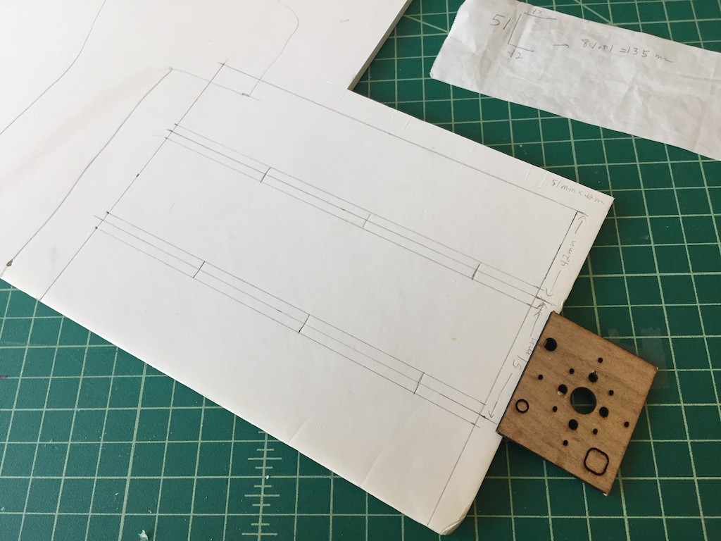
I've also fabricated my control horns out of the usual hotel keycards.
IMG_6899.JPG

IMG_7521.JPG


I copied the idea of the circular holes from a Twisted Hobbys control horn. The holes really help the control horns to grip the foam.
 

Attachments

  • IMG_7474.JPG
    IMG_7474.JPG
    625.8 KB · Views: 0
  • IMG_7477.JPG
    IMG_7477.JPG
    423.2 KB · Views: 0
  • IMG_7480.JPG
    IMG_7480.JPG
    362.6 KB · Views: 0
  • IMG_7480.JPG
    IMG_7480.JPG
    29.5 KB · Views: 0

rcfred

Member
I managed to squeeze in the remaining finishing steps for Version 2 in between the rest of this week.

I used a scrap of curved carbon from my first attempt at the elevator bracing to reinforce the tail skid.
IMG_7535.JPG


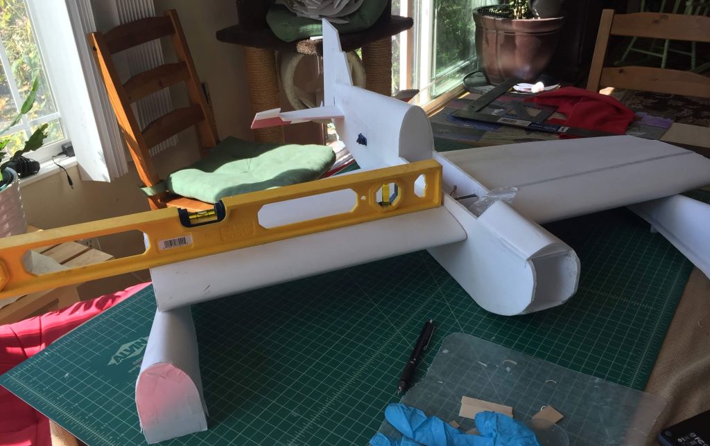
Then I glued on the wings. I used epoxy to bond the spar caps to the joiner and white Gorilla Glue for the remainder. Because the spar is the same thickness from root to tip, I was able to use a level to ensure the wings were straight. Much more convenient that way.
IMG_7538.JPG


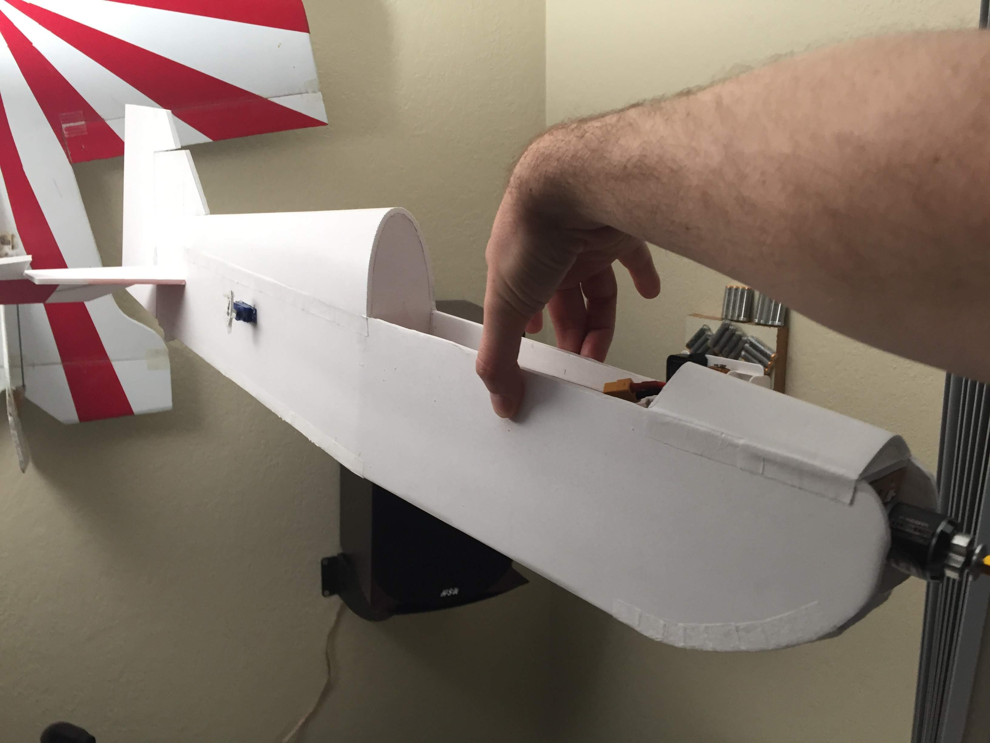
Next I had to figure out how to attach the power pod to the fuselage. I added some foam rails to the inside of the fuse to align the power pod vertically.
IMG_7539.JPG


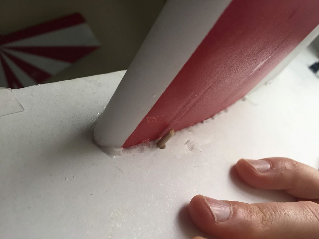
At the rear of the power pod, I ran a BBQ skewer underneath the bottom edge of the wing root.
IMG_7540.JPG


The skewer passed through the floor of the power pod. There wasn't really enough meat there to hold the skewer properly, so I made a bushing out of a plastic coffee stirrer.
IMG_7542.JPG

IMG_7544.JPG

IMG_7545.JPG


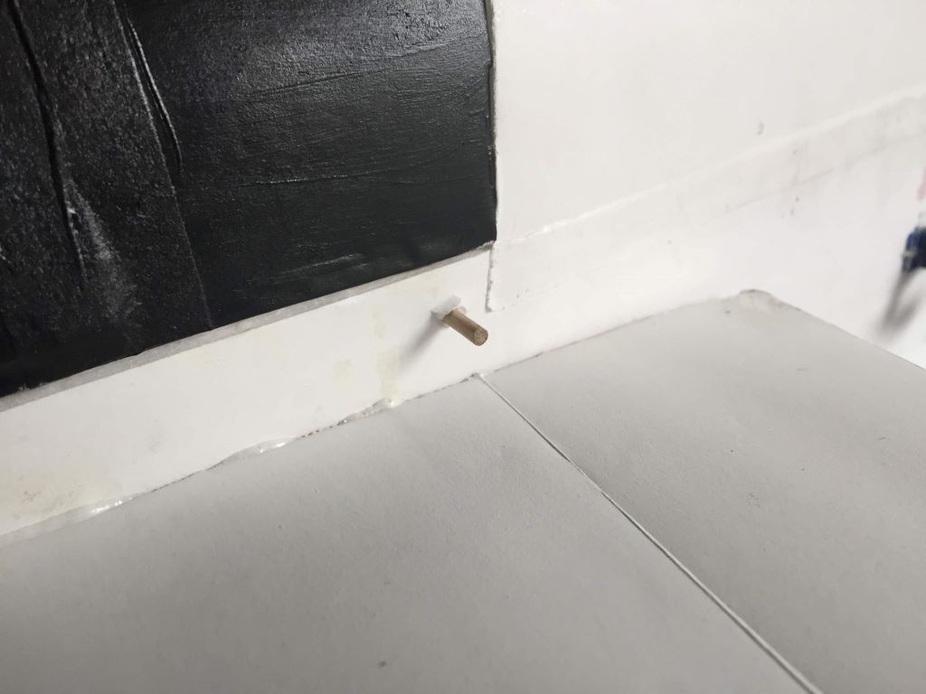
I used a second BBQ skewer to secure the hatch to the fuselage. It turns out there was enough room for the ailerons to move freely there.
IMG_7541.JPG


I ditched the idea of a radio tray because I couldn't get all the wires to reach properly. Instead I just velcro'd the receiver to the side of the fuselage.
IMG_7546.JPG


Finally I added some wingtip devices. The style that I used on the previous prototype would have been weird on a wing with such a long tip chord, so I mounted the fins at the wingtips and adjusted the shape a bit. I started with some rectangles of EPP foam sheet and cut some reliefs at the back to avoid binding up the ailerons. Then I made a template in the shape of the front of the wing and cut around the template.
IMG_7547.JPG

IMG_7549.JPG


I glued the side force generators onto the wingtips with some Foam-Tac. Here's the completed V2 plane with my original FT3D for scale:
IMG_7555.JPG

IMG_7560.JPG
 

rcfred

Member
I took the V2 prototype out to the flying field yesterday morning. The maiden flight was... short. The first thing I noticed after getting the plane in the air was that the ailerons were reversed. The second thing I noticed was that the rudder was also reversed.
Oops. That was the first time I've made that mistake -- and definitely the last! I managed to get the plane onto the ground without any major damage though.

After correcting the directions of the servos, I took off again and quickly found that the plane was tail-heavy. My estimate of the CG was off by almost half an inch. The control throws were also off. The elevator had too much throw and the ailerons too little. The twitchy elevator was a bit of a surprise. I had thought that increasing the wing chord would make the elevator less effective, but instead it's quite a bit more effective. I cut the elevator throw down by about a third with my radio and added a bunch more expo, which settled that down. After turning up the travel on the aileron servos to +/- 150% I had enough travel for most maneuvers, but not quite enough to hold a decent hover without torque rolling. I corrected the center of gravity for the time being by using a much larger battery than I had planned.

I was pleasantly surprised by the amount of thrust the old motor from my parts bin produced. I had grown accustomed to its performance with the wires mostly broken. Soldering on fresh leads made a big difference. On 4S with am 8x4E propeller there was enough thrust for just about any maneuver. I was even able to drop down to a 3S pack and 9x4.5E prop and have enough power to hold a knife edge.

I tried to get some video once the airframe was roughly trimmed out. By that point in the day, the only charged battery I had was a big 3S 2200mAh pack, the wind had picked up enough that I could almost fly backwards, and the guy holding my phone wasn't able to see the screen in the bright sun. But I was able to piece together 2 minutes of ok video afterwards:

I'll make some adjustments during the week and hopefully will be able to get some better flights in next weekend. In the meantime, here are some outdoors photos of the plane:
IMG_7562.jpg
IMG_7563.jpg

IMG_7564.jpg

IMG_7567.jpg
 

rcfred

Member
During the week, I moved the power pod forward about 1/4 inch -- about as far is I could go. Now the CG is pretty good with a 4S 1300mAh pack, though it's still tail-heavy if I put the 4S 1050mAh pack in. I also dialed up the ailerons as far as they would go using the controls on my radio. The plane is flying considerably better now. Here's a clip of it flying on 4S this morning:
 

rcfred

Member
I finally had some time to draw the plans for Version 2. Here they are. I'm calling this Version 2.1 because I've made a few tweaks beyond the current prototype:
  • Added 1/2 inch to the fuselage to clear up CG issues
  • The canopy is now 3 pieces instead of 2 for a more bubble-like appearance
  • The tips of the rudder and elevator have some cosmetic improvements
  • Left some paper on the bottom rear of the fuselage to cover up the seam (instead of using paper tape)
 

Attachments

  • FR3D V2.1.dxf
    289.7 KB · Views: 0
  • FR3D V2.1.pdf
    291.6 KB · Views: 0