Li'l Phil

Tench745

Master member
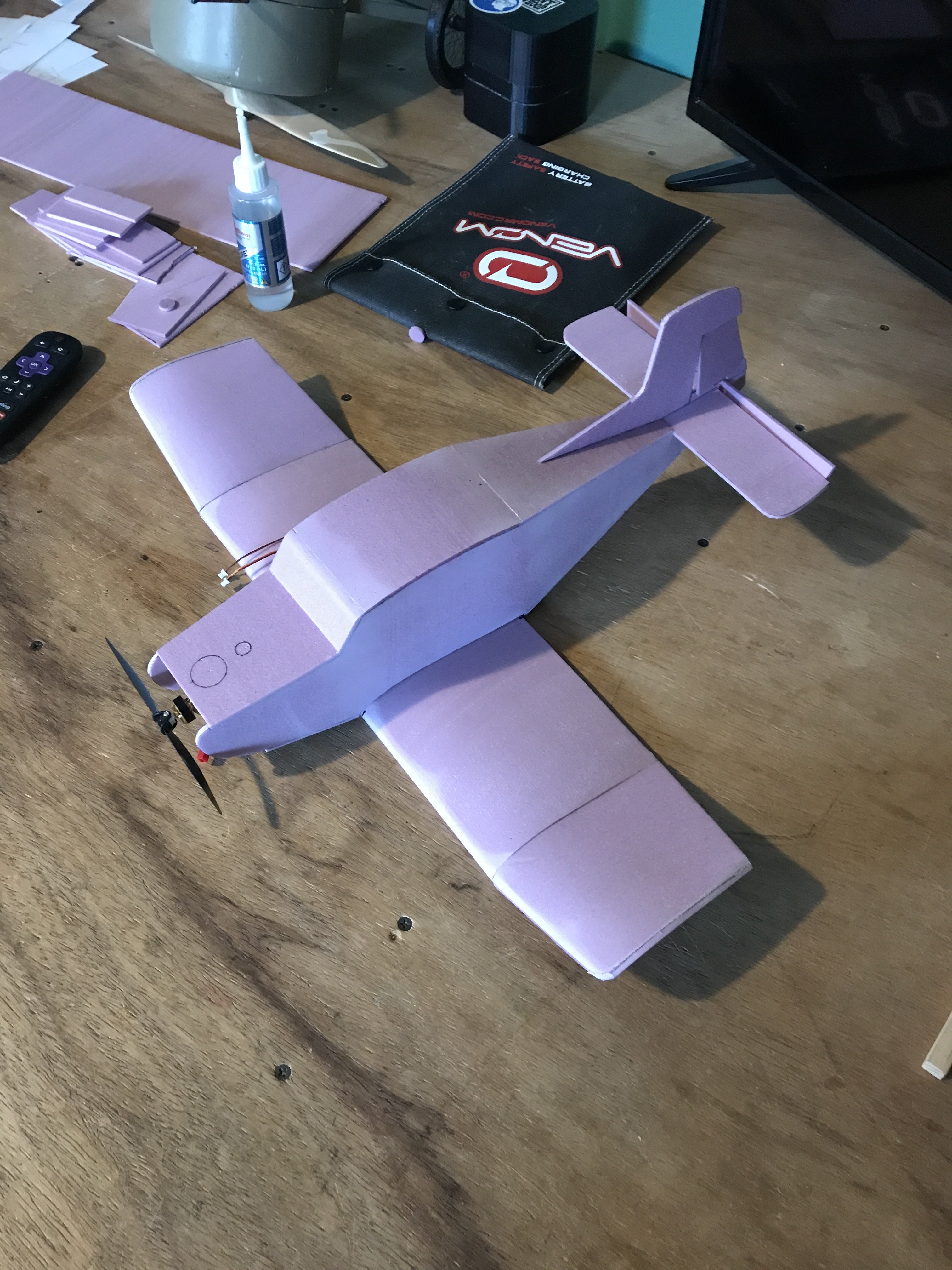
I've posted some pictures on the Flite Test Fans Facebook page of this little plane and the amount of interest shown has been startling. With over 100 "likes" and multiple requests for plans I figured I should post a build thread and plans for the little guy.
(Plans here: https://forum.flitetest.com/index.php?resources/lil-phil.377/)
IMG_2584.JPG IMG_2598.JPG
I should start all of this by giving credit where it is due. This design is based on a balsa plane designed by Hilmar Lange called the Phat Phil. I took his plans, printed them out at 80% size and modified them as necessary while I was building. I've decided to call this version the "Li'l Phil" in honor of the original. Aside from the reduced size, the largest changes were eliminating the landing gear and modifying the size of parts to support 1/8" XPS foam sheet construction.

The construction of this model isn't particularly difficult, but cutting the foam sheets requires more tooling than a beginner modeler might have.
I have a jig I made for cutting foam planks. It's relatively simple, just a pair of stops to hold the wire and a pair of shims to hold the wire at the right height. For this project I shaved down a piece of 1" XPS foam into 1/8" planks.
That's it for tonight. I have some work to do to finish up the plans so I'll be posting those with some more construction details as I go.
 

Attachments

  • IMG_2576.JPG
    IMG_2576.JPG
    1.6 MB · Views: 0
  • IMG_2577.JPG
    IMG_2577.JPG
    1.4 MB · Views: 0
Last edited:

Tench745

Master member
The build process for this is relatively straightforward and similar to that of the Phat Phil. If you download those plans there is a comprehensive build guide included, much of which is applicable to this version.
I used BSI Foam Cure glue exclusively in the construction of this model and I recommend it or a similar glue (Foam Tac, FloraCraft Clearstik, etc). I apologize for a lack of in-process pictures, I did not intend to do a build thread or release plans for this when I was building it. Hopefully the descriptions and accompanying pictures give enough information. Inevitably I will have missed something, so please point out any errors and ask questions so I can correct and clarify. I've already identified a couple errors in writing up this build guide and am uploading V1.1 of the plans.

The first step is building the central skeleton of the fuselage. Take both "Wing Saddle" pieces and glue them into the notches on the "Fwd. Bulkhead" and "Rear Bulkhead"

When this is dry, glue one side onto the corresponding fuselage side, lining up the bulkheads with the respective marks on the fuselage skin and the curve of the wing saddle with the curve of the fuselage skin. Repeat for the other side.
The plans are drawn with reference lines marked on the INSIDE of the skin, so be sure you are putting the skin with the pushrod cutout on the right (starboard) side of the airplane.

When both sides are glued to the bulkheads, you can glue in the "RX Tray". I didn't really need this piece to hold any equipment, but it acts as a stiffener for the fuselage sides and holds them square to the forward bulkhead.
IMG_2611.JPG
(Ignore the cutout in the RX Tray, it's not necessary and not included in the plans)

Once this central structure is established, the tail can get pulled together and the aft edge glued. The "Upper Fuse Skin" can be glued on at this point. Make sure you glue it on right-side up, so the pushrod cutout is on the left (port) side of the fuselage.
The "Lower Tail Skin" can also be glued on with the leading edge flush to the front of the rear bulkhead.

Much like the tail skins, the "Cowl Top" can get glued on. The forward edge of this piece pushes up against the tabs in the fuselage sides. The "Windshield" then gets beveled to fit snugly against the Cowl Top and glued in place. The windshield is rectangular, so orientation is not important.

Now is a good time to glue the "Firewall" in place. There is some thrust angle designed in, and the firewall is shaped accordingly. The right side of the firewall is longer than the left,so be sure it's oriented correctly and align it to reference marks on the fuselage sides.

With the Firewall in place, now we turn to the "Batt Tray". Glue both "Battery Tray Rt. Side" and "Battery Tray Lft. Side" their corresponding marks on "Batt Tray", lining up the back edges with the back edge of Batt Tray.
Trim the Batt Tray and Battery Tray Sides to match the thrust angle of the firewall if necessary and then glue in place, matching reference lines on the fuselage sides.
With the battery tray assembly glued in place the "Cowl Bottom" can get glued on with the back edge lining up with the aft side of the Fwd. Bulkhead.

More to follow.
 

Tench745

Master member
The last post finished out the main fuselage structure. Next we need to form the wing.

There are two types of ribs for the wing; labeled "Rib" and "Wingtip Rib." Two pairs of Ribs get doubled up and then glued at either end of the "Lower Wing Skin" panel. The remaining four ribs are glued to the Lower Wing Skin at the marked positions. The Upper Wing Skin can be pre-curved by rolling over the edge of a table, and then glued onto the lower skin and ribs; aligning the leading edges of both panels. The doubled end ribs then get sanded until they form an angle 25° from vertical.

The wingtips assemble similarly, but are a little more intricate.
The lower skin gets a shim under the trailing edge, tapering from 4mm at the wingtip to nothing where it meets the main wing panel. You can tape or lightly glue this shim onto the underside of the "Wingtip Lower Skin." This will be removed later and helps us build in a little washout to prevent tip-stalls. (Sorry, I forgot to add it to the plans, you'll have to make your own.)

With the Wingtip Lower Skins appropriately shimmed the Wingtip Ribs can be glued onto the marked locations. The last two Ribs are glued onto the Wingtip Lower Skin at a 25° angle. The "Wingtip Upper Skin" can then get pre-curved and glued on, aligning the leading edges of both upper and lower panels. If everything went as planned, the curve on the inboard end of the Wingtip Upper Skin should match the top of the angled Rib. This can then get sanded lightly for a nice even mating surface. When the glue on these pieces is entirely dry you can remove the temporary shim.

Now we can mate the wingtips to the main wing. Included on the plans is the "Wingtip Dihedral Gauge". Slide this under the leading edge of the wingtip panel and butt it up to the doubled ribs of the main wing panel. In a perfect world you will have a nice, even seam here, but in the real world it will probably need some tweaking. Just sand as necessary until the panels fit together nicely when the Dihedral Gauge is under the wingtip panel. Then glue the wingtips onto the main wing.
IMG_2628.JPG
The last but not least of the foam work: lightly sand the outboard edges of the wingtip skins and glue on the "Wingtip Endcap" pieces.
IMG_2629.JPG
Test fit the wing to the fuselage and lightly sand the wing saddle until they fit nicely. The lower surface of the wing should make a straight line from the Cowl Bottom to the Lower Tail Skin.


Now we can start on the mounting system for the wing. There are two "Plywood Wing Dowel Tabs;" these slide into the two slots cut in the upper and lower wing skins and a 1 1/4" long piece of dowel (I used a bamboo skewer) glues into the holes. The pictures pretty much tell the story here. The flat end of the dowel tabs should be flush with the bottom of the wing which will make the dowel parallel to the lower surface of the wing.
IMG_2627.JPG IMG_2630.JPG
Now set the wing in place on the fuselage and press it forward until the dowel forms and indentation in the Fwd. Bulkhead. Cut a hole through the bulkhead to allow the dowel to pass through and test the fit again. Enlarge the hole as necessary until the wing fits right. Don't worry if the hole got a little large, we're about to fix that. Put some glue on one side of the "Plywood Wing Mount," slide it part-way onto the wing dowel, then put the wing in place, using the wing and dowel to hold it in the right place on the Fwd. Bulkhead while the glue dries. You can see the Plywood Wing Mount at the left side of the photo below.
IMG_2611.JPG
To hold the trailing edge of the wing in place on my model I embedded a pair of neodymium magnets into the upper wing skin and the wing saddle, but anything that can hold it in place will be fine. The dowel does most of the work holding things together here and this plane won't do inverted anyway, so we don't have to worry about negative Gs pulling the wing off.


That's it for now. Next time: electronics.