Hi all!
So I'm on the home stretch, and have a few questions maybe you could help me out with. I love input. I'll post a string of pictures in case you're like me and enjoy looking at what keeps people up late at night building stuff. It's fun. This is my first plane of my own design, and Josh was right, designing is awesome. And in this case, since I stuck with things I already knew from FT, not that difficult! So here goes-
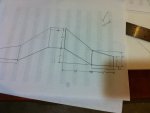
As you can see, the "plan" has been approved. No turning back now.

So I guess you just draw some lines on the foamboard? Yup, but you have to actually think about the shape of your plane vs the shape of the foam board and adjust accordingly, I had some unacceptable seams at first. I really wanted to build the semi symmetrical airfoil you see mocked up there but I wasn't there yet, and figured I needed to do what I knew first, and do it next time. Just build something!

More lines. Gotta get a square so I can draw lines more... squarely.

And the craft has a bottom. I just taped the seams, folded back, filled with glue and taped over, like in the versa. Next time I build this I will have thought ahead and cut out more widgets, notches, holes and what not. If I do this a bunch, I may be able to think ahead and not have to cut holes while the plane is inconveniently glued together!

The spars, three layer for the big section, two layer on the outside. Error here was not making them contiguous. I left a space for the vertical stab, between the bigger inner section and the outer smaller bit, which fits nicely but does nothing for strength. Need ideas for engineering that particular joint! Any one? Help?

It's oh so versa. Ok. That's... tall. Hope that works. I did the exp. airlines thing with the peeling back of the paper inside. Works nice, not as strong as the FT method. Would work awesome with ribs. I might do ribs for the semi symmetrical shindig.

Quick! Tape it together haphazardly! I want to see what it looks like. Oh kind of weird, hope she'll fly. Baby blender, et al for scale comparison. It's pretty big. For the plans, I used the scale 1mm =1cm, so it didn't look big on paper, but it's over two meters! This thing will look awesome if it flies.

Ok. What? Well, David said to go big on the stabilizers and trim if needed. That's what David said, so I certainly listened. Not sure if that is a good place for it. I'm putting the elevons on the outer wings past the stab. They will be 6cm long and 45cm wide. Think that's good enough?
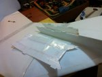
I was going to go for a pusher config, but truly, I have had headaches with that concerning cg on the versa. That's because my motor is way way heavy but still, I wasn't trying to chuck this thing in the air from the poorly designed outer wing! So, ala the mighty Kraken, I have joyously decided to go with two DT 750's! How to mount them... You guys ever hear of a "power pod?" I think I'll just use this plan I have here and make it longer and add a diagonally cut top thingy. I measured angles and everything, and guess what? It fits!
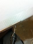
Popsicle sticks are comforting. Familiar. Drilled it on the bias as they say. I actually thought about how to do this for a few minutes. Then I remembered, maybe use skewers in the foam and through some wood like every swappable you've ever built! Works.
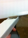
Better than I expected. This measuring thing sure is handy. I used the metric system and boy is it a lot easier for me. Well for that angle I used a protractor so that's pretty much the one system I guess. But I measured that angle on a line that I drew in a metric way! And I looooved it! I mean. A lot. Why don't we all use that again? Why inches? Is it really worth holding onto, America? I'm for metric, sign me up. Anyway, I'm so very pleased with how happily solid, yet removable this thing is.

This is a weird picture and I don't know why it's here. You can see the silly Popsicle stick I had glued on the top of the wing to hold on the pod, which I did away with as you'll see in the next picture.

I mean, that's your idea? That's how you are going to hold the nacelle in place? Have you any other ideas?

Ah yes, I like that much bettah! Popsicle stick inside the wing, could even be put in the plans, so you could do it from the inside without shenanigans and big holes!
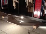
And these are upside down I guess. Idk why, but I'm going post this thing before I lose the attachments! Again. They only hang out for an hour? I'd even go so far as to say I was... dissatisfied.

I ended up putting a big long piece of angled aluminum stock to brace the whole wing on the bottom, got tired of trying to find carbon fiber. Not too heavy, but not too light. Might do the job though. But hey, Anyone know a good way to attach a wheel to the pod? I think maybe a will do two in the back and one up front in the middle maybe? Was it the fowl flyer that had a really cool gear that would work here? What does josh use on the Kraken? I think he may have had something like that on the big cruzer, I'll have to look at that episode.
So in review my questions are:
Ideas on that spar joint on the outside? And all joints for that matter?
Two meter wingspan, 6cmx45cm elevons on the outside section, any thoughts on the appropriateness of that?
Landing gear? Help? Episode referral?
Thoughts on spar or construction methods to make stiffer?
Two DT 750's enough? With 11x4.7? Probably won't be too fast, but I don't think these flat bottom airfoils do well at speed, I think I just want to maybe drop bombs and such.
I thank you for taking a look at my creation, I would appreciate any input wholeheartedly!
Thanks again.
Patrick
So I'm on the home stretch, and have a few questions maybe you could help me out with. I love input. I'll post a string of pictures in case you're like me and enjoy looking at what keeps people up late at night building stuff. It's fun. This is my first plane of my own design, and Josh was right, designing is awesome. And in this case, since I stuck with things I already knew from FT, not that difficult! So here goes-

As you can see, the "plan" has been approved. No turning back now.

So I guess you just draw some lines on the foamboard? Yup, but you have to actually think about the shape of your plane vs the shape of the foam board and adjust accordingly, I had some unacceptable seams at first. I really wanted to build the semi symmetrical airfoil you see mocked up there but I wasn't there yet, and figured I needed to do what I knew first, and do it next time. Just build something!

More lines. Gotta get a square so I can draw lines more... squarely.

And the craft has a bottom. I just taped the seams, folded back, filled with glue and taped over, like in the versa. Next time I build this I will have thought ahead and cut out more widgets, notches, holes and what not. If I do this a bunch, I may be able to think ahead and not have to cut holes while the plane is inconveniently glued together!

The spars, three layer for the big section, two layer on the outside. Error here was not making them contiguous. I left a space for the vertical stab, between the bigger inner section and the outer smaller bit, which fits nicely but does nothing for strength. Need ideas for engineering that particular joint! Any one? Help?

It's oh so versa. Ok. That's... tall. Hope that works. I did the exp. airlines thing with the peeling back of the paper inside. Works nice, not as strong as the FT method. Would work awesome with ribs. I might do ribs for the semi symmetrical shindig.

Quick! Tape it together haphazardly! I want to see what it looks like. Oh kind of weird, hope she'll fly. Baby blender, et al for scale comparison. It's pretty big. For the plans, I used the scale 1mm =1cm, so it didn't look big on paper, but it's over two meters! This thing will look awesome if it flies.

Ok. What? Well, David said to go big on the stabilizers and trim if needed. That's what David said, so I certainly listened. Not sure if that is a good place for it. I'm putting the elevons on the outer wings past the stab. They will be 6cm long and 45cm wide. Think that's good enough?

I was going to go for a pusher config, but truly, I have had headaches with that concerning cg on the versa. That's because my motor is way way heavy but still, I wasn't trying to chuck this thing in the air from the poorly designed outer wing! So, ala the mighty Kraken, I have joyously decided to go with two DT 750's! How to mount them... You guys ever hear of a "power pod?" I think I'll just use this plan I have here and make it longer and add a diagonally cut top thingy. I measured angles and everything, and guess what? It fits!

Popsicle sticks are comforting. Familiar. Drilled it on the bias as they say. I actually thought about how to do this for a few minutes. Then I remembered, maybe use skewers in the foam and through some wood like every swappable you've ever built! Works.

Better than I expected. This measuring thing sure is handy. I used the metric system and boy is it a lot easier for me. Well for that angle I used a protractor so that's pretty much the one system I guess. But I measured that angle on a line that I drew in a metric way! And I looooved it! I mean. A lot. Why don't we all use that again? Why inches? Is it really worth holding onto, America? I'm for metric, sign me up. Anyway, I'm so very pleased with how happily solid, yet removable this thing is.

This is a weird picture and I don't know why it's here. You can see the silly Popsicle stick I had glued on the top of the wing to hold on the pod, which I did away with as you'll see in the next picture.

I mean, that's your idea? That's how you are going to hold the nacelle in place? Have you any other ideas?

Ah yes, I like that much bettah! Popsicle stick inside the wing, could even be put in the plans, so you could do it from the inside without shenanigans and big holes!

And these are upside down I guess. Idk why, but I'm going post this thing before I lose the attachments! Again. They only hang out for an hour? I'd even go so far as to say I was... dissatisfied.

I ended up putting a big long piece of angled aluminum stock to brace the whole wing on the bottom, got tired of trying to find carbon fiber. Not too heavy, but not too light. Might do the job though. But hey, Anyone know a good way to attach a wheel to the pod? I think maybe a will do two in the back and one up front in the middle maybe? Was it the fowl flyer that had a really cool gear that would work here? What does josh use on the Kraken? I think he may have had something like that on the big cruzer, I'll have to look at that episode.
So in review my questions are:
Ideas on that spar joint on the outside? And all joints for that matter?
Two meter wingspan, 6cmx45cm elevons on the outside section, any thoughts on the appropriateness of that?
Landing gear? Help? Episode referral?
Thoughts on spar or construction methods to make stiffer?
Two DT 750's enough? With 11x4.7? Probably won't be too fast, but I don't think these flat bottom airfoils do well at speed, I think I just want to maybe drop bombs and such.
I thank you for taking a look at my creation, I would appreciate any input wholeheartedly!
Thanks again.
Patrick
Last edited:
