Help! Need help with my first two designs.

Turbojoe

Elite member
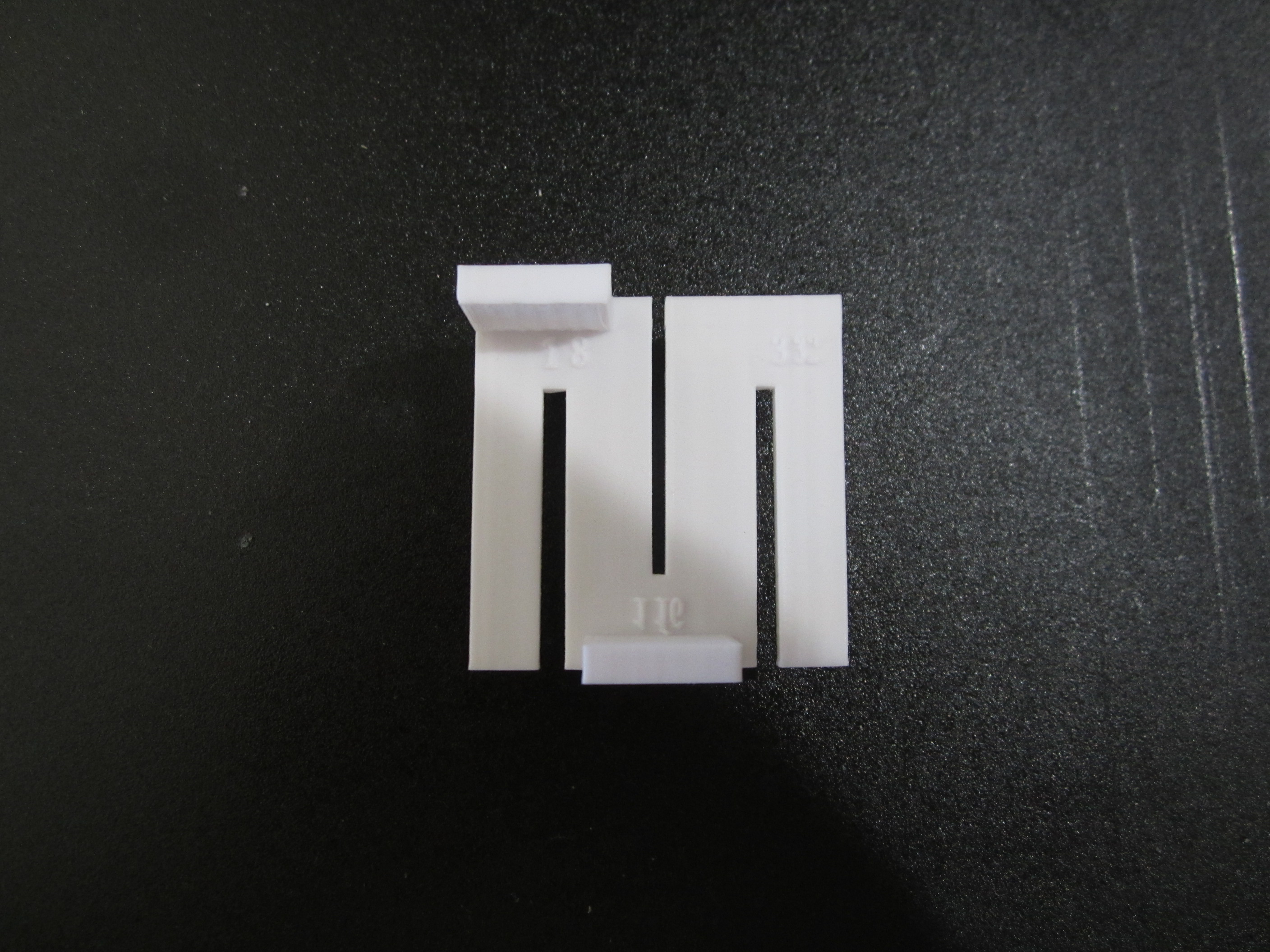
So I've been playing around with Tinkercad for a few minutes at a time for a while now. Things are "clicking" to the point that I designed and printed two items. The first is a replacement for the flimsy and loose fitting House of Balsa upright for setting ribs at 90 degrees. For the most part my tool came out right except for skewing of the holes for the neodymium magnets. I set the magnet hole diameter to .236 and the finished product came out at .217-.230 as measured at loose and tight areas of the hole. Text for slot sizes came out just OK but the slashes didn't print. No big deal on that but the magnet holes baffle me as to what I did wrong. Surprising is that the rib slots came out perfect! Any suggestions?

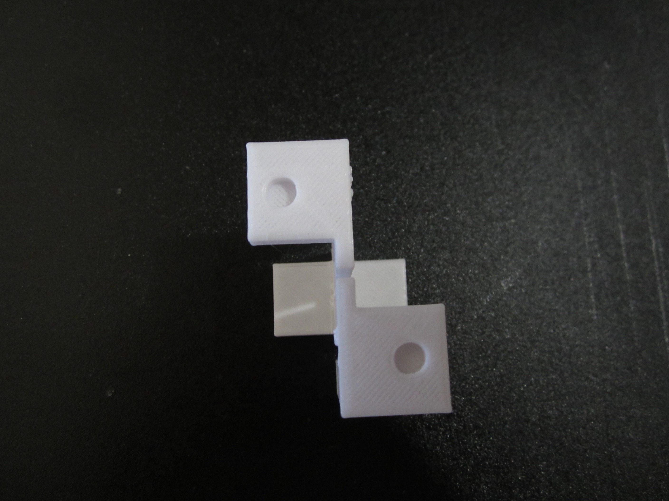
I also had the same magnet hole problem on the fixture adapter I made to use with my Eldon J. Lind magnet building system. Everything about the part is fine except the magnet hole. Skewed just like on the upright. Again, I'm lost as to what I did wrong.

I've got a ton of other things I want to design and print but not until I get this hole skewing problem whipped.

Thanks for ANY help guys.

Joe
 

Attachments

  • Upright 1.JPG
    Upright 1.JPG
    1.3 MB · Views: 0
  • Upright 2.JPG
    Upright 2.JPG
    1.1 MB · Views: 0
  • Upright 3.JPG
    Upright 3.JPG
    841.4 KB · Views: 0
  • Upright 4.JPG
    Upright 4.JPG
    963.5 KB · Views: 0
  • Adapter 1.JPG
    Adapter 1.JPG
    374.6 KB · Views: 0
  • Adapter 2.JPG
    Adapter 2.JPG
    320.5 KB · Views: 0
  • Adapter 3.JPG
    Adapter 3.JPG
    409 KB · Views: 0
  • Adapter 4.JPG
    Adapter 4.JPG
    387.2 KB · Views: 0

Turbojoe

Elite member
Just for grins I created a test piece 1" square by .180 thick. Added a hole to the center with a .117 depth diameter .236. The hole was skewed in this test as well. Hole was from .209 - .223. Even the largest area was still smaller than the .236 that I wanted. Depth was only .112. I'm screwing up somewhere. I just don't know where.....

Again, I'm using TinkerCad and latest version Cura for slicer.

Joe
 

kdobson83

Well-known member
Most PLA, and I assume ur using PLA, will expand when it cools. I think other plastics will too, but I know PLA does. You have to calibrate your slicer and printer to accommodate for the expansion. There are tutorials on YouTube explaining on how to calibrate them. It's a long process of printing test prints, measuring, and adjusting settings. My slicer/ender 3 printer arn't calibrated at all and I don't have the time to figure out how... Life in the form of two kids, a needy wife, my Xbox, and FT are in the way lol.
If all your doing is making magnet holes to glue in magnets, I make the hole a little bigger to accommodate the expansion. Say I have a round magnet with a radious of 3mm, I would CAD the hole at 3.2mm. the magnet slides into place. With a little super glue it won't go anywhere.
That's my advice. You'll either have to calibrate your slicer settings with your plastic and printer, or run a few trial and error prints. Maybe even design something small with a hole at say 5mm, print it, and measure the hole after printed. Figure out the difference as a percentage, and add that percentage to your future holes. Quicker and easier than calibrating but maybe not as accurate.
 

Turbojoe

Elite member
The problem is not so much the hole diameter (I can easily compensate) but that the hole is skewed or oblong. I just printed out another test plate with the same 1" square .180 thick. This time I set the hole for .500 diameter. The print came out with the tight side of the hole at .474 and the long side at .495. I could adjust the hole size to maybe get it close but it's just a round hole. That shouldn't be hard for the machine to reproduce it round.

Joe
 

kdobson83

Well-known member
The problem is not so much the hole diameter (I can easily compensate) but that the hole is skewed or oblong. I just printed out another test plate with the same 1" square .180 thick. This time I set the hole for .500 diameter. The print came out with the tight side of the hole at .474 and the long side at .495. I could adjust the hole size to maybe get it close but it's just a round hole. That shouldn't be hard for the machine to reproduce it round.

Joe
Hmm, could be an issue with how your using cad. When making a hole, your picking the cylinder shape and selecting hole correct? Then set both the measurements on that cylinder to 5mm. If your not doing that or don't recognize what I'm talking about I can screen shot an example for you.
I have noticed when moving objects around in cad that sometimes it'll change the size of the object, especially when flipping it. Try locking the object before rotating or flipping. Always double check it's diameter to make sure it didn't change on you. I had this exact same issue when designing my son a cup holder for his bed rail. It was changing the shape of the octogon hole I put in it to hold a nut when I rotated it to put it in place. It was oblong instead of symmetrical...
 

jhitesma

Some guy in the desert
Mentor
If the holes are printed vertically then it could be your Z steps are slightly off. You could try printing something like a 20cm cube and making sure that it's vertical measurement is actually 20mm. If not then you'll want to adjust the z steps in your printers firmware which you might be able to do with manual gcode commands but is usually best done by reflashing after reconfiguring the firmware (assuming you're running Marlin.)

If the holes are printed parallel to the print bed and they're not perfectly round then something is probably physically skewed on your printer - or the X or Y steps are slightly off. Again a 20cm cube is a good simple way to test. Print it with 2-3 perimeters and 15-20% infill to try and get the best results. Then you can measure it to see how accurate your printer is in each dimension and if there's any skew.

If you can't adjust the steps you could always fudge in the slicer by figuring out how far off your printer is and then resizing the part a small % in just one axis to compensate.
 

Turbojoe

Elite member
I was Googling this morning looking for calibration adjustments for my printer. ( Ender 3) I started seeing a lot of posts about wheel problems so I checked mine closely. When moving the X and Y axis by hand there was "notchiness" at several spots especially bad close to center of the build area. I started feeling the wheels and there was one on each axis with nicks in the wheel running down into the contact area. Using a scalpel I sliced off the protrusions and reinstalled. Massive improvement but I'm still going to order some replacement wheels. I did two more test prints and the magnet holes are now only .005 out of round rather than the .020+ that it was before. The 20mm test cube prints out at X= 20.17mm Y= 20.13mm Z= 19.91mm. If it can get any closer to exact measurements I'm hoping new wheels will get it there.

Joe
 

FlyVirginia

Member
on tinkercad when you select a cylinder the options allow you to choose how many sides. Set it to max and it should be OK
 

tanyoon

New member
A little late to the game here but it definitely sounds to me like a belt tensioning issue especially with how the holes are oriented for printing. I ran into this at first when I built my Prusa kit.

Unfortunately without a belt tensioning screw (which I don't think the Ender 3 has, nor the Prusa in my case) it's quite a bit of trial and error. The belts have wires running their length so you can't break them by stretching them too much, however you can break the mounts if you're not careful. The belts certainly don't have to be as tight as you can make them but for the most part the tighter the better. The most important part is to have the tension in the x and y belts as close to the same as you can get.

There are parts that you can print to help with this process but in my experience it's better to get it right without them because if those parts fail you're back to where you started.
 

Turbojoe

Elite member
A little late to the game here but it definitely sounds to me like a belt tensioning issue especially with how the holes are oriented for printing. I ran into this at first when I built my Prusa kit.

Unfortunately without a belt tensioning screw (which I don't think the Ender 3 has, nor the Prusa in my case) it's quite a bit of trial and error. The belts have wires running their length so you can't break them by stretching them too much, however you can break the mounts if you're not careful. The belts certainly don't have to be as tight as you can make them but for the most part the tighter the better. The most important part is to have the tension in the x and y belts as close to the same as you can get.

There are parts that you can print to help with this process but in my experience it's better to get it right without them because if those parts fail you're back to where you started.

Since my last post I got the new wheels. They took care of all the notchy feeling in the X and Y rollers. Z axis feels great. I also removed both X and Y belts and mounted them the opposite direction as the belts were running across the tensioner roller (bearings) and l could feel some roughness at the extreme end of travel. Almost as if they were rubbing somewhere. After swapping the belts around it's much better. I know the axis are never at the extreme end of travel while printing but it just bugged me. All belts are good and tight. I still see some slight imperfections in dimensions but I'm getting there. I started using Pronterface so I could use gcode to make and save axis adjustments in the unit. That was a big help. Maybe I'm just expecting too much from the machine? Is it ever going to give 100% accuracy? Likely not. The thing just works every time I turn it on and tell it to print. No major failures. No magic smoke pouring out. I'm pretty happy.

Something I found kinda funny. When I made my post with the pictures of what I was trying to make THAT VERY DAY someone posted a variation of the same thing on Thingiverse. I only found it when I was getting ready to upload my working files to Thingiverse. No big deal. I uploaded to Hip Pocket builders plan forum instead. Quite a few downloads already. I'm just super happy guys found my idea useful. This 3D stuff is all about sharing, right?

Joe
 

kilroy07

Legendary member
This 3D stuff is all about sharing, right?
Absolutely! You can find my stuff here; https://www.thingiverse.com/kilroy07/designs

And you're right it's never going to be 100% This is "hobby" grade equipment after all.
In my "real job" I work with CAD and civil engineers... they want to design roads out to the third or fourth decimal point....
Guess they've never been on a job site and measured rocks in aggregate sub-base!

I did two things that helped the accuracy on my machines...
First upgrade to .9 degree steppers (effectually doubling your resolution in one step... (see what I did there?) ;)
Second was to run everything at 24 volts... Oddly enough the steppers seem to run cooler at 24v?...
Not an electrical engineer, so I don't know why that is, but they just seem happier with the extra juice.
 

PsyBorg

Wake up! Time to fly!
Not knowing a single thing about 3d prints I was thinking how cad works and comparing that to moving wire mesh objects around to build boards in crysis game engine.

One of the hardest things to making good boards is aligning all the objects with the terrain.

That, like cad, has a snap feature that would be helpfull to square things up after rotating and dragging them around to place them.

If the holes were not perfectly squared up in the cad file they would not print properly.

I was going to say go back to yours or anyones files and check what can be snapped into place using the grid functions. That way the original accuracy would be at its best from the start.

Maybe that can get you a few thousandths closer to perfection.
 

Turbojoe

Elite member
Not knowing a single thing about 3d prints I was thinking how cad works and comparing that to moving wire mesh objects around to build boards in crysis game engine.

One of the hardest things to making good boards is aligning all the objects with the terrain.

That, like cad, has a snap feature that would be helpfull to square things up after rotating and dragging them around to place them.

If the holes were not perfectly squared up in the cad file they would not print properly.

I was going to say go back to yours or anyones files and check what can be snapped into place using the grid functions. That way the original accuracy would be at its best from the start.

Maybe that can get you a few thousandths closer to perfection.

I'm starting to get more comfortable with Tinkercad. (Doesn't mean I know what I'm doing by a long shot.) I have been able to whip out several uncomplicated items in just minutes but on many other items I'm just stuck with Tinkercad. Case in point is a canopy frame I want to 3D print. I know it would be faster and easier to just cut it out of wood but that's not a learning experience. On that canopy frame at the front and rear is basically a half circle stretched on the bottom and shrunk in the middle. 68mm wide by 19mm tall. My problem is that I need to modify the arc to better fit the airframe. I can't figure out how to do that in Tinkercad. I downloaded Fusion 360 yesterday and watched a couple of the introduction videos. I'll try to watch a few more today. It looks like Fusion 360 is considerably more intense than Tinkercad but I think it will get me closer to being able to put ideas into final prints. I hope..........

Joe
 

tanyoon

New member
Glad you're getting closer to the quality you want! It'll definitely never be 100% perfect but don't let that stop you from trying ;) I've seen some amazing prints from the Ender 3, a lot of people use them for tabletop gaming miniatures and they get crazy good results.

Fusion360 really is the way to go. I started in SketchUp and it wasn't too bad a transition, the learning curve is a little steep but totally worth it. If you take the time to mess with it long enough you'll wonder how you ever used anything else!
 
Last edited:

Turbojoe

Elite member
I really, really really want to get going with Fusion 360 but have had nothing but interruptions. I thought life was going to be more relaxed once I retired. Boy was I wrong!

Joe
 

PsyBorg

Wake up! Time to fly!
Retirement only means you no longer get paid for work.😉

Doesnt mean the chores list got any shorter hehe.
 

bracesport

Legendary member
you should check out ONSHAPE https://www.onshape.com - it is a fully professional cloud CAD system that I personally rate better than Solidworks and fusion 360 - it is free if you are happy to share your files in the public domain.
 

jhitesma

Some guy in the desert
Mentor
I'm torn on OnShape. I really like it. It runs better on my computers than Fusion (I haven't tried Solidworks yet, but just joined EAA this week so I now have access to a free copy of it and will be giving it a try soon....though apparently there's no mac version so that's a bit of a strike against it for me since right now my best computer is a mac.)

I like the way it handles revisions and history - reminds me a lot of git and lets me go back if a design change veers off the rails and turns out to be worse. Fusion is similar...but OnShape's feels a bit more polished. I also like that it's cloud based so I don't have to install anything on my computers and can access my designs from anywhere. I really don't like Fusion's login since I use a password manager but it doesn't work in fusion so I have to manually copy and paste that password (not a huge deal...but a bit of an irritant.)

I'd say Fusion is a bit more full featured, it can do a lot more with meshes than Onshape (Onshape you're pretty much limited to referencing vertices off a mesh and using a mesh as an object in an assembly, while Fusion you can actually edit meshes.) Fusion also has CAM built in which is nice if you have a CNC setup. Though I haven't used the CAM much because it's a bit too much for the kind of CNC work I do.

The big issue with OnShape is the latest license change to the free version which now says you give up all rights to anything you design in it and release it into the public domain and nothing you do can ever be used commercially. Neither are a huge issue for me since the vast majority of what I do I do specifically to share...but that doesn't mean I want to fully give up my rights and release it into the public domain. And while I'm not doing anything commercially right now...if I ever decide to the cost of onshape is pretty prohibitive of me moving up.

I really wish they'd offer a lower cost hobbyist/small shop package, their lowest option right now is $125 a month which is quite a bit for hobbyist use. Fusion is less than half the price if you pay for it and does more.

So while I'm a big fan of OnShape and really enjoy working in it...I'm working on learning Fusion and switching over due to the licensing changes on OnShape and the cost benefit of Fusion over OnShape.