Help! Need help with Turboplan electric conversion

mrwhiskers

Ludicrous speed, GO!
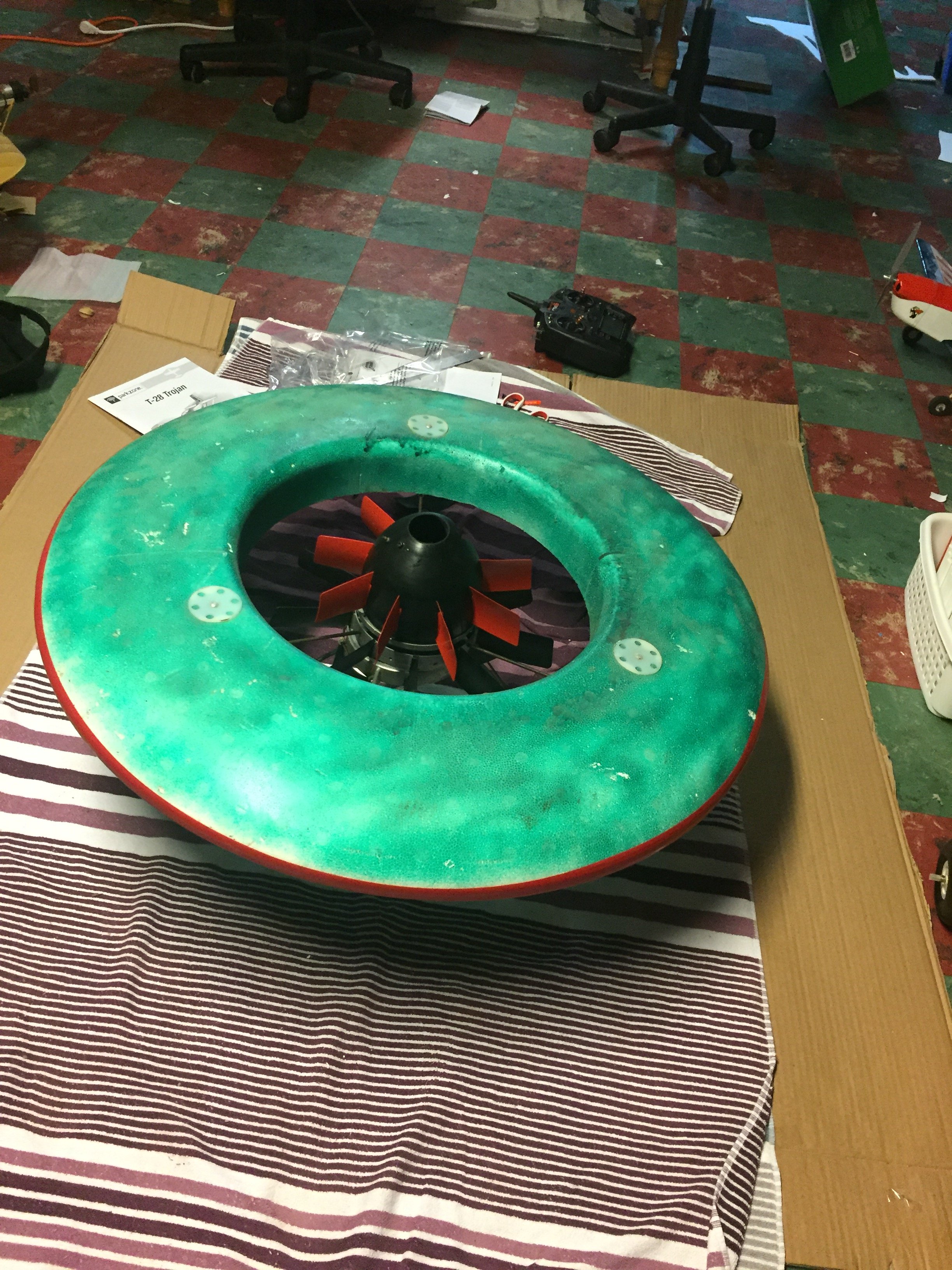
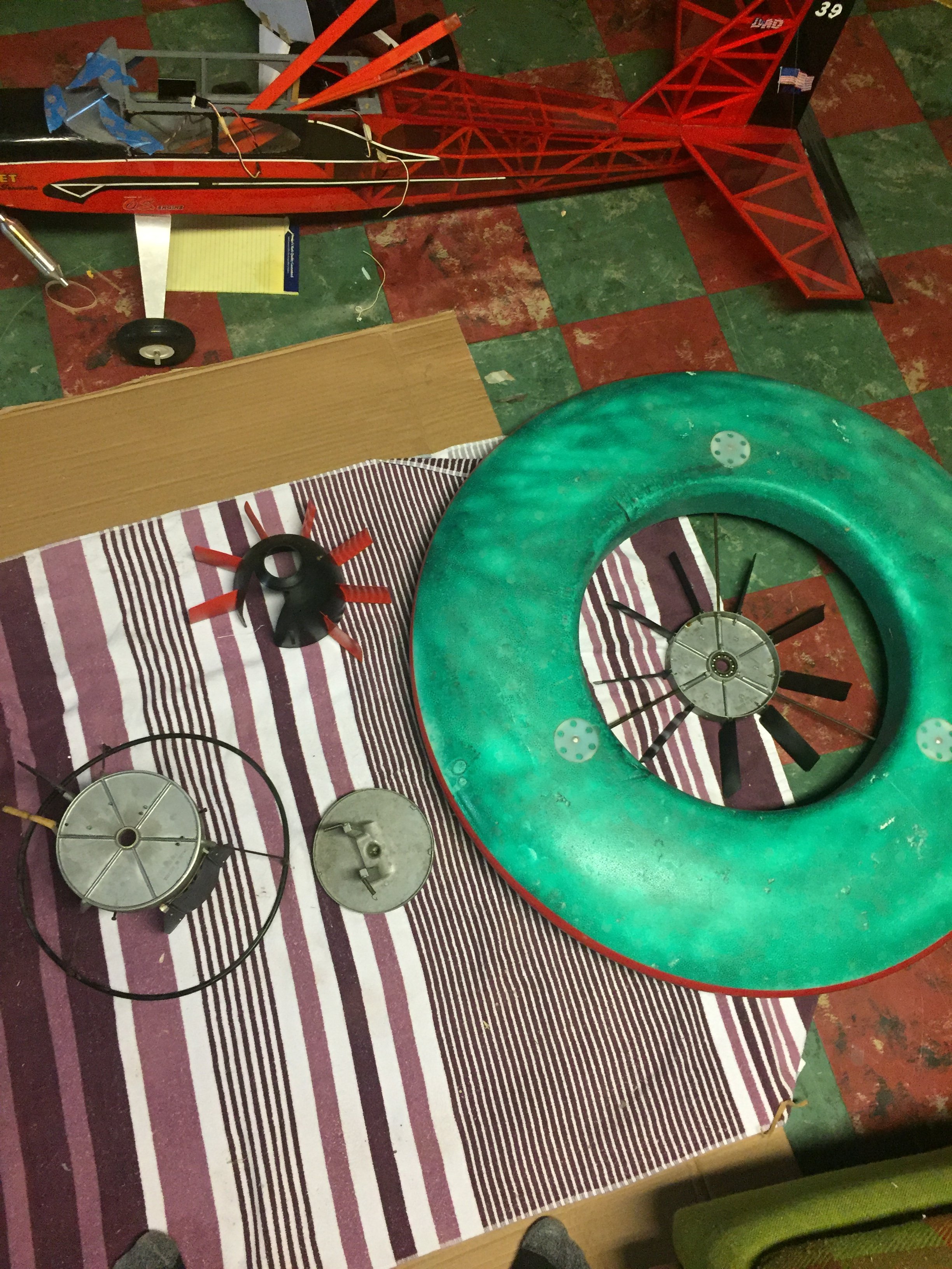
This is a bit of an oddball I came across, found it in a pile of old stuff in a trailer. Further research reveals it’s called a Turboplan, a kit from Austria in the 70s . It’s supposed to run a hot .60 vertically and the foam ring spins to provide stability (sorta like a flywheel). Anyways, I’d like to convert it to electric, and it seems simple save for the fact it has aluminum brackets for the .60 molded into the aluminum hub. Now, my motor won’t fit between them and I have no idea how I’d mount it to the brackets. If I shave them off and bolt it directly to the plate, then the motor won’t stick out of the cowling. Any thoughts or ideas would be much appreciated.
21848A40-388C-4504-8AE6-6648974D8B27.jpeg
6C6C2285-A48B-474A-B1F4-ED86AC4E7A21.jpeg
B61A1207-1482-4BB0-AF75-0BCB9A440A2D.jpeg
5C959FD2-D89E-4FEE-87AB-A3951A78F6AD.jpeg
CF2F64DA-E87A-4CC9-B232-443A4C7E344E.jpeg
 

Chuppster

Well-known member
First off, this thing looks crazy!

Second, isn't the conical black/red thing missing some fins? or is that stationary and the black fins rotate?
 

mrwhiskers

Ludicrous speed, GO!
First off, this thing looks crazy!

Second, isn't the conical black/red thing missing some fins? or is that stationary and the black fins rotate?
The comical black thing is the cowling, and those blades are stationary. Propellor sticks out the top of that apparently. The black ones are connected to the rotating part of the hub and the prop blast makes them rotate, which spins the outer foam ring

If you search Turboplan RW80 on google you’ll find a few others that are around
 

Hai-Lee

Old and Bold RC PILOT
From your description I assume that the motor selected has an external diameter wider than the mounting arms used to support the original motor installation. Based on that assumption I make the following suggestions!

You could "Shave off the original mounts and fit an aluminium box mount for the electric replacement to give the correct mounting height.

You could make an alternate mounting plate from sheet aluminium to replace the original mounting plate and mount the aluminium box mount on the fabricated plate thereby allowing the original engine to be refitted if the conversion is to be reversed.

You could make a replacement mounting plate from Carbon fibre with a mounting block integral to the piece.

Of lesser value but greater engineering input you could fit 2 smaller diameter motors and connect them in mechanical series but then the height might be too great though you could organise to mount them between the existing mounting arms.

It all depends on what engineering facilities you have access to and how much you wish to invest in the project!

Have fun!
 

Chuppster

Well-known member
From your description I assume that the motor selected has an external diameter wider than the mounting arms used to support the original motor installation. Based on that assumption I make the following suggestions!

You could "Shave off the original mounts and fit an aluminium box mount for the electric replacement to give the correct mounting height.

You could make an alternate mounting plate from sheet aluminium to replace the original mounting plate and mount the aluminium box mount on the fabricated plate thereby allowing the original engine to be refitted if the conversion is to be reversed.

You could make a replacement mounting plate from Carbon fibre with a mounting block integral to the piece.

Of lesser value but greater engineering input you could fit 2 smaller diameter motors and connect them in mechanical series but then the height might be too great though you could organise to mount them between the existing mounting arms.

It all depends on what engineering facilities you have access to and how much you wish to invest in the project!

Have fun!
And, if you have a 3d printer, there's always that!