Powering a FPV camera from the AUX of a distribution board?

regred002

Junior Member
I am new to using FPV and I would like to know if there is a way to step down the aux output of a power distribution board to be able to power a small fpv camera

here are the exact parts I am using if that helps:
Camera : Spektrum VA1100 Ultra Micro FPV Camera
Requires : 3.3-4.3v to power it (1 cell liPo) and 300ma
Battery : Turnigy 2200mAh 3S 20C Lipo Pack
Output : 11.1v and ????a
Power Distribution board: Quadcopter Power Distribution Board XT60 XT-60 20a Quad Mutlicopter 3.5mm
Just a simple board with a simple aux output

is there a way to step down the voltage so I don't have to use an external battery to power it? and will the amperage affect the camera in some way I should know about?
 
Last edited:

Avaviel

Member
If I'm reading it correctly, the pins need to have a BEC soldered to it. Or the BEC power (Not battery, lol) from your ESCs should be soldered to it. The pictures on Amazon seem small.

And this board does not look to have a BEC, eother.
 

MototechRyan

Wannabe Jedi
There's also the option of adding a second battery. A small 1s dedicated to powering your Spektrum cam.

All of the PDBs I've used have had provisions for a pololu circuit. I.E. four holes to solder whatever voltage pololu board you want to use to it.
 

regred002

Junior Member
I don't have a pre-distribution board BEC, My BECs are part of my ESCs. as I understand you link up the PBD to the ESCs and the ESCs motors. Then the 4-pin leads from the ESC's to the flight controller.
 
Last edited:

Avaviel

Member
Then.... Ok, honestly, i'm unsure of how this is supposed to be exactly.

IMG_20151130_230116 by Avaviel

I'm ignoring the normal power to the ESCs for this diagram. S is the singnal wire, and the + and - are the 5v from each BEC on all of them. On the KK2, you aren't supposed to attach all of the wires, just the positive and negative from ESC#1, and then the singal wires from all motors. BUT I also read that not connecting the negatives can lead to desyncing, something I think I've experienced.

So. The question is this: Should all of the BECs be combined into one to power items, or should it just be one and combine all of the negatives?
 

trevoof

Member
I am new to using FPV and I would like to know if there is a way to step down the aux output of a power distribution board to be able to power a small fpv camera

here are the exact parts I am using if that helps:
Camera : Spektrum VA1100 Ultra Micro FPV Camera
Requires : 3.3-4.3v to power it (1 cell liPo) and 300ma
Battery : Turnigy 2200mAh 3S 20C Lipo Pack
Output : 11.1v and ????a
Power Distribution board: Quadcopter Power Distribution Board XT60 XT-60 20a Quad Mutlicopter 3.5mm
Just a simple board with a simple aux output

is there a way to step down the voltage so I don't have to use an external battery to power it? and will the amperage affect the camera in some way I should know about?

I'm not sure about the specs on your power distribution board, but you will need a step down regulator (https://www.pololu.com/product/2851) if it does not have a BEC in the AUX circuit (are there any capacitors/inductors on the PDB?).
 

trevoof

Member
I'm ignoring the normal power to the ESCs for this diagram. S is the singnal wire, and the + and - are the 5v from each BEC on all of them. On the KK2, you aren't supposed to attach all of the wires, just the positive and negative from ESC#1, and then the singal wires from all motors. BUT I also read that not connecting the negatives can lead to desyncing, something I think I've experienced.

So. The question is this: Should all of the BECs be combined into one to power items, or should it just be one and combine all of the negatives?

For powering the Flight controller, the recommended way is to only connect the the positive and negative from one of the ESCs. But please also refer to Craftdan's comment in this post: http://forum.flitetest.com/showthre...ricopter-Build&highlight=electrohub+tricopter

From an electrical standpoint I've ranted about this before, and recommended people pull their power leads from the ESCs, and seen several others argue this practice with both switching and non-switching regulators . . . but one piece of evidence I must admit I've yet to see: failures.

Gotta admit -- this bugs me.

I simply haven't seen it on any of my builds where I've neglected to do it. I simply haven't seen anyone complaining that their UBECs have failed.

In the end, it's not the same as connecting two un-tuned regulators right next to each other -- these should be tuned to the same voltage, and the resistance in the power lead and the load from the FCB can provide a mechanism for any slight variation to be balanced, and give isolation for the regulator's feedback loop.

If someone has evidence to the contrary, I'm curious to see it. I know the theory, but if it's sound, reality should match.


I don't think it matters whether you connect up the rest of the negatives - they all share a common ground back at the battery anyway.
 

trevoof

Member
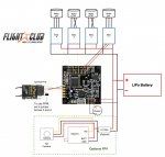
Here's a nice wiring diagram from FPV light Club (http://fpv-flightclub.com/how-to-build-fpv-quadcopter/). Its for a NAZE32 board, but the idea is the same.

FPV-quadcopter-build-schematic-.jpg
 

Tmarter

New member
Or...

you could pick up one of those step-up/step-down regulator board that accepts inputs from the balance ports from a 2s-4s lipo pack. That's what the FatShark kits come with, they're about 1.5"x1.5", and eliminates any connections at all, plus if you're packing stuff into a tight space and/or watching your weight, it's one of the lightest, cleanest, and easy to switch your power supply...say deciding to go from 3s to 4s, you don't need to gut the quad to switch how power is routed to the FPV gear so you don't fry all of it from over-voltage...Plus it even has a filter to reduce noise in your vTX signal, so you get a nice clean pitcure even though all the components are in the same circuit drawing from a single battery.

Having not realized I was actually going to buy the FatSharks myself...I made my own voltage regulator and a ferrite LC Filter to use with my old gear, then the dang kit comes with one small board that eliminated the need for everything I just made, and made it way more versatile. lol

I'm sure you could probably order one of those little boards individually, and the components on it are relatively simple...highly doubt it would cost that much. Plus just about all the connectors that concerns any FPV gear share the same connectors for powering the vTX and camera, if not it wouldn't be a hassle at all to switch things around.
 

Tmarter

New member
Sure, you can make a more efficient filter like the one I made, kind of a prototype i never cut down to size:

View attachment 58902

... you can add an extra battery, a regulator, etc and make things a lot more complicated, but I can say this one below is what I was talking about, and works perfectly fine... even when I'm hammering it through some decent wind (not like I enjoy it, lol). Most simple solution if you're just trying to power your gear with the right voltage, that's about as simple as it gets:

View attachment 58901
 
Last edited: