What plane should I add the Prandtl-D Wing to?

  • Mini-Arrow

    Votes: 20 37.0%
  • FT-Explorer

    Votes: 15 27.8%
  • FoamyDM-HS Carrier

    Votes: 7 13.0%
  • FT-Simple Cub

    Votes: 7 13.0%
  • FT-Tiny Trainer

    Votes: 13 24.1%
  • FT-Bloody Baron (somehow)

    Votes: 7 13.0%
  • Airliner

    Votes: 14 25.9%

  • Total voters
    54

FoamyDM

Building Fool-Flying Noob
Moderator
This is Reserved for my Attempt to build a PRANDTL WIng as featured on an FTCC when they spoke with NASA engineer. The one that flies with *proverse* Yaw


I looking into it here: http://www.amaflightschool.org/PRANDTL and https://www.nasa.gov/centers/armstrong/news/FactSheets/FS-106-AFRC.html
and of course the link of the nasa site showing the summer inters building a fiberglass one.
and looked through the White paper from NASA.

From the White Paper:
There is enough information there for anyone to build this sucker. and the AMA site as the IGS files (whatever they are)
but I took the paper coordinates and ploted it in EXCEL xy graph. and got this:
MainWingSection.PNG

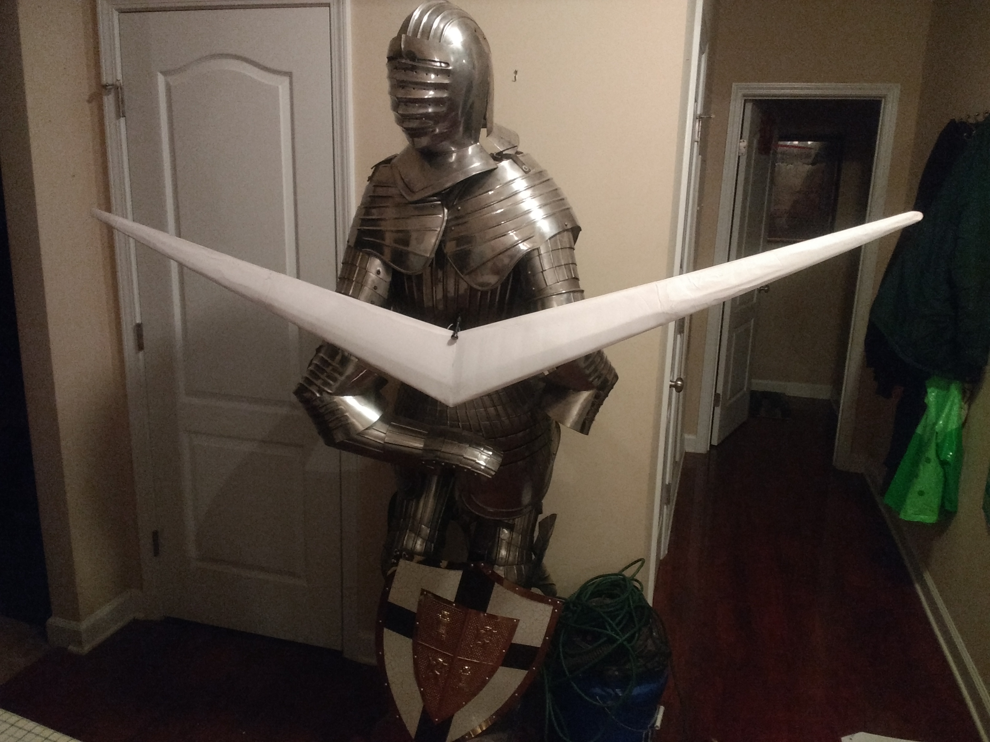
I'll continue working on the wingtip section...
4/29/19 Edit:
OuterWingSection.PNG

as you can see it is symmetrical.

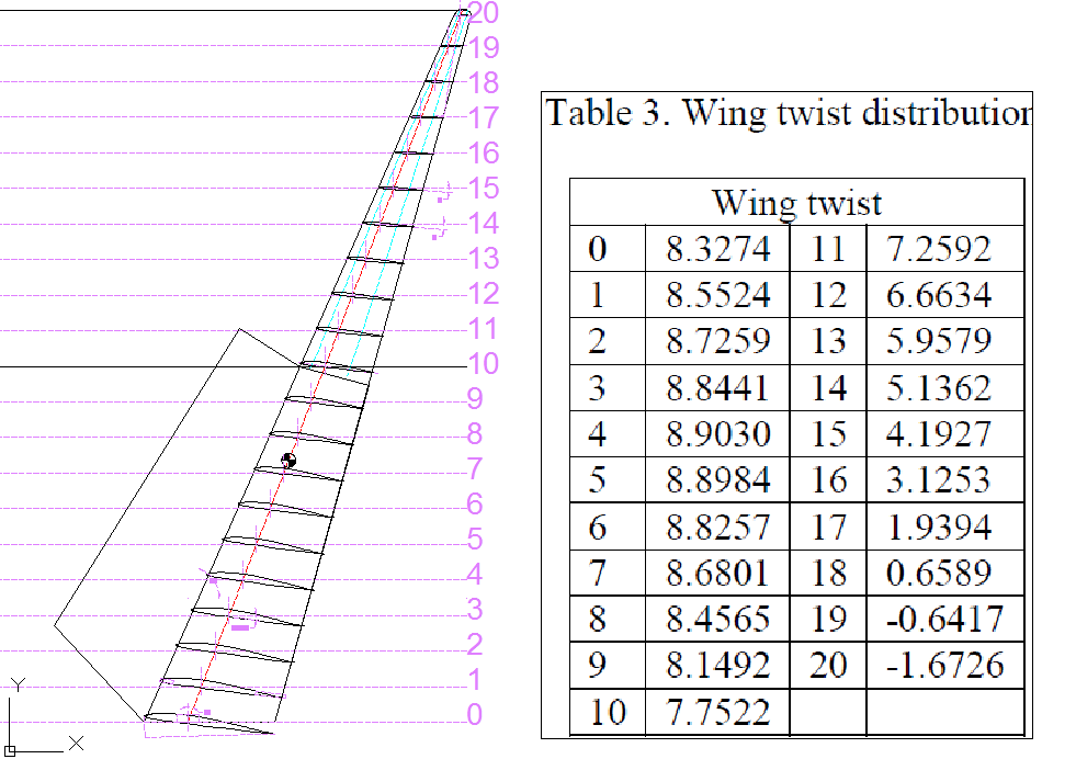
Then they have a table describing the Wing's twist over the wing length broken into 20 sections. 0 is the base 20 is the wingtip
WingTwistTable.PNG Wing Tip.PNG <-Wing Tip Config from AMA site

With a 12.3 ft Wing Span, The base is chord 15.75" and 3.94" tip chord, with a 2.5° dihedral, with a 24° sweep (<- edit 4/29/19)
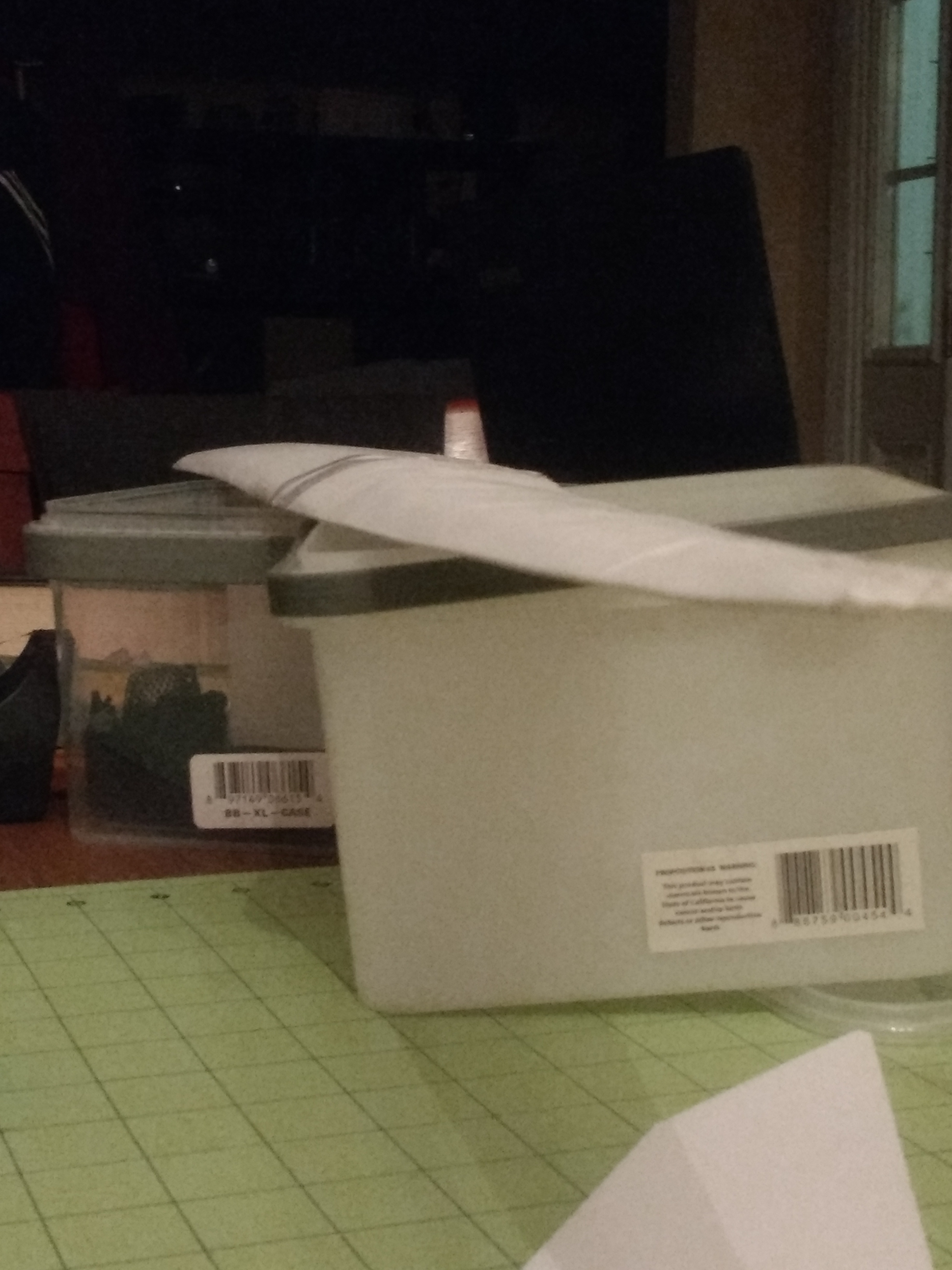
I think I will make mine 9ft. that will make each half 4.5 ft and should fit in my Toyota Yaris Trunk.

WingLoadVisual.PNG

Project Goals:
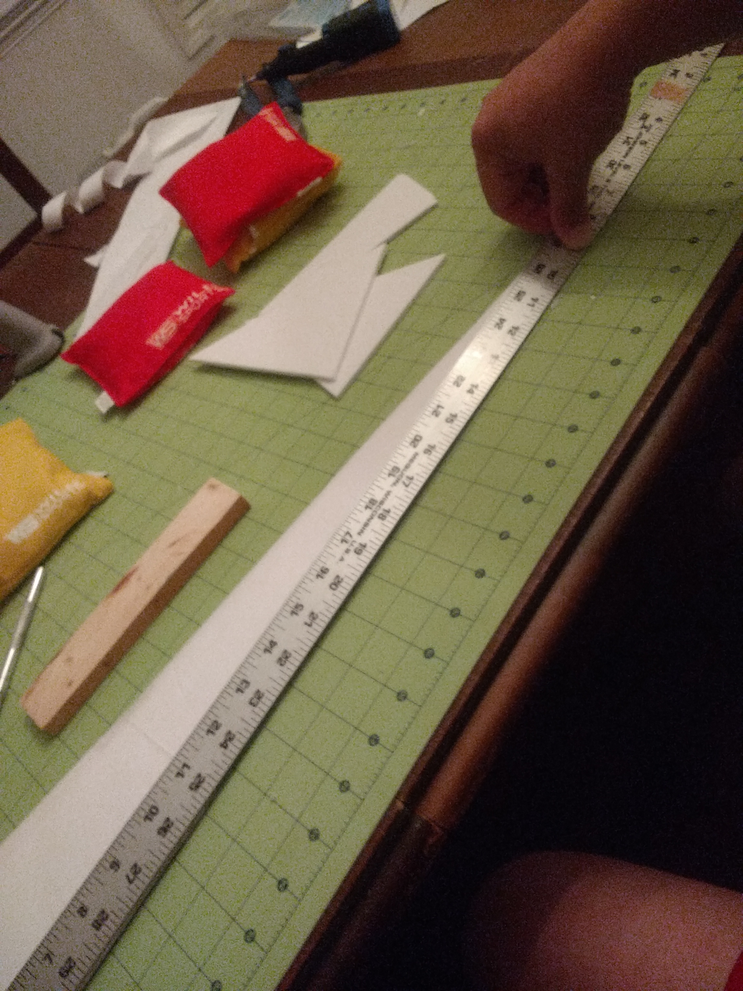
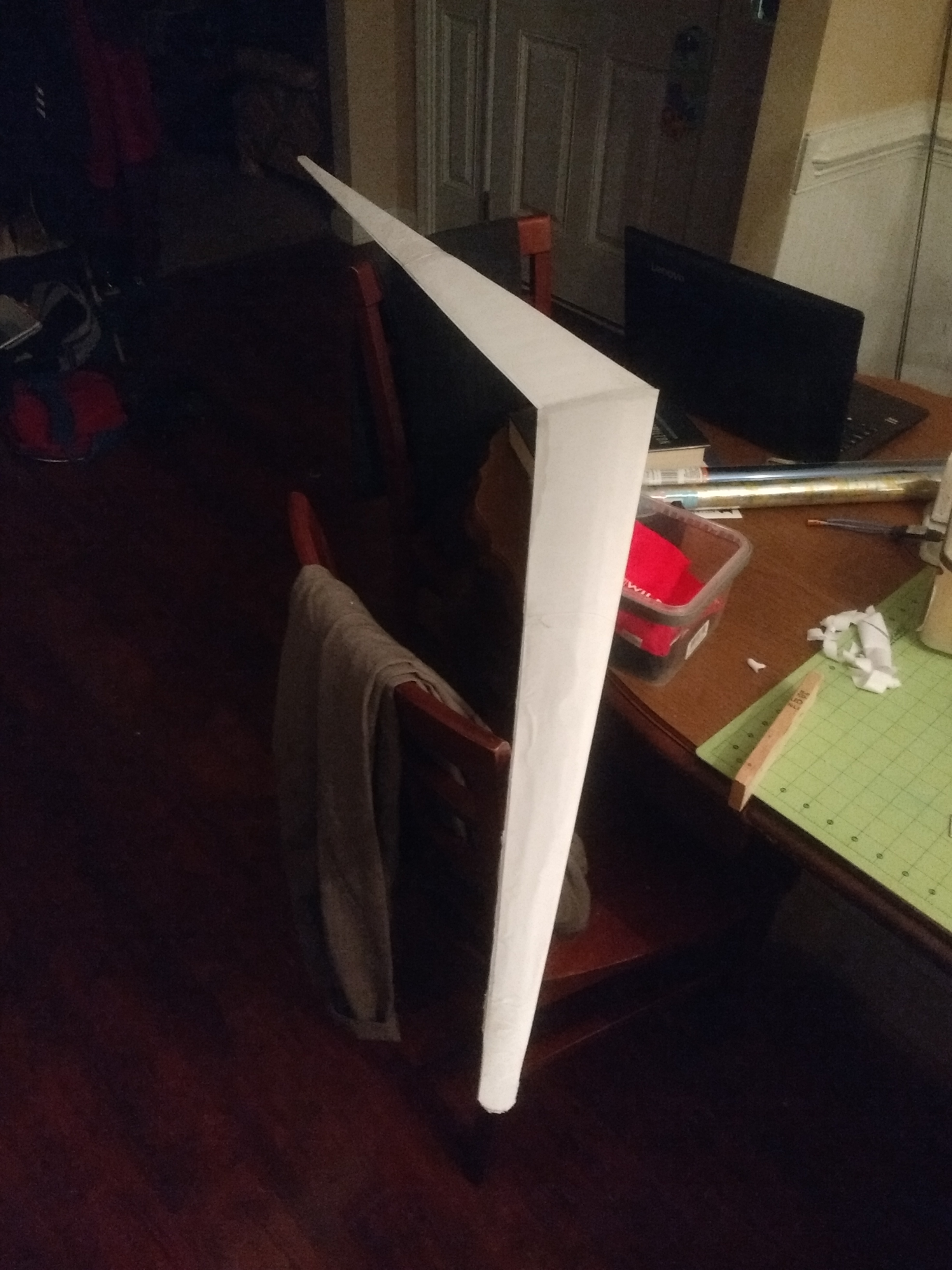
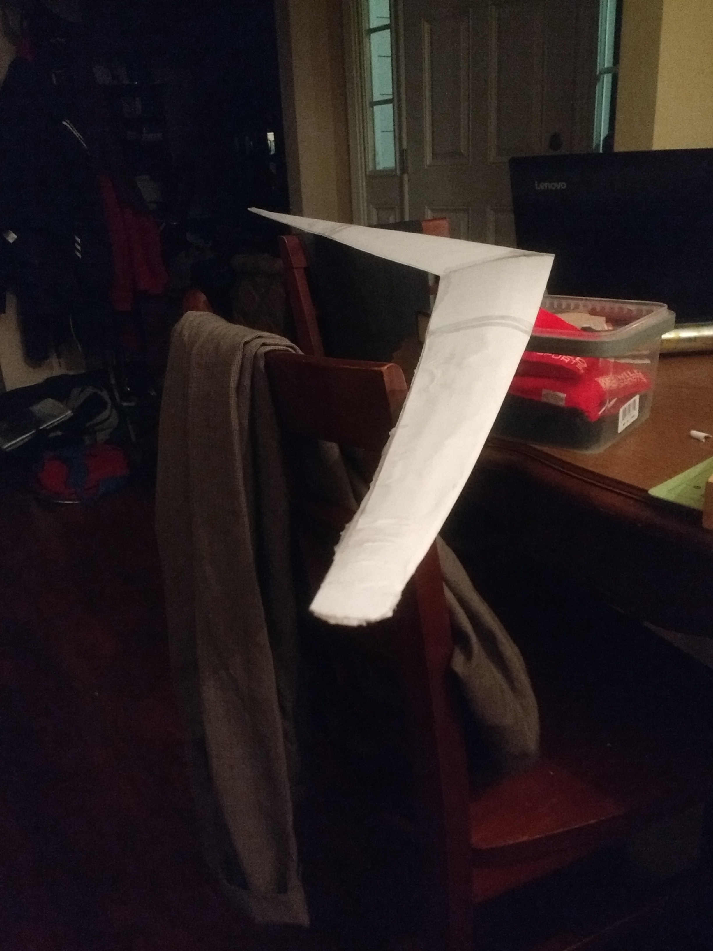
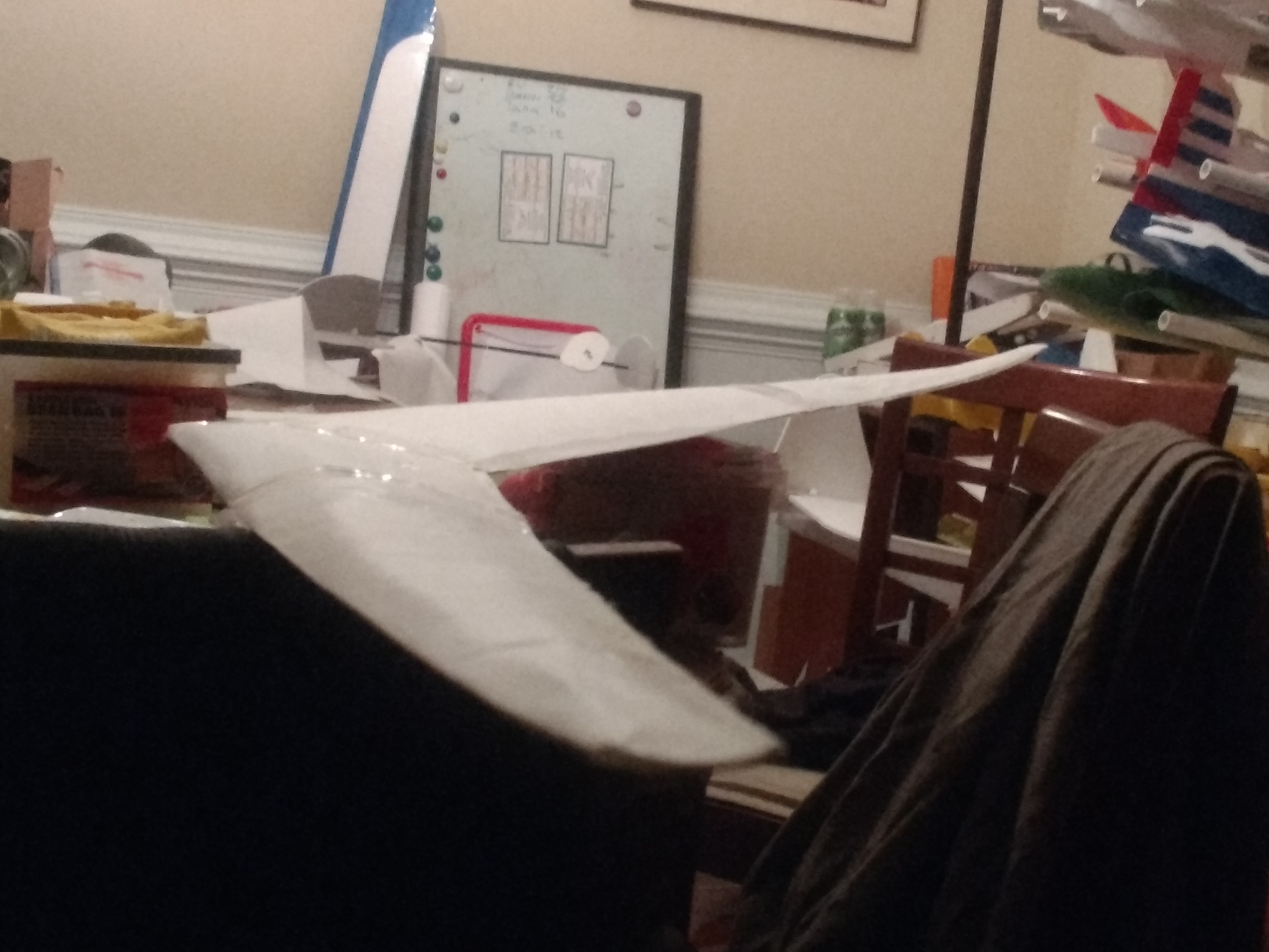
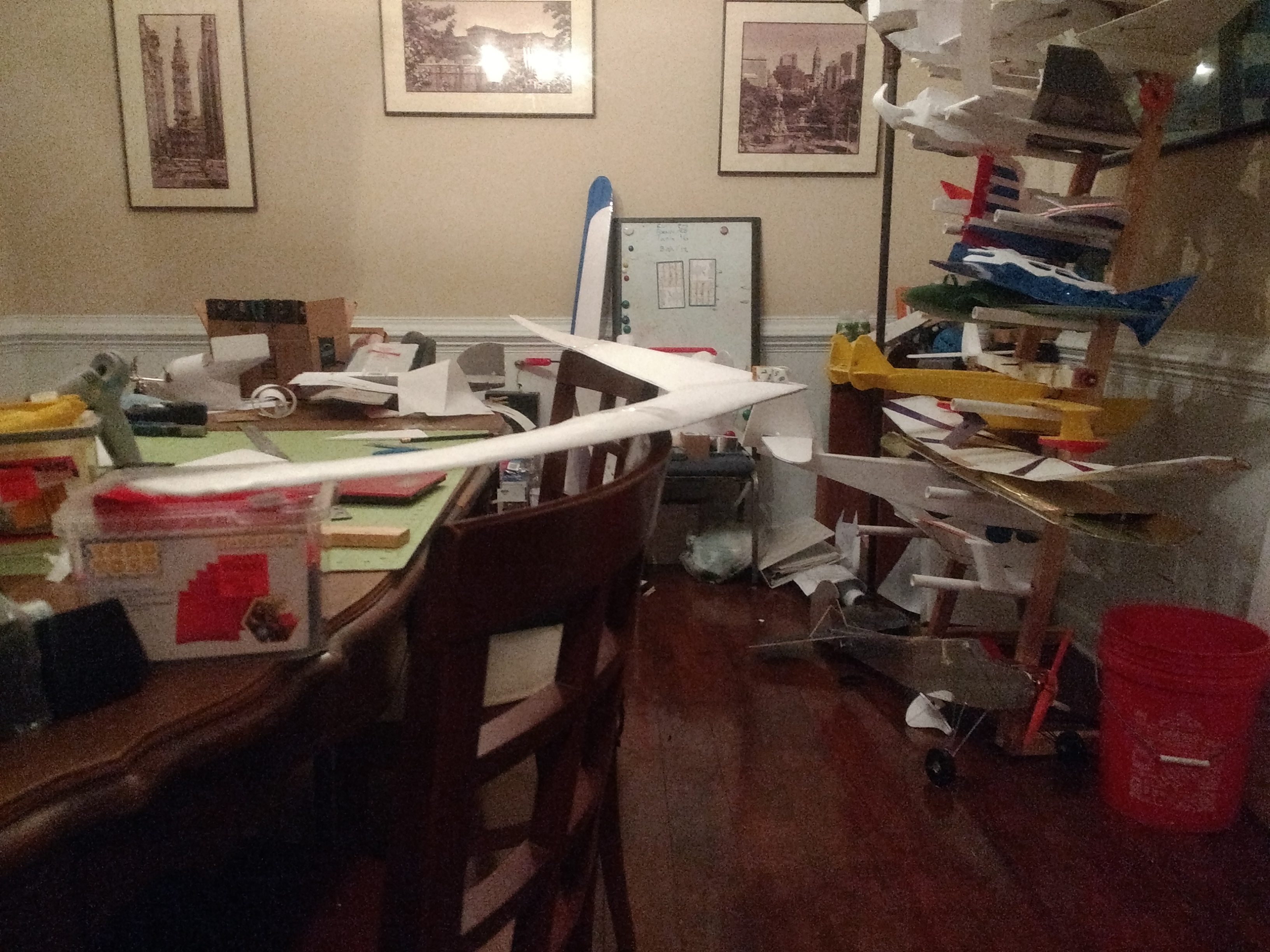
Phase 1 - Build a working version per the paper with the same wingform, and twist as prescribed using DTFB.
Phase 2 - See if this can be replicated using basic FT build technique and styling so EVERY wing lover can use it.
Phase 3 - apply it to other planes... and remove the Vertical Stabilizer
 
Last edited:

FoamyDM

Building Fool-Flying Noob
Moderator
Phase 1 - DTFB Build

As with all things. it must have a plan. For the most part, the plan came from Nasa's White paper.
PLANS
Alpha Plan. ~72" wing span. :unsure: 
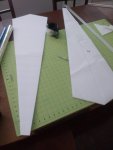
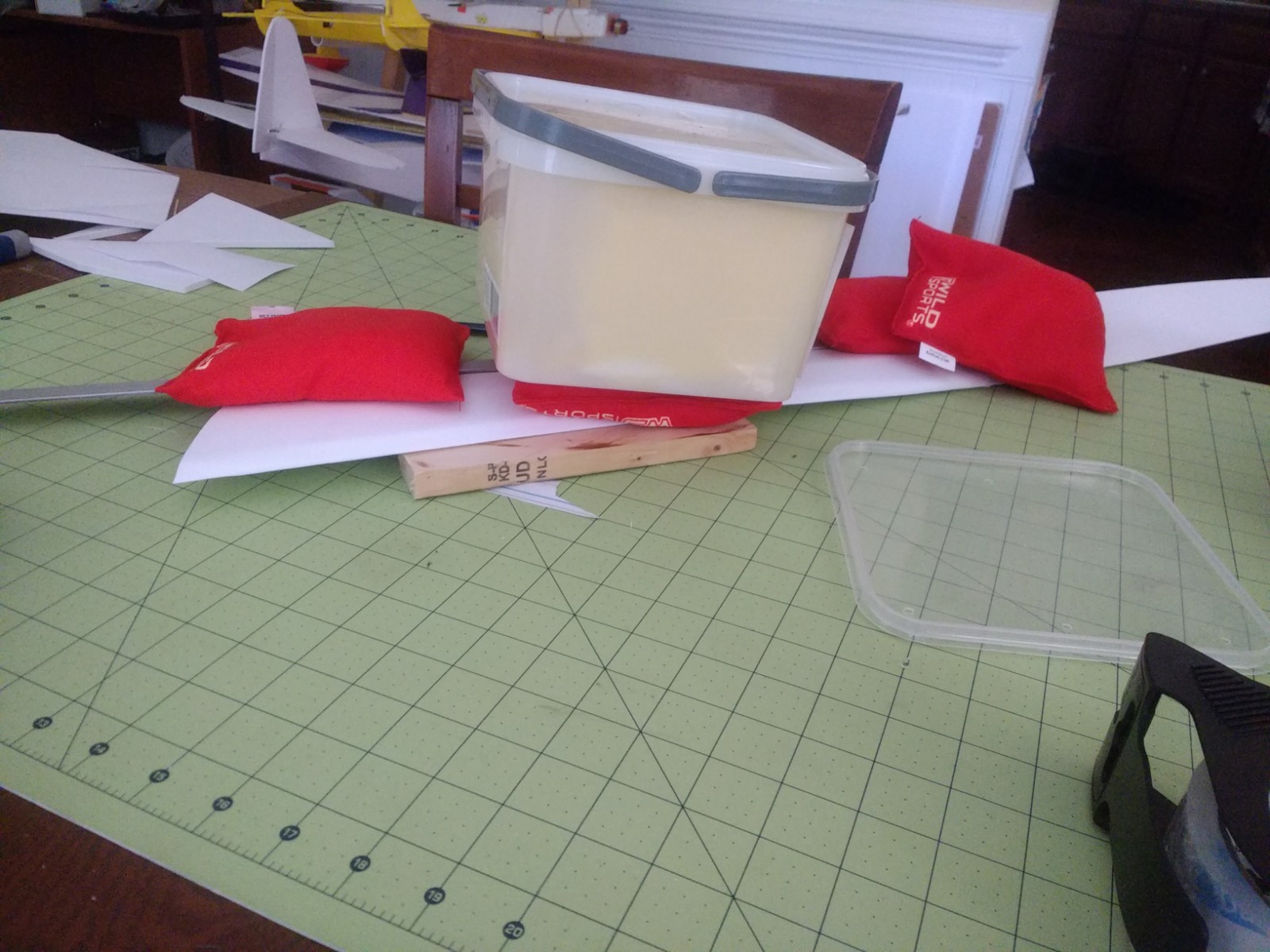
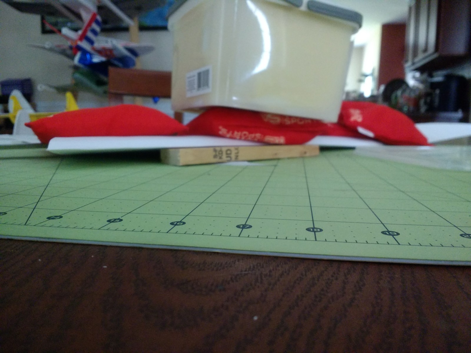
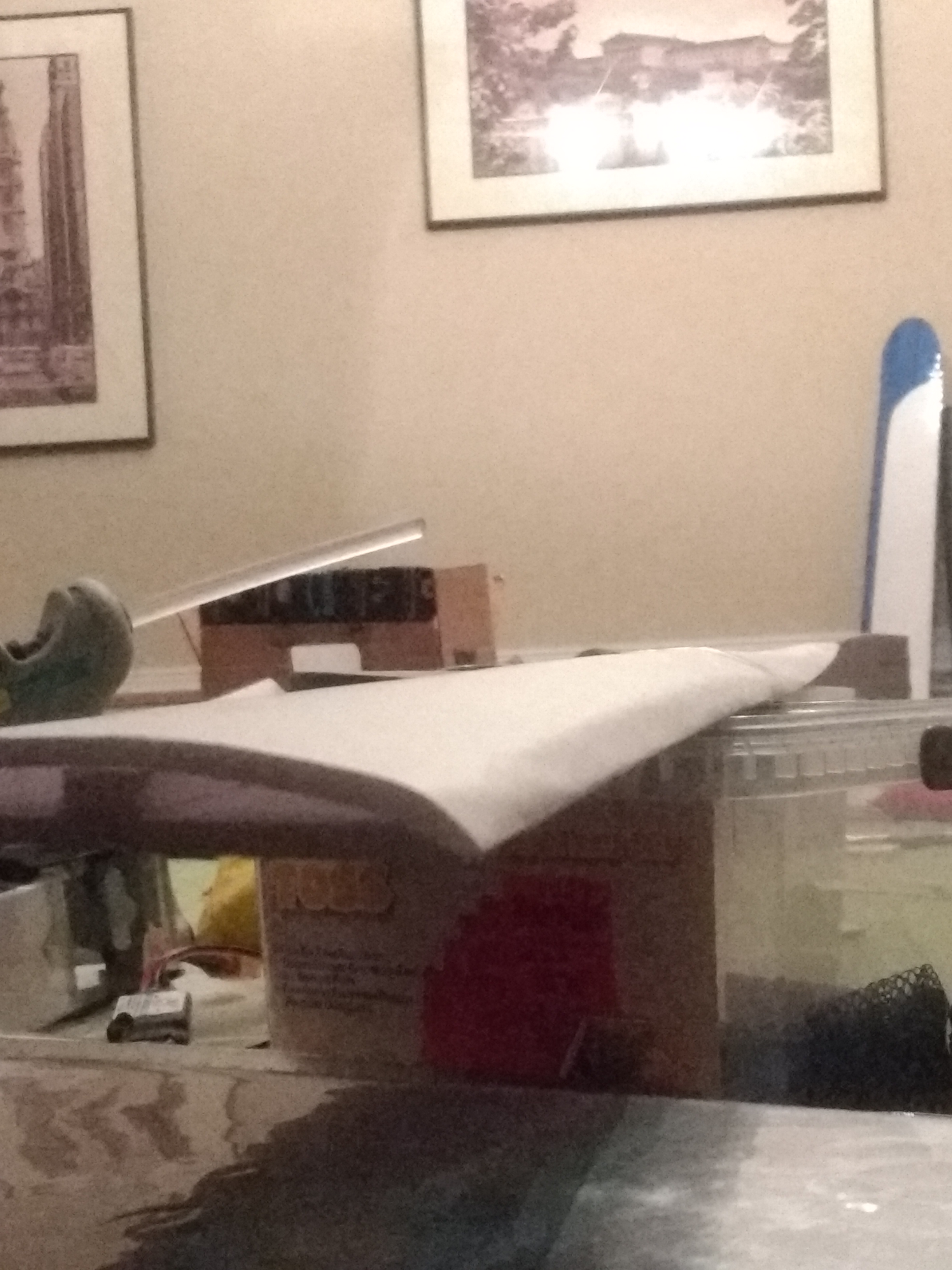
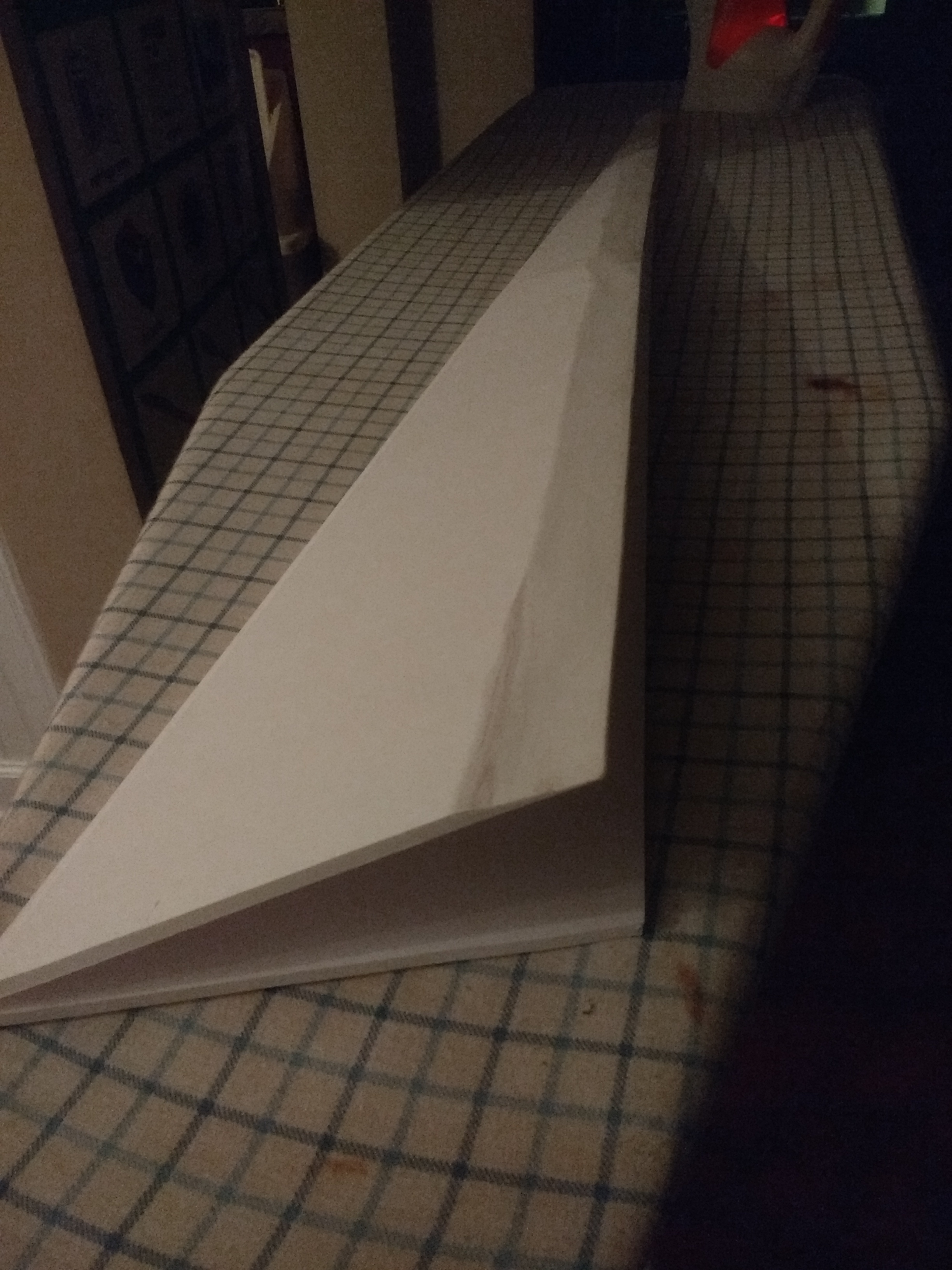
transport will be difficult, Maybe. Shaded parts are an ironed taper.

Note - the CG Marks too far back by 0.89" (7/8", 22.5mm)

THE BUILD
5/6/19

I began cutting out my print of the design... the thin strips are spars. The build methods are to iron the edges top and bottom. and on the top, remove all the paper, except a tapered strip along the guide line where the spar goes, (from 1" to 1/2")

While getting this started I am also pursuing a more traditional build method similar to Balsa. As a different way to ensure proper twist.
While I do that I will try the Balsa model approach too. working that out now...
That will likely end up as a couple sheets of letter sized paper, cut two. with a leading edge profile, and trailing edge profile...
still working out spar material - right now, yard stick seems right.
227404_f33fc9b0c7dd02996703bee188bca4e1.png

5/7/19
I started gluing it up this this morning, and ran out of time looking for my glue sticks. (it was supposed to take 2 minutes. :mad:) I finished the inner half, I used an aluminum ruler to help cool the glue faster.
227504_4a4da824a48f6c72ee28d4aeea0dcabf_thumb.jpg

227510_8f7ac226782a54afac5714761a53acfa.jpg


5/8/19
I found my glue stick nest... And got to working.
227610_140038801b2977976effdf77d3ed0d40.jpg
227616_a1811fc25a9ccb89d745deb3f166add0.jpg

Note the curve and the bump in the leading edge.


Then I got to work on the other half:
227612_993322d4ec4fd123e4bcdb5c008e242c.jpg

227614_b9947ebdf4a0a66e3ccc373b036da39d.jpg


The I put them together, and viola!
227612_993322d4ec4fd123e4bcdb5c008e242c.jpg

227614_b9947ebdf4a0a66e3ccc373b036da39d.jpg

227618_9938731b1466560f1703c76e75daf4e6.jpg

227622_5be826567ebccf59de3d3d0064a3fc76.jpg

227626_6a3ab4ac9097a9f702976797167bd1f4.jpg

227630_9f80b6c3d72912f751807cd8f192b63f.jpg

227632_fcee0e5a7b14a31bb60849df92d14bda.jpg


How I got the Curve:
The Key is the 1/2" wood block. and hot glue being hot, slippery at first and sticky.

For the twist to occur, the front edge height as it tapers goes from 1" at the base, to 1/2" at the first segment then the second segment stays near that 1/2" for the inner 1/3 of the outer Segment. the end is Flat. The build Process is get the inner segment glued up, line up the rear edge the front edge supported as described. weight it down, pressing the rear edge closed which is flat against the table.and wait for it to fully cool. (heat sinks, like the ruler help). then do the other section. which is 50% two sheets direct pressed, creating a shear surface rigidity. but as it is rubbery glue there is flex. (I suppose gorilla glue might be stiffer.


This is where I need to quit...
I started measure in balance spots and weight.
View attachment 130748
Tradition is I go fly it in the front yard... In the dark...
It will wait. It is one piece of DTFB with almost no waste. So... ~100g estimate?

Here my video test of the rigidity. Stiffer might be desired. But we shall see.

Back to the beginning.... I wait. And done't be a fool.😜

5/9/19
I had very little daylight minutes to test this yesterday. Balanced at the plan CG marks with 21g (4 quarters) at the pencil mark ~1" from the nosetip is much to tail heavy. It looped nearly immediately.
so I added more weight. about 11 grams (2 Quarters) and another go.. push- curve up-stall. I'm close. add more 5g, and push it up. to the nose tip.
Now it flies! something isn't symmetrical. it consistently turns left. (Of three balanced launches).
my launch was more of a dart toss at the rear apex (where I would put a motor mount.)

Based on those three tosses I learned little. BUT, of those I learned it Yaws left as well - PROVERSE YAW B!TCHES!

More tests coming. And video.

Later that night - next morning
I did my glide test now, I put 40 g of coinage in the very nose of the plane and had it glid very well at this point it's probably just a variation of a couple grams to make it optimal I noticed that when it would Bank it would also proverse yaw even if it's just a little this point which is spectacular!

Take a look for yourself:

On a decent dart toss. It traveled clear across the lot. ~100'/5' drop = 20:1.

5/10/19 - Daylight Tosses
I think I could use *just* a little more weight: 2.5->5g
Last night it hit the garage and bent. you can see crease at the very end.
 
Last edited:

FoamyDM

Building Fool-Flying Noob
Moderator
Phase 2 - Prandtl - D using Master Series and Traditional FT build style
IMG_20210605_184139314.jpg
Since I have experienced the failure. for the success and failed motorized attempt (see above) I have been thinking 'bout when I would be getting back to this project.

over the last two years many others have managed creating various forms of this craft as a glider or a 3d printed plane and been successful.
Through the Aviation RC Noob Podcast, Joe and I have chanced to have a great interview with Red Jensen (Episode 25, Episode 26) who was a chief pilot over much of the Prandlt-D project headed by Albion Bowers. As we prepared for the interview, and doing research about the Neil Armstrong Research Center I saw Different versions so I took a moment to create a simple modification of the plane to change the planform, but not the other key elements.
2-sheet - nearly no waste
The new plane is un-wasted sheets of DTFB. cut longways from 8" to 12" from one side. Then cut off a 1/2 strip from both sides. to build a spar. This allows the construction of the wing half.
The important piece to this puzzle. is how to Place the spar, and how to shape the trailing edges of the wing halves. It is important that the inner section functions like a modified Clark Y, and the outer like a Symmetrical wing, with a twist from +8° AoA on the inner section, and it twist to a -2° AoA at the tips.
IMG_20210605_184129615.jpg
Spar line
The spar line on the bottom of the wing should be from ##" to ##" at the wingtip
IMG_20210529_145619344.jpg

On the top it must be moved back a 1/4" on the wing root and remain at ##" at the wingtip.
Trailing Edge
Outer edges
The trailing edge treatment is also important. the outer half must bevel the edge in 1" from the trailing edge insides, top and bottom.
Inner Edge
The top must have the trailing edge beveled 1" in along the inside trailing edge, like the outer half.
The bottom of the must have a 1" bevel on the outer side of the trailing edge (not the inside), opposite the outer wing half.
IMG_20210529_145628930.jpg
Glue-up
The last key bit is the trailing edge of the root half top sits on the bottom ~1/2 to 1/4" from the TE. and fairly constant for the inner half of the wing. this then transitions to matching trailing edges for the outermost wing quarter to the tip.
The key to this and getting the twist, is to put the wing flat, place a ruler under the trailing and lift the Wingtip 1 3/8" at the tip TE, while keeping the front tight against the build surface with weights. (such as bean bags, rice, or shot), It is VERY important to let the glued cool completely before releasing the weights. (10 mins. min.)
IMG_20210529_164116975.jpg
Symmetry
Do the same but mirrored to the other side.
It is important the section is symmetrical airfoil at the tips and 10° angle from the table on BOTH WING HALVES.
IMG_20210529_145340881.jpg IMG_20210529_145432596.jpg IMG_20210529_164116975.jpg IMG_20210529_145555755.jpg IMG_20210529_145703125.jpg
Once completed the wings can be joined, and glued together. If you are concerned about strength, imbed a 10" BBQ skewer in an 1/8" wide track glued in directly over the spar. ensure glue setting before moving on (10 min.) and put a piece of tape from wingtip to wingtip.
Control surface should only be on the outer 1/8 to 1/4 of the wing. as this is where the twist coupled with surface deflection of a roll will yield the forward lift, and thereby the proverse yaw, which allows for no rudder.

Electronics Location
Once the body is build and the Control surfaces are place. I used a 9g servo placed in front of the spar at the inner edge of the Control Surfaces.
The Motor Must be mounted at the back edge of the wing so to have a 10° with the Top of the Wing.
IMG_20210531_161357489.jpg
There is also and optional Battery and FPV pod to attach to the bottom front of this. [plans pending]
1644524112092.png 1644524149796.png 1644524181273.png
Weight
Base Weight: 230g
IMG_20210531_003510080.jpg
Dry weight: 360g
AUW: 645g
SPECS:
winspan - 60"
WingChord - 12"
Motor: 2306 1700kv Emax ECO
Esc: 35A 2-6S opto (with Separate BEC)
Prop: 6"x3"
Battery: 2200 mAh,
Ballast: 1300 mAh
2-9g Servo with 20" leads
IMG_20210605_184155724.jpg IMG_20210605_184145324.jpg IMG_20210605_184133430.jpg IMG_20210605_184139314.jpg

PLANS
1623101733789.png
Beta Version Plans Link

Glide Test

Maiden Flight and Proof of Concept

A Graceful 2nd flight Video:

Another Flight Video
 

Attachments

  • DTFBPrandltD.pdf
    494.5 KB · Views: 0
Last edited:

FoamyDM

Building Fool-Flying Noob
Moderator
Phase 3 - Apply to other planes
Prandlt-Arrow

I had a little bit of time, and I realized I could make an Arrow size/shape Prandtl wing, as per Popular Request. This design (from Post #3 scaled down 2/3rds and now nicely fits to one sheet with it's 36.5" wingspan, could be a ~250g flyer if you wish it to be. (with diligent building weight management & power system weight management).

Specs
36.5" wing with 23° sweep

2204, 2300kv motor
30a-40a ESC 3-6s
1300mAh 3s - 850mAh 6S
5x4.5x3" Propeller
2 9g servos (5g will work too)
you may need 2x Servo extensions

1806 2300kv motor
12a-ESC 2-3s
450mAh 3s, 650 2s
5x4.5 3s, 6x3" 2s Propeller
2 9g servos (5g will work too)
I will put a tongue depressor on the bottom, and line the tip with the nose, to protect from harder landings.


PLANS
I chose to move the motor mount closer to the CG of the model to allow me to reduce the nose weight needed. to keep the pod impact/drag small, I turned it vertical.
FDM-Prandtl-Arrow.PNG
This goes together well, but has been quite the handful to fly. If you want to build, please do. if you do, let me know your experiences.

Build Log
I had a little bit of time today, and I realized I could make an Arrow size/shape Prandtl wing, as per Popular Request. This design scales down and nicely fits to one sheet and is 36.5" wingspan, could be a ~250g flyer if you wish it to be. (with diligent weight management & and system management).
Step1 - print and mount for cutting
IMG_20211110_090247185.jpg
I expect this goes together almost identically as the larger straight wing in POST #3, the difference is arrow size and the 23° sweep of the wing. The construction is the same. taper the trailing edges in the same way, and fold over in the same way, using the twist guides, glue and weigh it down. A key piece is to be sure the twist in each wing needs to be symmetrical. This flies off the same system or using a smaller 1806 with a 12A esc, but should fly much faster. I suspect orientation markings will have a big impact on visibility.
Step 2 - Cutting
Taking 30 mins at the witching hour last night, I
IMG_20211111_004608909.jpg
IMG_20211111_004540814.jpg
After I finished cutting, before I called it a night I thought I should see how it weighed in.
IMG_20211111_004858803.jpg IMG_20211111_005117733.jpg
based on what I am seeing here, 92g in foam, and 96g in electronics, I have 61g to spare and still keep it under ~250g. It will be a challenge, but it should be possible. FPV would be a BIG plus here So I plan to put it in.

I am wondering if the A- pack motor package (1806 with 12A esc will save much weight.) 18g Motor, (11g esc, 5g prop, 42g) 77g for 1/2 the thrust (still enough to fly). As I don't care about the weight specifically... I will use the larger motor for now.
Step 3. Build it
It turns out I was not able to take many pictures. because I chose to film the build of this bird.


Here is the finished product though
IMG_20211119_133946597.jpg IMG_20211119_133921626.jpg IMG_20211119_133903286.jpg
Out to the field we go. The maiden was at the middle school
IMG_20211119_140739249.jpg

Later I tried it it at the big field. This is after a very sketchy 6ish minute flight
IMG_20211126_170656220.jpg
IMG_20211126_170700677.jpg
From here I then took it out to the field with a 1300 mah 3S. I put up against the spar tip at the nose. This was flyable, but a bit too heavy. It turns out a 1100 2S was better suited.
 
Last edited:

FoamyDM

Building Fool-Flying Noob
Moderator
This is the outer wing section as per the white paper.
OuterWingSection.PNG

I thought I had covered it above, (and will add it). There is a 24° sweep of the wing. with the controls in the outer 14% of the wing at the rear 25% of the chord. (see diagram above).
 
Last edited:

FoamyDM

Building Fool-Flying Noob
Moderator
While I do that I will try the Balsa model approach too. working that out now...
That will likely end up as a couple sheets of letter sized paper, cut two. with a leading edge profile, and trailing edge profile...
still working out spar material - right now, yard stick seems right.

WingSectionsWithTwist.PNG
 

FoamyDM

Building Fool-Flying Noob
Moderator
Me too. I was planning on building a 1 in step to rest the front edge, the tapers down to a 1/2 inch for that inner section, and then twisting the end flat to the table that should create pretty close to the same twist. I know it's supposed to be parabolic but my thought is if I can get pretty close and make it consistent on each side with the last 2" are that -1 1/2 degrees I should have that proverse yaw that Al Bowers speaks about.
I suspect it will be slow. Possibly using packing tape or pins to keep it held in place once set.

At least that's for the fold-over type.
With the individual sections I was going to use a vertical spar and glue the front and back sections to it or keep them in or I'm going to do it and then with a front piece on a back piece of foam I was going to then cover it with cellophane essentially shrink wrap the rest.

As I've never done it terribly successfully it should be interesting results. The balsa guys have mastered it, I figured we should try it's in foam too.
 

wov

Member
I am very interested in the Prandtl flying wing design, but I am not convinced that foam board is the right answer to build one. Just take a look at the leading edge of the 3D model provided by NASA:
LE.jpg

It might be quite challenging to make this happen from foamboard and as far as I understand the white paper provided, this is rather important. Anyway, I love flying wings and if it works out, I will definately build one as well.
 

FoamyDM

Building Fool-Flying Noob
Moderator
I am not convinced that foam board is the right answer to build one. It might be quite challenging to make this happen from foamboard and as far as I understand the white paper provided, this is rather important. Anyway, I love flying wings and if it works out, I will definately build one as well.

@wov you are likely correct. Foam board is rigid, but it may not be enough for such a slender section, but it is the slenderness that allows it to shift once glued...
where is that model from ? link please?

I started gluing it up this this morning, and ran out of time looking for my glues sticks. (it was supposed to take 2 minutes. :mad:) I finished the inner half, I used an aluminum ruler to help cool the glue faster.
IMG_20190507_074046761.jpg IMG_20190507_082122464.jpg IMG_20190507_082146708.jpg
IMG_20190507_082159158.jpg
 

GMalatrasi

Active member
I was playing around with their model a few weeks back... Thinking of doing a 3D printed build for it later.
Models are available from one of their online papers, I looked but don't have the link saved.
 

FoamyDM

Building Fool-Flying Noob
Moderator
I was going to ask about 3D printed options...
Ask away... I will be all over it when I get to fixing my machine. You are welcome to add to the discussion.

I might use it to try my hand with modeling.

the model is on the AMAsite as IGS files.
 

FoamyDM

Building Fool-Flying Noob
Moderator
I know this sounds dumb to my brain, but has anyone 3d printed a dissolving mold scaffold for a FG or CF plane build. Like a sacrificial Foam Build?