Probably my last big Depron plane

quorneng

Master member
My Depron Airbus A350 that uses 2 racing drone motors as ducted props in scale Trent nacelles flew so well I wanted to try something even bigger before my supply of 3 mm Depron dried up completely.
I was attracted to the Antonov AN124.

AN 124.jpg

Bigger than the C5 Galaxy and second only to the one off AN 225. I have even see one fly overhead. It leaves quite a noticeable smoke trail!
With a limited Depron supply this build would have to make full use of printed parts ideally so that Depron would only be used for the skin even then there is likely to be quite a lot of it.
With the same RS2205 drone motor driving a 4 blade 5x3.5 prop as I used in the A350 this set the size of the engine nacelle. Scaling the airframe from that gave a span of 2.5 m and a fuselage nearly as long. A big plane to be built from 3 mm Depron. o_O
As the engine nacelle set the scale it seemed logical to do that first.
It took some time to design in CAD but at least it was going to be repeated 4 times.
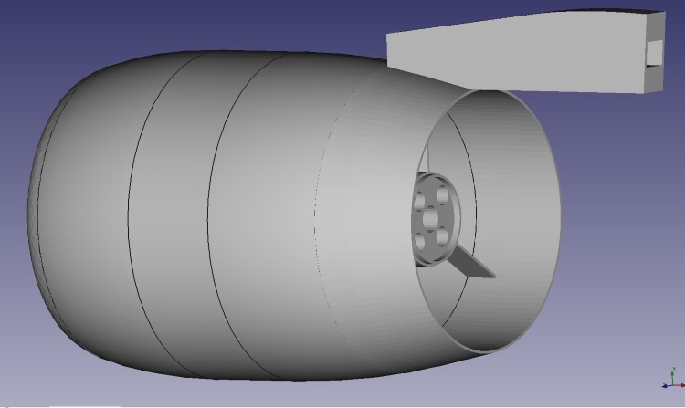
TestNacelle1.jpg

As the success of the nacelle and pylon determined whether it would be practical to proceed any further quite some development was undertaken to give the lightest possible structure as well as testing to determine how much (or little!) thrust would be available.
Eventually the nacelle was printed in 5 parts glued together as the internal structure of each part would be significantly different to suit the loads imposed on it.
A complete nacelle fixed on a vertical test stand.
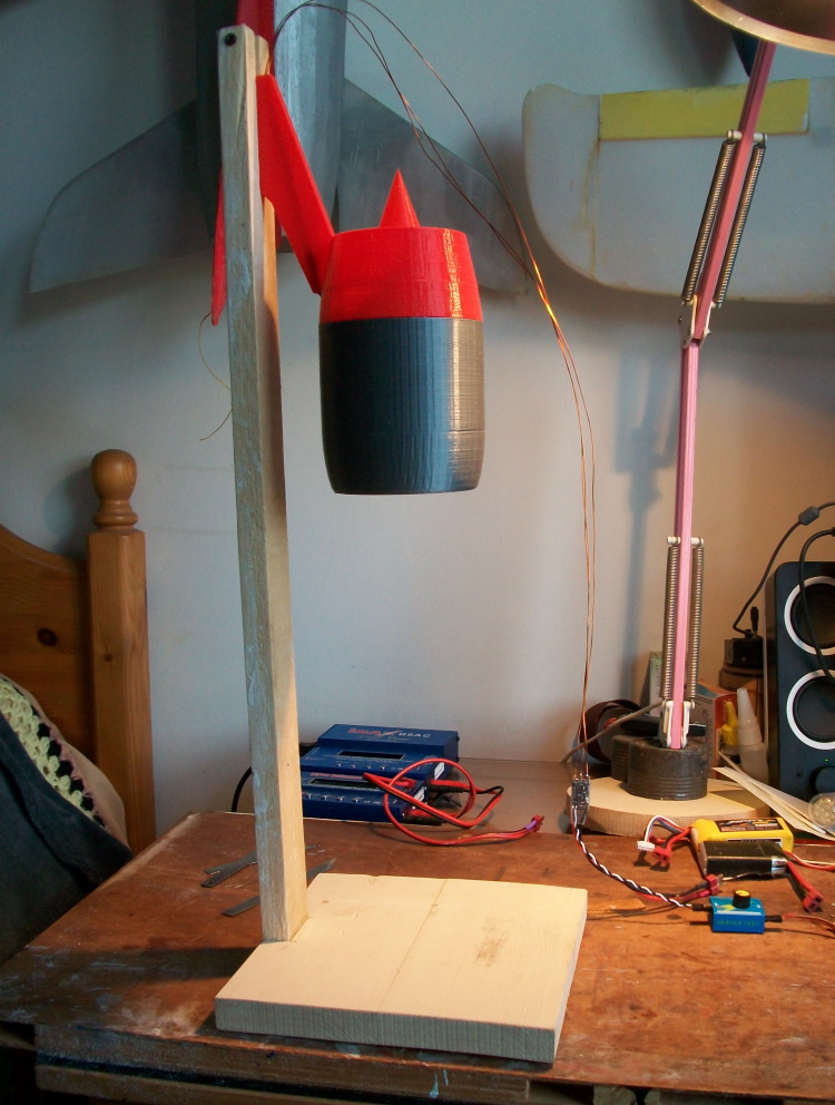
TestStand1.JPG

When run up on a set of kitchen scale it gives a direct thrust reading.
A whole series of tail cones were tried to give a range of exhaust areas from 100% to 80% of the FSA.
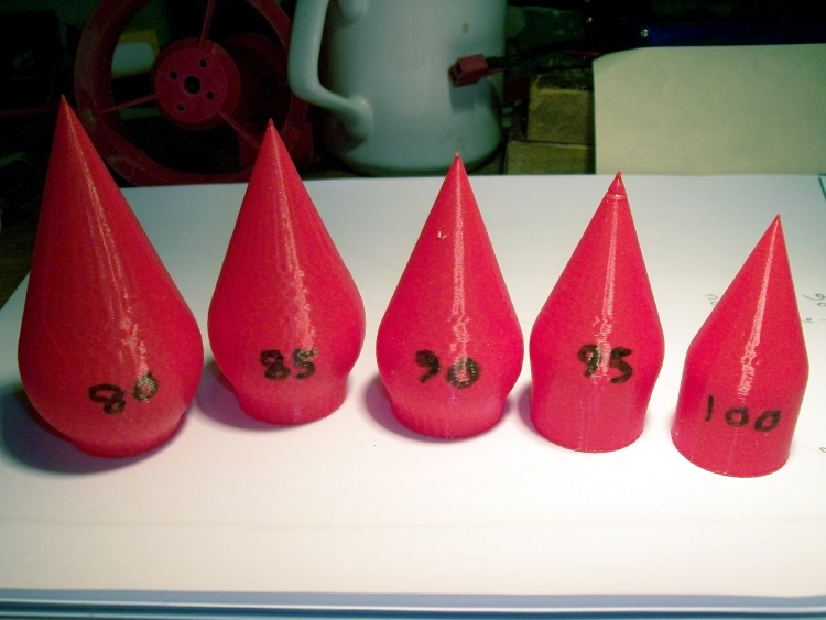
TailCones.JPG

There was a small increase in thrust (about 5%) to 230g with both the 85 and 90 FSA tail cones.
The slightly smaller 90% cone was finally chosen as it better mimicked that on the full size.
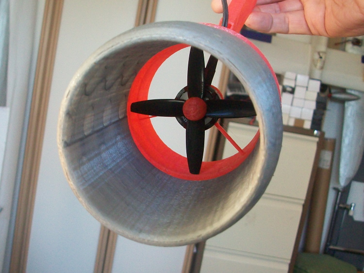
NacelleCmplt.jpg

Each nacelle requires nearly 7 hours printing time and of course there are 4 to do along with a filament colour change.
So a possible 1 kg of thrust. The finished plane was going to have to be seriously light.:eek:
To be continued.
 

quorneng

Master member
By far the most complex shape is of course the fuselage but I managed to find this 4 view on Google that includes a series of fuselage cross sections. Without them would have required some serious guess work and likely end up with it not looking 'right'.
an124_3v.jpg

The next task was to remove all the unnecessary surface detail to give a single line fuselage outline with the cross sections correctly positioned.
FuselageX2.jpg


Although the undercarriage is shown I strongly suspect the lack of thrust and weight considerations will mean it will have to be a "hand launch and belly land" design. In addition my rough grass field means it would probably have to flown like that even if it had wheels! ;)
It will require a number if intermediate formers but at least it will not be too hard to work out their profile.
To give an idea of size the fuselage will about 260 mm wide, 330 mm deep and 2360 mm long.

After many hours painstaking work on the computer you begin to see only problems and ask yourself why on earth why you are attempting such a thing. You also have a sneaking suspicion that you are doing it to prove you can rather than create a practical RC airplane.
 

quorneng

Master member
With the full set of intermediate formers the fuselage starts to look rather 'busy'.

FuselageFull.jpg

The formers will be printed so the first job is to design one!
FormerTest.jpg

Provided the side elements were sufficiently rigid the interior would have virtually a scale interior. That empty bit will be about 240 mm wide by180 mm high.
The test former printed using a light weight 'U' channel section. It weighs 5g.
FormerTestPrnt1.JPG

For construction the top and bottom sections of the formers would be printed as left and right halves so each half would be made up of 3 parts, top, bottom and side. With a total of 28 fuselage formers that means an awful lot of printing.
The fuselage will be built as a half shell over the plan. A technique I have used to construct of previous airline fuselages in Depron although not with printed formers..
It seems logical to start with the fuselage centre section as that includes where the wing will be mounted.
Some of the parts for the formers.
Centre1.JPG

No less than 28 parts will be required to make the formers for just half this 600 mm bit of the fuselage.:eek:
This could take some time!
 

mrjdstewart

Legendary member
wow! amazing work. saw one of these fly over head a few weeks ago. thought it was kinda weird, flight info said it was flying out of Hawaii non-stop to Tucson, then on. private cargo company.

good luck,

me :cool:
 

Timmy

Legendary member
With the full set of intermediate formers the fuselage starts to look rather 'busy'.

View attachment 181234
The formers will be printed so the first job is to design one!
View attachment 181236
Provided the side elements were sufficiently rigid the interior would have virtually a scale interior. That empty bit will be about 240 mm wide by180 mm high.
The test former printed using a light weight 'U' channel section. It weighs 5g.
View attachment 181241
For construction the top and bottom sections of the formers would be printed as left and right halves so each half would be made up of 3 parts, top, bottom and side. With a total of 28 fuselage formers that means an awful lot of printing.
The fuselage will be built as a half shell over the plan. A technique I have used to construct of previous airline fuselages in Depron although not with printed formers..
It seems logical to start with the fuselage centre section as that includes where the wing will be mounted.
Some of the parts for the formers.
View attachment 181253
No less than 28 parts will be required to make the formers for just half this 600 mm bit of the fuselage.:eek:
This could take some time!
do you use FreeCAD?
 

Tench745

Master member
After many hours painstaking work on the computer you begin to see only problems and ask yourself why on earth why you are attempting such a thing. You also have a sneaking suspicion that you are doing it to prove you can rather than create a practical RC airplane.
I relate to this oh-so strongly.
Also, if you're building each half over the plan, you might want some sort of support tying the upper and lower sections of your formers together until the aircraft is assembled to keep things from distorting. Just a thought, you have more experience with the half-plan method than I do.
 
Last edited:

quorneng

Master member
Tench745
You are quite correct. If you are using 'ring' formers you either have to use a 'keel' top and bottom and/or some form of 'jury' strut to keep things rigid until the two halves are joined.
One I did a bit back using Depron formers.
Ductplank1.JPG

Here both a keel and temporary cross struts are being used. In this case as it is for an EDF the formers are planked on the inside as well! The outer skin is only added after the internal duct is completely assembled. Tricky to do but the end result is very strong and stiff.
 

Mid7night

Jetman
Mentor
This is an AWESOME concept. I LOVE what you're doing with the 3D printed structure! It's perfect for something of this size and scale, and to get the open interior as you have.

Will you put a Depron floor and ceiling inside? I think it would add a lot of structural rigidity and strength for very little weight.
 

quorneng

Master member
Mid7night
It is an option but I have found that when fully skinned such a fuselage is remarkably rigid without any interior structure. Bear in mind a floor and ceiling would add 30%? to the area of Depron used and the Depron is as heavy as the formers. The weak point is really the side walls. A ceiling and floor would not help there.
Fortunately if extra internal Depron proves to be required the space inside is so large it will be fairly easy to add as I intend the whole nose door to be removable.
This construction is so unusual and with a requirement for extreme light weight some potential problems I just have to wait and see.;)
 

quorneng

Master member
The half shell off the plan.
Centre4.JPG

With the other half of the formers added and many hours of planking later this is what you have.
CentreSide.JPG

I had not realised just how obvious the undercarriage humps were.
CentreBumps.JPG

At least it means the fuselage sits level on the bench.;)
It is very 'empty' inside.
CentreFront.JPG

I am confident it will be plenty rigid enough for the aerodynamic loads but as for a hard landing! :eek:
I will just have to be gentle.
The fuselage section up to the nose door next.
 

Timmy

Legendary member
The half shell off the plan.
View attachment 181533
With the other half of the formers added and many hours of planking later this is what you have.
View attachment 181538
I had not realised just how obvious the undercarriage humps were.
View attachment 181539
At least it means the fuselage sits level on the bench.;)
It is very 'empty' inside.
View attachment 181540
I am confident it will be plenty rigid enough for the aerodynamic loads but as for a hard landing! :eek:
I will just have to be gentle.
The fuselage section up to the nose door next.
I'm exited to see how you do the nose!
 

FoamyDM

Building Fool-Flying Noob
Moderator
The half shell off the plan.
View attachment 181533
With the other half of the formers added and many hours of planking later this is what you have.
View attachment 181538
I had not realised just how obvious the undercarriage humps were.
View attachment 181539
At least it means the fuselage sits level on the bench.;)
It is very 'empty' inside.
View attachment 181540
I am confident it will be plenty rigid enough for the aerodynamic loads but as for a hard landing! :eek:
I will just have to be gentle.
The fuselage section up to the nose door next.
Great work so far. I am watching this for sure... Have you considered shear blocking. A couple bays worth of cross bracing in-line with the skin. or light rigid squares tight from rib to rib to provide torsional stability. 2 or 3 bays should provide enough for now. it is how buildings resist wind. Not the whole structure, but only a few bays,

In America, Depron 6mm and 3mm is being carried by www.RcDepron.com. Mr. Greg Tanous has picked up the ball. As a rough DTFB comparison it runs about $2 per sheet. (Depron sheets are nearly 2x as big.) Your Depron supply chain in USA has been restored.
 

FoamyDM

Building Fool-Flying Noob
Moderator
I'm sure you have considered this, but for the landing gear, to save weight but not have to hand launch, you can do a wheel cart for take-offs they could seat into the wheel well an like a nose wheel crutch with a bomb drop type release. and just do a belly land for the return..