
You are using an out of date browser. It may not display this or other websites correctly.
You should upgrade or use an alternative browser.
You should upgrade or use an alternative browser.
Rascal CNC
- Thread starter SP0NZ
- Start date
-
- Tags
- cnc diy foam board
Or remove the 4 bolts and replace the spindle mount with the needle cutter mount. The clamp seems pretty well built.
That was my first thought but then I saw the T-nuts those bolts mount into. I've had t-nuts like those work loose in the wood they're mounted to when they're tightened/loosened repeatedly. I suppose you could add a backer behind them to encapsulate them (and maybe a drop or two of epoxy if you're a "belt and suspenders" kind of guy) then just use slightly longer screws for the 8 that mount into the slots.
Of course...if the needle cutter and the spindle aren't the same length then you may have to loosen those 8 screws anyway to adjust where it sits. So I'll be curious to see how far the spindle extends past there when fully assembled to get a feel for how tall the cutter needs to be. Longer is better for the needle cutters since it makes for a gentler bend in the needle, but too long gets kind of silly
")
Duggem
Live like no one else...
I suppose you could add a backer behind them to encapsulate them (and maybe a drop or two of epoxy if you're a "belt and suspenders" kind of guy) then just use slightly longer screws for the 8 that mount into the slots.
They're sandwiched between the wood and aluminum channel, but I can see how they could work loose with repeated stress.
Of course...if the needle cutter and the spindle aren't the same length then you may have to loosen those 8 screws anyway to adjust where it sits.
I think this might be the best way. If you loosen the 8 tee nuts, which are metal on metal, so no worry about wear, then you can slide the spindle up and snug it down. This might give you enough room to then mount the needle cutting below.
Though now that I think about it, if we modified the wood at the bottom Z beam, it could allow for the entire spindle to slide right off the Z after loosening the 8 tee nuts. If you attach the needle cutter to a similar wood plate that the spindle is mounted too, then you could just slide it onto the Z and tighten it down.
I think this might be the best way. If you loosen the 8 tee nuts, which are metal on metal, so no worry about wear, then you can slide the spindle up and snug it down. This might give you enough room to then mount the needle cutting below.
Yeah, that's why I was leaning towards that - it seemed like a better place from a wear perspective.
Though now that I think about it, if we modified the wood at the bottom Z beam, it could allow for the entire spindle to slide right off the Z after loosening the 8 tee nuts. If you attach the needle cutter to a similar wood plate that the spindle is mounted too, then you could just slide it onto the Z and tighten it down.
Depending on the cutter design may not even need the wood plate. A 3d printed needle cutter could be designed to just mount right up. There's very little force on it so it wouldn't need all 8 mounting points, 2 or 4 would be plenty.
Or you could design a wooden needle cutter like David's mousetrap version - just leave the back plate wider and drill some holes so it can mount right to the Z rail.
But I haven't seen a fully assembled and operational machine yet so wasn't sure how easy this kind of swap may or may not be. Your mention of " if we modified the wood at the bottom Z beam, it could allow for the entire spindle to slide right off the Z" sound like what I was concerned about and if the design of the Z makes it easy to remove the spindle and it's plate or not.
Duggem
Live like no one else...
One thought I had was to reverse the bolts. Instead of T-nuts on the back, mill out a hex-shaped space for the heads. Use wingnuts to fasten the tool mount. Wood still might not stand up to repeated stress so maybe a nylon or aluminum plate for people who want to swap tools. I'm just trying to be lazy and not loosen / tighten 8 screws to change a tool
Last edited:
91shadowrider
New member
Are we for sure yet the parts listed are going to be the parts used in the build? I don’t want to order everything and then find out things have changed. Is there any new info on progress? Thanks guys.
blackkrystal73
Member
We are sure that these parts are the parts... of course as the project ages and upgrades are made by the community. The parts list might change reflecting the modifications etc. the parts list will build you the basic Rascal machine.
epsilon
Active member
Do you guys have any files for FT planes intended for the rascal yet? I ask because i'm board and trying to hold off on building until the first of the year so figured... why not play around with fusion 360. Be curious to see the final versions of stuff as well as not duplicate what others have already done...
blackkrystal73
Member
I have files for my larger machine, so does Todd, they will work on the Rascal. I would lean toward a different program for cutting out airplanes. Fusion 360 is some next level *hit...lol to complicated for standard 2D cuts. I recommend Sketchup or some other free software, i know Inkscape does cut paths and the MPCNC guys are using some freeware..
- Kevin
- Kevin
I have files for my larger machine, so does Todd, they will work on the Rascal. I would lean toward a different program for cutting out airplanes. Fusion 360 is some next level *hit...lol to complicated for standard 2D cuts. I recommend Sketchup or some other free software, i know Inkscape does cut paths and the MPCNC guys are using some freeware..
Some of the MPCNC guys also use sketchup with the sketch-u-cam plugin or inkscape with gcode tools. I'm not a big fan of either, sketchup in general just doesn't please me and the gcode tools for inkscape feel clunky and I have a hard time getting good code out of them.
There's also a free package called dxf2gcode but it's kind of annoying to get up and going and not very user friendly in my experience. The few times I played with it I also had issues with it generating so many tiny segments in curves that it would crash Marlin.
I actually use estlcam which isn't free but is very reasonably priced compared to other non-free CAM packages ($60 - and I see he's already selling it as a license for v11 even though only 10 is out so far so you're covered for the next major update.) I'm a cheapskate and love free software...but after trying estlcam I had no problem putting down the $60 for it because it's so much quicker and easier than other options I've tried. You can just keep using the demo version for free as well...but every time you export to gcode it pauses with a "please register" screen with the pause getting slightly longer each time you save. I made it 3 months before the pauses got long enough they started to actually bug me
I actually use estlcam which isn't free but is very reasonably priced compared to other non-free CAM packages ($60 - and I see he's already selling it as a license for v11 even though only 10 is out so far so you're covered for the next major update.) I'm a cheapskate and love free software...but after trying estlcam I had no problem putting down the $60 for it because it's so much quicker and easier than other options I've tried. You can just keep using the demo version for free as well...but every time you export to gcode it pauses with a "please register" screen with the pause getting slightly longer each time you save. I made it 3 months before the pauses got long enough they started to actually bug me
I am over a minute on that pause. It adds one second each time you save. I like Estlcam enough to deal with the delay till have the spare $60.00, which I will gladly pay.
Sketch-u-cam is a great option for me because I do my designs in Sketchup. But..... Since I also have the Export DXF plugin, I have been skipping Sketch-u-cam. I prep the file to an Estlcam friendly setup and export as a DXF. Open the DXF in Estcam and produce the Gcode.
For a regular PDF set of plans, that is when inkscape comes into play. Open the PDF in inkscape and make whatever adjustments you want and save as a DXF. Then open that in Estlcam.
Regardless of the process you use there are two things to note here.
1) unless the two machines are identical, it will be hard to share gcode. - A DXF file seems to be the least common denominator that could be shared successfully. Given the amount of labor saved from tiling, transferring and cutting by hand, the conversion from DXF to your specific flavor of Gcode is a small price to pay.
2) do not hold your breath for FT to release DXF files. - I am not saying it won't happen. But I have not heard of any plans for them to release DXF's. Personally, I think they keep them close hold for proprietary reasons. I could be wrong. That's just the feeling I get.
epsilon
Active member
Thanks guys. I guess I was leaning towards fusion because 1. I already had some experience with sketchup and 2. I eventually want to get into designing things for 3d printing so figured more practice the merrier but it sounds like for this particular application that's not the best route to take.
Thanks guys. I guess I was leaning towards fusion because 1. I already had some experience with sketchup and 2. I eventually want to get into designing things for 3d printing so figured more practice the merrier but it sounds like for this particular application that's not the best route to take.
There's no reason you can't use Fusion. It's just kind of overkill for the job at hand
I've tried using Fusion for CAM once or twice since there is a post processor for it to generate gcode for my MPCNC. But it was a lot more work than doing the same thing in estlcam. If I was doing some kind of fancy setup with multiple tools, and fixtures/setups - then Fusion would be way easier to use than estlcam - but I'm not doing that kind of stuff.
I've also tried a CAM plugin for onshape and found it similar to the CAM in Fusion. Really nice for more complex stuff, but not a workflow I'd want to use for cutting foam sheets.

Allenhat
Member
The cut instructions have been added to the zip plans on the first post.
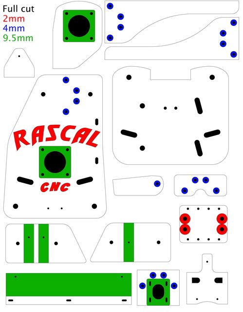
Are the parts at the top right corner supposed mirrored images of each other? they appear to simply be the same part rotated.
Are the parts at the top right corner supposed mirrored images of each other? they appear to simply be the same part rotated.
Yes, you need 4 total. Two of each as shown.
Similar threads
- Replies
- 6
- Views
- 1K
- Replies
- 54
- Views
- 14K
- Replies
- 3
- Views
- 1K
- Replies
- 4
- Views
- 3K