So I bought a cheap 40w laser....

jhitesma

Some guy in the desert
Mentor
I've been toying with getting a co2 laser for awhile, I love the little 3w laser I have on my MPCNC...but cutting even 1/8" ply with it is beyond tedious the number of passes it takes. I've tried both lens options and air assist but it's still just too slow for my preference and results in way too much burn on the edges. It's great for engraving and cutting paper and craft foam but not great on wood. Plus it's an open machine and I only have one pair of good laser safety glasses so I have to keep my shop locked while using it. Not idea.

But the "K40" machines are pretty limited and have been too expensive for me to justify. Then I saw @nebraskatrevor's post: https://forum.flitetest.com/index.php?threads/home-built-co2-laser-for-dtfb-lots-of-pics.55554/ with what he did to his and got curious enough to do some more research.

My research pretty much said the community around these machines is no longer recommending buying a k40 - they're saying the new 50w machines are much better. And it appears they are. They have nicer controllers, more power, larger cutting area, come with air assist....but they're also a lot more expensive (~$1,500) and shipping is an issue because they're BIG machines. So you're looking at freight shipping and an extra $150 to get liftgate service for residential delivery. Ugh.

K40's meanwhile have come back down in price and are easy to find in the $350 price range. And when I came across a one day 15% off anything on ebay coupon that brought a K40 down to $300 and I couldn't say no (incidentally that's the same price point that made me finally buy a 3d printer a few years ago...history repeats?)

So - I placed the order and it arrived yesterday.

20181003_180557.jpg


It's smaller than the 50w machines...but still...quite large! Part of the reason I decided to dig in on this is I wanted a "desktop" project I could work on in my dining room. Due to a recent life change I'm not able to spend much time out in my shop anymore and am looking for projects I can do in the house - preferably with my daughter. She's expressed interest in lasers and this seemed small enough to work on inside...so....

20181003_181213.jpg


The packaging was not very impressive but worked. Honestly I'm amazed this thing could make it here from China packed like this, but it did! Well...mostly...more on that in a moment.

20181003_181650.jpg


Inside the machine were more goodies. The box for the water pump actually had more stuff packed into it as well.
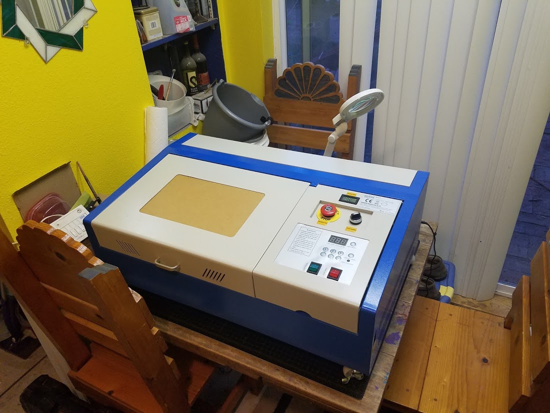
20181003_182709.jpg


I had measured my table before ordering...but still it's bigger than I expected. Those wheels on the bottom are listed by the seller as an "upgrade" but honestly for me they're a liability and make it even taller. I'll be replacing them with some feet...assuming I keep the factory case.

The control panel is also listed as an "upgrade" but...I'd rather have the simple knob and analog gauge than this travesty:

20181003_182746.jpg


And as I said there is some minor shipping damage:
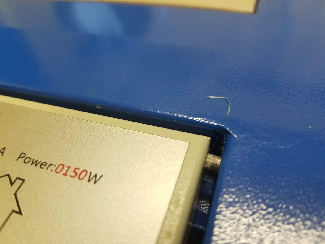
20181003_182732.jpg


That's the worst of the shipping damage but there is some on the laser side as well:
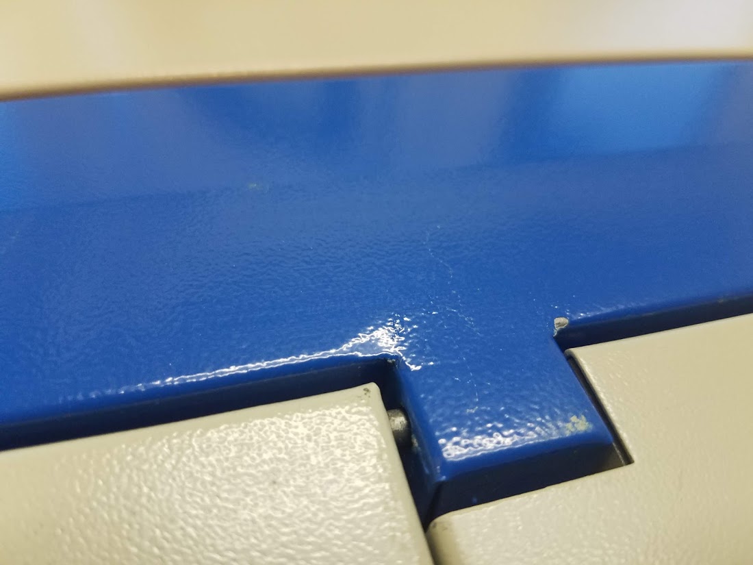
20181003_182728.jpg


I'm not going to make a stink about that though - it's just cosmetic.

So it's here! And so are a few upgrades I ordered for it since my research indicated that the stock mirrors and lens are pretty worthless:
20181003_182444.jpg


Hopefully I bought the right size....we'll see. I also ordered an air assist nozzle...I could 3d print one but it was only $20 for an aluminum one....then I found out the machine came with one:

20181003_190212.jpg


But more on that later. I want to do a thorough review of what came with the machine, what "upgrades" this one included and my opinion on all of it. Then I'll get into my plans to upgrade it properly ;)

That will have to wait for later though, gotta focus on some actual work right now :D
 

Attachments

  • 20181003_182746.jpg
    20181003_182746.jpg
    135.3 KB · Views: 0

rockyboy

Skill Collector
Mentor
Very interested to follow along with this! :D

My daughter has had a couple opportunities to work with laser cutters in school and camps and one of these might finally give us another "daddy - daughter" hobby connection! (She did one FT plane with me years ago and one buddy box session, but hasn't really been interested since... :cry: )
 

jhitesma

Some guy in the desert
Mentor
So, before we get into my thoughts about this machine...let's take a quick peek at what the e-bay seller says is "upgraded" over other similar machines:

lc_diff.JPG


Ok, is any of this actually worth it? Well.....

1) This was the one I was most interested in that seemed like the biggest benefit, co2 tubes need to be water cooled so monitoring the water temp is pretty important to a long life from the tube. Not including a temp display seems like a gross oversight. But...the one this machine comes with is pretty lame. It's battery powered, the sensor is just stuck to the outside of the water hose with some electrical tape:
20181004_131000.jpg

and the readability of the display is terrible. If you're directly above it it looks great. If you're even a little bit off to a side...it's unreadable. I'm going to have to tap @nebraskatrevor to find out where he got the snazzy one he used to replace this.

2 + 3 ) Master power and e-stop switches. I can't believe the others don't come with these! I mean you can get them for a few bucks and wire them in yourself...but still - they should be there. Of course there are a number of other things that should be there that aren't on this machine still (stay tuned.)

4) Digital control panel....no thanks. I'd much rather have the old analog. This is clunky and hard to use, the display is hard to read in normal room light. It's all one PCB bolted to the case so there's no keeping part of it - all or nothing here:
20181003_192525.jpg


5 + 7) LED and switch. Seriously, counting a switch for the LED...they just had to sneak in one more item! The LED is nice. It's a bit bluish, but behind the orange safety window it looks good. But...I have tons of LED strips so could add my own no big deal if there wasn't one.

6) Window supporter. I guess it's nice. I mean the lid holds itself open fairly well since it opens past 90...in fact it holds itself open before this even engages. So kind of point less. And the installation...not exactly screaming "high quality":
20181003_185616.jpg


8) Extra power socket. I guess it's nice...you can plug in a water pump and an air assist pump. But, it's nicer to have the air assist on a switch so you don't have to have it on ALL the time. And both of these are just wired right off the main power switch - so any load on them also goes through the switches. I note compared to the older models they show that they gave up a fan to add this though - I'd rather have the extra fan. There's no fan in the electronics compartment other than the one built into the power supply. The extra sockets seem like an afterthought:

20181003_192635.jpg


Note - the ground wire to the case looks like it's probably just a joke - I haven't confirmed but it appears that the paint on the case wasn't removed under it so it's not actually grounding the case. The small zap I got touching the case at one point would seem to confirm this. It's apparently a common issue with these machines and an easy fix.


9) Wheels. For me these are a liability, my table is too small. The front wheels lock which helps but I still plan on removing them and using some shorter feet instead as the machine isn't going to need to roll anywhere.


So...yeah, I'm not that impressed with the "upgrades" but they don't really charge extra for them so no biggie and most of them don't actually make things worse. If i had to buy it again though I'd look for one with the analog meter and knob just because it's less annoying until you swap out the electronics.

On the upside the wiring is surprisingly well done for China:

20181003_192519.jpg


Everything is terminated well and heat shrink is used where appropriate. It's all in split loom and well routed. But...if you look closely you'll notice that basically every mounting pad holding it in place is coming loose. At least that split loom will be relatively easy to remove to gut this thing.

The board in it is the standard "m2 nano" board that most of these machines come with.
20181003_192621.jpg


I'm NOT big on how they used a ribbon cable for the endstops and X stepper - those things aren't really designed for the kind of current steppers like. Pretty sketchy IMHO and these boards are junk anyway. They talk some proprietary protocol and the stock software is a real pain to work with. I'm not even going to risk putting the CD in my drive (if I even had one) or the USB stick into any of my computers.

There is 3rd party software K40 Whisperer which people rave about...and to me that only proves how terrible the official software is because I was not at all impressed by K40 whisperer.

And honestly upgrading this thing is pretty simple (other than that ribbon cable) so I'm not sure why anyone would stick with the stock board. But controller upgrades are going to be a later post...

Despite those "upgrades" the machine is still lacking any kind of safety interlocks. Which is just nuts. I'm shocked that they can get away with even selling these. At least the seller I bought from doesn't try to claim FDA compliance like some do....but it's still not supposed to be legal to sell a laser device that doesn't meed FDA requirements and there's NO WAY that this thing does. Of course one that does would be much more expensive...but it won't be that hard to add some safety features to bring this one close enough to compliance for me. Right now I don't even like having it plugged in while my daughter is in the house because it's so far from safe.


The machine did come with another "upgrade" that wasn't mentioned...an air assist nozzle:
20181003_190212.jpg


At least I assume that's what it is. Looks like one. It was packed inside the water pump box (along with the stock outlet for the pump and a brass one that adapts it to the hoses on the machine.) But that sure looks like an air assist nozzle to me.

Except, I have no clue how you could use it. It doesn't fit on the lens assembly in any way I can figure out....and I'm pretty good at figuring out how things go together ;)

The Laser tube also looks nicer than what I've seen on some of these machines. A lot of people say theirs has no label or specs...this one at least does:
20181003_192915.jpg


Closeup:
20181003_192944.jpg


Assuming it's correct then it IS 40w as advertised, was just made a few months ago, and there's even some manufacturer info.

Appears to be the "pu700" listed on this page: http://lasertube.cn/en_lasertube1.htm

Which indicates that while it's listed as a 40w tube it's actually 32-40w so probably not likely to actually be 40w. \

Speaking of the tube...this is a good time to mention one of my other gripes about the machine. Do the Chinese not know about grommets? Seriously - there are so many wires running through unfinished holes it's shocking:

20181003_192923.jpg


That the 10kv high voltage lead to the laser tube....just running through an unfinished hole. Yeah, it shouldn't be moving around much (or at all) but still...that's just neglectful. The water hoses do the same thing, as to the temp probe and ground wire for the tube. I can't get my finger in any of them to feel how rough they are but the water lines show possible signs of damage already so this is going to have to be dealt with.

What also stands out to me is how much wasted space there is in this thing. The working area is barely 8"x12" (and the work clamp is a joke BTW.) but the machine is 32" wide 20" deep and 12" tall (which I'm pretty sure doesn't include the height of the wheels.) You can see from the photo of the laser tube that there's not much they can do to make it any narrower. But look at how much space is wasted inside this thing:

20181003_193530.jpg


I wasn't planning on making it larger right away...but man this is tempting. Even if it's more so I can make it more compact than to increase the cutting area. But that would require shop work which I can't really do right now. So for now I'll have to live with this beast on my dining room table. Good thing my daughter doesn't like to eat there!

Tonight I'll start discussing control board replacement options!
 
Here is the temp sensor I use. It has a stainless probe that is 4mm in diameter so I just made a "t" in my water line that has a 4mm push connect air line fitting that the probe slides right into. The tip of the probe is right down the water stream, as it leaves the laser tube. There are lots of opinions as far as temp goes. Some want their tube super cool, as for me I just keep it below 75 deg F and it seems to do no harm to the tube.

https://www.amazon.com/dp/B01DVSIYN2/?tag=lstir-20
 

jhitesma

Some guy in the desert
Mentor
Alright, let's discuss controller options. The M2 nano that it comes with is as already discussed pretty hopeless. Honestly I'm kind of surprised that no one has just come up with better firmware for them, I can't find any real details about it so maybe it's just a matter of not enough details about the board to bother when other options are available. Or maybe the MFG locks the chips so they can't be reflashed. I can't be bothered to research deeper and find out because there are plenty of other options available.

There are 3 main firmware options: GRBL, Marlin, and Smoothieware. Yeah, there are others (repetier firmware, reprap firmware, custom forks of the 3 biggies, and some other more specialized options) but those 3 are the most popular.

GRBL - this is the granddaddy of them and has been around a long time. It's also the most basic but is very popular for CNC machines. It can't do 3D printing like Marlin and Smoothie, but it's gcode is the most "standard" and it works the most like a traditional CNC machine. It can't support a local LCD interface or sdcard to run untethered - but it's easy to configure since almost all of the settings you'd need to change can be changed with gcode commands. Usually used with cheap <$20 arduino uno based CNC shields but can also run on arduino mega/RAMPS though I've had mixed results with that port.

Marlin - Primarily a 3D printing firmware it's been getting more and more updates making it nicer to use for CNC work. You can attach an LCD and SD card to run stand alone which is very nice. It will run on a VERY wide variety of controllers and supports all kinds of stuff most of which is crazy overkill for a laser cutter. One big downside to Marlin is it's queue - it doesn't execute gcode one line at a time but instead queues up chunks of it. This is nice for 3D printing...but for CNC work means you can't follow the exact position of the machine while it's operating and can't stop the machine as accurately. If you just fire up a job and go it's fine, but if you want to do more advanced stuff and need to micromanage the job then that queue can get in your way. Configuring Marlin can be a pain since many settings have to be changed before the firmware is compiled or flashed. A lot of them can be overridden in eeprom - but it's not very reliable and generally best to set them before compiling.

Smoothie - I have no experience with smoothie yet. Mostly because the hardware options are more expensive and therefore less popular which prevents them from being more widely produced and getting cheaper...but it's been gaining popularity and prices are getting better on hardware as is availability. Smoothie is a more modern approach which is easier to configure and upgrade. This is in large part due to the more modern hardware with faster more powerful 32bit processors. I've been wanting to try smoothie and it has a lot going for it - I'm not sure how well suited it is for CNC and whether or not it has Marlin's limitations there as well....I need to do more research on that.

Those are the 3 main firmwares I'm considering. But...what about hardware? Well, I have 3 options on hand that I could use tonight if I wanted to:

Classic CNC shield:
20181004_212105.jpg


These things are widely available on amazon/ebay/banggood/aliexpress for <$20. They usually include A4988 drivers though i've swapped in a DRV8825 (I much prefer the DRV's...they tend to run cooler, they can do finer microstepping, and they run the motors MUCH quieter.) I haven't run this on an actual machine - just hooked up some steppers and played around. I picked it up since I was really liking cncjs on my MPCNC and wanted to try a GRBL board since the Marlin queue was getting annoying to deal with. Though - messing with it reminded me of all the things in GRBL that I wasn't a huge fan of. But...it may be the quickest/cheapest/easiest option for getting the laser up and running. If it wasn't for the ribbon cable I could have this thing wired in in just a few minutes.

Next up is RAMPS:
20181004_212111.jpg


Probably the most popular control board. Can run GRBL or Marlin (along with a bunch of other variants of both) and has tons of I/O for lots of options. This one is currently wired up to my eggbot I've taken it off for side-projects before but I'm not in a big rush to tear it apart again. I have a spare non-graphical LCD I could put on it...but don't have a spare graphical one (and those are much nicer) so I'd mostly still need to run it tethered defeating one of the main benefits it brings to the table. If I wasn't interested in trying smoothie I'd probably just go ahead and toss this in.

My third on hand option is an Ultimachine Archim:
20181004_212303.jpg


Which...isn't really much of an option. Ultimachine kind of moved on to a new Archim2 with much nicer stepper drivers before firmware to support this version really materialized. There's a port of Marlin that runs on it...but it's outdated and not being updated. Marlin 2.0 might be able to work with it - but I haven't tested yet. Last time I tried there were issues with the stepper driver current settings though last time I checked it appeared those issues may have been fixed. It's a nice board...but...not a great option for this project due to the lack of good firmware options.


So right now it's looking like I may toss the GRBL board in there as a temporary solution. I may also toss on a Raspberry Pi or something similar so I can use it "untethered" (Technically it would still be tethered - just it would be tethered to a dedicated computer and I'd be able to interact with it over a web interface) with cncjs or laserweb (or even lightburn if I decide to spend the money for it....which I probably will.)

But...I think I'm going to order a smoothie board to use since I've been wanting an excuse to try smoothie. There are 3 main hardware options going that route:

1) Official Smoothie. They offer 3X/4X/5X variants which refer to the number of stepper drivers they have, the 3x is <$100 and would be sufficient for a laser engraver...but the 4x and 5x have built in ethernet which is nice. It uses A5984 stepper drivers and controls the current settings on them through software which is nice. Availability is still not what it could be though....only one of the US distributors shows them in stock and they don't have all of them available.

2) MKS Sbase. This is a chinese clone of the Smoothie. The smoothie team hates it. It was cloned in violation of their license, the original boards had serious issues, and in general the smoothie team won't provide help or support to people using them. Instead of the A5984 drivers they use DRV8825's....usually...there are variations with different drivers. They do still set the current through software. They're only $70 but...risky due to the lack of support from MKS and unwillingness of smoothie to support them. If you run into any issues you're pretty much on your own. The price is tempting...but I don't think I'll be going down this particular rabbit hole.

3) Cohesion 3D. Like @nebraskatrevor used. This is basically a smoothie board repackaged to be a drop in replacement on these machines. That's nice for a machine like mine since it solves the issue of dealing with the annoying ribbon cable...except I want to eliminate that cable anyway so not a huge benefit for me. My biggest issue with the cohesion boards is their use of external stepper drivers and the A4988's that I'm not a fan of. You're back to manually setting current with that setup which I really want to get away from. A great option if you're looking for a turnkey solution that's proven and easy...but...not really what I want.

So....I'm probably going to be ordering an official smoothie, but I may pop the GRBL shield in there while I wait on it.

And that brings up the software side....cncjs, laserweb, lightburn.....oh boy! But...that will have to wait for a followup ;)
 
I can not possibly overstate that whichever route you go lightburn should be at the top of your list! I am cheap and it is possibly the best 40 bucks I have spent in the last year or two period.
 

jhitesma

Some guy in the desert
Mentor
Here is the temp sensor I use. It has a stainless probe that is 4mm in diameter so I just made a "t" in my water line that has a 4mm push connect air line fitting that the probe slides right into. The tip of the probe is right down the water stream, as it leaves the laser tube. There are lots of opinions as far as temp goes. Some want their tube super cool, as for me I just keep it below 75 deg F and it seems to do no harm to the tube.

https://www.amazon.com/dp/B01DVSIYN2/?tag=lstir-20

Thanks - that will be much nicer than the stock one! I'm not sure how big of a deal temperature is. But...I live in the desert. Right now when I come home my house is at 85-90f and my tap water is about the same - and we're past the hottest part of the year now. So....cooling is going to be a bit of an issue. Ice in the water doesn't seem like a great long term solution. So I'm going to have to eventually look into some kind of cooling assistance. I don't want to pay for a full on commercial cooler. When I get home in the evening water sitting out is reading 32c - so I do need to do something to cool it down even before I start firing the laser.

I'm debating something as simple as running the water hose through a copper coil in a cooler as a heat exchanger...or looking into radiators for water cooled PC's....or a peltier solution....or using a cheap air conditioner (think I even have a spare one laying around) and hacking into it....

For now...I'm just dumping ice into my distilled water...but that contaminates the water and is far from ideal. Given that the laser tube is probably 80% of the price of the machine I do want to treat it well!
 
Regarding Marlin and it's queue, isn't it possible to reduce the queue size to 1 ? (Which could be problematic or not work at all...)
 

jhitesma

Some guy in the desert
Mentor
Regarding Marlin and it's queue, isn't it possible to reduce the queue size to 1 ? (Which could be problematic or not work at all...)

I believe there are issues with doing that. Like it affects the path planner and you loose a lot of efficiency in how it moves. I'm also not sure shrinking it's size is all that trivial...it's a pretty core part of Marlin.

And honestly it's not THAT big of a deal. I've lived with my CNC and Marlin for 2 years without too many complaints. But...I usually just load up my code on a SD and hit go. I've been starting to get into things where I want work coordinates separate from machine coordinates to setup complex jobs and want to be able to pause and resume if things go off....and that's where Marlin starts to be limiting. There have been recent changes to add work coordinates to it but I haven't upgraded to test them yet. And you can pause a cut...it's just it will still do a few more moves after you tell it to pause before it actually does - which isn't ideal in a panic situation :D
 

jhitesma

Some guy in the desert
Mentor
Oh - and I went ahead and ordered an official Smoothie x4 over lunch. The x3 would be plenty but I want the ethernet and don't want to have to hack it into the x3 myself. Plus this way if I decide to use the smoothie in my printer instead it will have enough drivers.
 

jhitesma

Some guy in the desert
Mentor
Didn't have time to work on this over the weekend. Took my daughter to Maker Faire in San Diego - which didn't go as well as I'd hoped. She didn't like the crowds and was being difficult as a result. I managed to see @sprzout - but we didn't even get to say hi because he was so busy helping kids build FT STEM gliders (and my daughter didn't want to wait in line for a turn.)

But...I'm probably going to go ahead and swap in the GRBL board for now since I don't know how long it will take to get my smoothie. Got the order acknowledgement on Friday - but no shipping notice yet. So we'll see how quickly they ship it.

I also ordered an ammeter since the digital display doesn't include one and I want to know how much power is going through this thing.

Going to the laser tube manufacturers site and looking up my tube I see that it's listed as 16-18kv ignition voltage at 4-5ma and 10-11kv working voltage at 13-16ma. The digital interface apparenty shows "percentage" but percent of what isn't clear. I'm guessing it's percent of the 0-5v control signal it sends to the power supply.

Actually...I should probably back up a bit here and explain how these things work....

If you look at the photos of the right side of the machine opened up you'll see a large blue box. That's the power supply. It provides 3 types of power:

1) 5v DC to power the control board.
2) 24v DC to power the steppers.
3) HV for the laser tube.

The 5v and 24v are probably fairly familiar to anyone with a bit of experience in RC. Nothing special there.

But the HV side...well that's where things get interesting - and scary. Laser tubes run off of very high voltages - 16-18kv (that's 16,000-18,000 volts!) but they do so at low current (4-5ma to start and 13-16 when running). So you use a ma (miliamp) meter to see what kind of power is going to them. Now I'm going to have to assume that 13-16ma is the max current when running - since that wouldn't give much room for power control. This site here has a nice power% to ma table (assuming 20ma max) and would back up my assumption: http://lensdigital.com/home/?p=1453

Bottom line - the laser runs at a fixed voltage but you vary the amount of current the power supply will allow to control it's strength. The power supply takes in a 0-5v signal to tell it how much power to output - 0v is no power 5v is 100%. On the older K40's this is controlled with a potentiometer (i.e. knob) and you're simply varying the voltage to that pin on the power supply by turning the knob.

With a nicer controller you let the controller set that voltage - it does with with PWM (Pulse Width Modulation) meaning it turns the power on and off really really fast to give the effect of lower power. (digital circuits are either on or off, they can't be partly on. So to get 3v from a digital circuit you have to take a 5v signal and turn it off for part of the time so it averages 3v....it's a bit trickier than that but PWM is an article in and of itself so we'll leave it with that for now.)

With GRBL and a CNC shield you can only do 8bit PWM due to limitations of the processor. This will give you on and off control as well as some power control...but not very fine power control. RAMPS will give you finer control since it has a more powerful processor and better PWM outputs...but smoothie will give you the best since it has the fastest processor and nicest PWM outputs.

No matter how you control that 0-5v input to the power supply you really should monitor the current on the laser to know how much power you're giving it. So...as I mentioned I ordered a 0-30ma meter and will be installing it. Until I get it I'm really not in a huge rush to fire up the laser since it's hard to tell just how much power I'm giving it with the digital panel.
 
For what it is worth I never let my tube be driven with more than 10Ma of current. You can apparently go up to 15ma for short periods of time but the interwebs tell me you should never exceed that threshold. I physically set the potentiometer on mine to allow only 10ma at max and then I let the software/Cohesion3D/Lightburn control it from there using the aforementioned PWM control. I am much more concerned with longevity than I am with the increased power. In reality these tubes are good for around 32w at max not the 40 claimed by China. You can buy a tube that actually outputs 40W but it is 6 or 8 inches longer than the stock tube. When and If my tube goes bad I will surely replace it with one of those as they only cost a few dollars more. I dont have a safe way to measure the voltage supplied to my tube so I am unsure how many W my 10ma translates to.
 

jhitesma

Some guy in the desert
Mentor
For what it is worth I never let my tube be driven with more than 10Ma of current. You can apparently go up to 15ma for short periods of time but the interwebs tell me you should never exceed that threshold. I physically set the potentiometer on mine to allow only 10ma at max and then I let the software/Cohesion3D/Lightburn control it from there using the aforementioned PWM control. I am much more concerned with longevity than I am with the increased power. In reality these tubes are good for around 32w at max not the 40 claimed by China. You can buy a tube that actually outputs 40W but it is 6 or 8 inches longer than the stock tube. When and If my tube goes bad I will surely replace it with one of those as they only cost a few dollars more. I dont have a safe way to measure the voltage supplied to my tube so I am unsure how many W my 10ma translates to.

Yep, in fact the 50w machines usually actually come with "real" 40w tubes. Basically you have to take 10 off of the quoted power in the ads to get a ballpark figure of what the tube is actually going to be rated for ;) Measuring the voltage is tricky at these power levels.

10ma should be very safe. You're probably only at about "35%" there which should be fine.

The figures quoted here: http://lensdigital.com/home/?p=1453 seem about right:

10% = 4ma -> 80% = 20ma

I did some low power tests on my machine starting at "6" on the digital panel which got me nothing. But once I hit 9% on the panel it was able to create a beam. So if 9-10% is about 4ma then that would make sense. At 9% the tube sounds "crackly" though so I suspect it's just barely enough current for it to lase. Even so it's enough to punch a hole in cardboard if I hit the test button for less than a second.

I went as high as "21" on the panel which was probably around 8ma and at that point it was able to blast a hole through DTFB with a quick tap of the test button and was able to put a nice pit into some 1/8" ply but wasn't able to get through it. This is all just test firing the laser though with no movement and no air assist yet. Taking it easy until I have a power meter in there ;)


This digital panel BTW. Ugh is it terrible. Apparently if it's showing numbers that indicates that it's "armed" and ready to fire. If you press the "Laser Switch" button then the display goes blank except for the decimal point - which apparently is how it indicates that it's "safed". But if you power the machine off with it safed then when you turn it on again it will revert back to armed. Really sketchy.

I plan on adding a latching switch instead (along with a few microswitches on the panels) so I'll have a mechanical way of telling if it's armed or not. In fact...just decided...instead of a latching push button which I was initially thinking this seems like a perfect place to use a "missile cover" toggle switch:

517eee88ce395f521d000000.jpg


Yeah...that seems about right for the master laser enable/disable :D Pretty sure I still have one sitting around somewhere...think it even has a LED in the tip to indicate when it's on. Will have to check my parts bins tonight.
 

jhitesma

Some guy in the desert
Mentor
I may not want to fire up the laser until I get my ammeter...but...that doesn't mean I can't start working on the motion platform ;)

I went ahead and ordered a "K40 middleman" board and the ribbon connector to go with it. ($0.50 connector, but $3 S&H. Even ordering 3 of them to go with the minimum order of PCB's I paid more for shipping than I did for the connectors - hate when that happens!) I do want to replace the ribbon completely...but I may wait until I expand the mechanics to do that. So for now this will let me get moving quicker...except...it will be a few days until I get the connectors and even longer for OSHPark to get me the boards (BTW I'll have 2 spare boards so if anyone else is doing this and wants one drop me a message.)

Then at lunch I had a bit too much coffee and decided to just dig in a bit:

20181008_134914.jpg


There's the original "brains". Not much to it. The two squarish chips at the bottom are the X and Y stepper drivers. Standard super cheap allegro A4988. (Though interestingly enough the same that cohesion ships with their smoothie based board. So any difference in stepper performance/noise is more due to how the stepper drivers themselves are driven and/or configured. )

The big rectangular chip in the upper left is a CH341a which is a cheap Chinese clone of the more reliable and higher quality FTDI USB driver which is extremely expensive (this whole board is probably made for less than a genuine FTDI driver sells for.) The big square chip next to that would be the main brains of this thing....and probably explains why there's no alternative firmware. I can't find any references to it by any of the numbers stamped on it. So no clue just what it is. I could try looking at what the pins appear to be doing and try to figure out what kind of microprocessors match...but..why bother. It may even be a custom chip just for this kind of thing. Swapping out the whole board makes more sense than messing with this mess though.

20181008_134931.jpg

Much better. More room already ;) This kind of shows how simple the wiring is. The white 4 pin connector is the only connection between the control board and the laser itself. And 3 of those wires are for power. The brown is 24v, Green is Ground, and Yellow is 5v. The Grey wire is "Laser Fire" and is used to tell the power supply to turn on power to the laser. There is of course no connection to tell the power supply how much power to use - that's all controlled by the digital input board (or on older K40's the potentiometer.)

The "two" wires off to the left are the controls to the motion platform. Inside the black wire wrap are the 4 wires for the Y stepper, and the ribbon cable carries the X stepper wires and both X and Y endstop signals.

I should get the vacuum in here and clean out that packing styrofoam before I go much further.

20181008_135705.jpg


Begone foul beast. This is the "brains' that control the laser itself. One chip who's markings have been shaved off. But basically all it does is display a value on the LED's, toggle the laser "safety" line on or off, and send a PWM signal to the laser power pin. Glad to be rid of this thing even more than I'm glad to be rid of the main "Brain".

20181008_135709.jpg


Yeah, that's actually looking better to me. Eventually I'll make a custom panel. But for now I'll just hack this one up as I add/remove things and figure out what I want.

One other scary thing in here...the way the power supply is wired:
20181008_135133 (1).jpg


Let's go over what these connections are - then why it's so scary.

The 4 wires on the left are "High Power". The Black wire on the left is the ground from the laser tube itself where the HV returns to the power supply. That's the wire we'll be tapping into to add my ammeter. The Yellow wire is the main chassis ground - it runs to the power cord, auxiliary outlets, and the ground lug (but not the actual chassis it should also run to.) The red and blue wires are neutral and live from the wall. So basically you've got one side of the laser tube connection and the three wires that come in from your wall.

The next two connectors are where things get interesting. From left to right the signals are:
G/P/L/G/In 0-5v/5V And 24V/G/5V/L

What are those?

Well, the G's are all Ground there are just multiples there to make wiring simpler.

The 2 L lines are for firing the laser. They're tied together internally and either can be used to turn the laser on when it's armed. The one on the left connector is usually wired to the laser switch on the control panel while the one on the far right of the right connector is the one that goes to the brain board so it can tell the laser to fire (that grey wire in the 2nd photo above.)

The 24v and 5v lines on the left side are just power output for the control board.

The P line is the safey interlock. It has to be tied to Ground or the laser won't fire. On the older models it's and the G to it's left are connected to the "Laser Switch" (the L line and G are then tied to the "Test Switch"). Note how on mine the P and G are just tied together...

The last three connections on this middle connector are how the laser power is controlled. G/In/5V. Basically one side of a potentiometer is wired to Ground, the other to 5v and the middle (i.e. the point between 0 and 5v that the knob is turned to) is connected to the In. For connecting to a different brain board we don't really need the 5v or G here we'll just send our own 0-5v signal generated using PWM on the controller.

So...what's so scary about mine?

Well...remember in my last post how I complained about the way the digital board always resets to "armed". And the way that the safety pins are just shorted together? Yep, the only "safety" on this thing is entirely software controlled. If that cheap junky digital control board freaks out it will just fire that laser. There's no secondary safety like the older models had with the Laser Switch as an actual switch!

Those pins are also going to be important since that's where we'll wire in our real safety switches. The "missile switch" and door switches will all be wired in series across that so if any one of them opens the laser will be disarmed. I may also wire it through the control board so software can issue a "safe" command which will let me add water temp monitoring, case temp (to watch for fires), and other software detectable fault conditions to the safety circuit.

Tonight I'll try and finish removing wiring I don't need. Wire in the initial safety switches, and if I'm feeling brave I might desolder the ribbon connector off the original brain board and put it on a proto board so I can wire the motion controls up to my CNC shield and start getting things moving around in there! If that goes well it wouldn't be to much more to wire up the laser control and actually let it run a small job.....
 

jhitesma

Some guy in the desert
Mentor
Didn't get too much done last night, just more removing of stuff I don't want/need and wire organizing. I did get the new temp sensor installed - but only the display part - I need to run up to the hardware store tonight and get some hose and fittings to fully install it the way I plan on.

20181008_232036.jpg


Right now I REALLY wish I had a bigger table. Running out of room for parts! I didn't get to unsoldering the connector off the stock board last night like I had hoped to. Mostly because there's no room on my table to work so I have to setup an alternative workspace somewhere. Plus I ordered new connectors from digikey and they usually get things to me in just 2-3 days. So if I just wait a few days I shouldn't have to deal with unsoldering the original connector at all.

I did get an update from OSHpark that the middleman boards I ordered are out for production already which is nice. But...that still means they're a week or two away - so a temporary board is going to be necessary still.

20181008_232049.jpg


Inside things are looking a bit worse and better. That middle connector on the power supply is now clear of wiring - and will be until I'm ready to start firing the laser again. Same with that loose grey wire - that's the "fire laser" signal from the control board - since there's no control board it doesn't have to be disconnected right now...but I'd rather play it safe and have all laser lines disconnected.

You'll also note that I've started unbundling the wires so I can work on things easier...but I'm still using some bits of painters tape to keep the bundles organized. Some velcro would be nicer but I didn't feel like walking the 30 feet out to my shop to get some.

The new temperature display is installed - and for now I just shoved it's power wires into the 5v lines that go to the "main" power switch (which actually only controls power to the controller board so is more of a "gantry" power than "main" power.) This was just to confirm it's working - I'll dig up some new wire later and wire it properly.

The new display is much nicer...it still isn't visible at much of an angle which I'm a bit bummed about...but being 5-25v powered means no longer having to worry about a battery and it's a bit prettier. (So it gets my daughters seal of approval!)

20181008_232132.jpg


I've been trying to figure out how the gantry system is mounted. There are screws under the machine that attach to those posts like you can see in this photo...but those posts only mount to the work platform not the gantry itself. And the work platform and gantry are apparently not connected to each other. So I shoved my phone down into the machine to get some photos and figure out how it's all mounted in there.

Sure enough - as I suspected the posts are just to mount the work surface - so I should be able to remove that easily. The gantry is held on with 4 screws/nuts mounting it to some metal flanges - you can see one in the back under the stepper coupler. Those will be "fun" to disconnect when/if I decide to remove the motion platform. Once I remove the work surface they shouldn't be too hard to get too...but still not really visible so going to be some work "by feel".

I also designed a 3D printed foot to replace the wheels with...but got a few dimensions wrong so need to redo them. I also need to pick up some bolts for mounting them with - so one more reason to hit the hardware store tonight. More details on those when they're done.

And that's about all I got done last night. If it wasn't for that darn ribbon cable I'd probably have the gantry moving with gcode control by now. But...soon...
 

jhitesma

Some guy in the desert
Mentor
Well, last night didn't quite go how I planned. I started working on finalizing the foot design I came up with to replace the casters.

Screen Shot 2018-10-09 at 11.00.48 PM.png


It's two parts - the main part printed in PLA (or ABS, or PETG, or Nylon, or just about anything.) And a smaller insert printed in TPU.

Screen Shot 2018-10-09 at 11.01.02 PM.png


Screen Shot 2018-10-09 at 11.02.05 PM.png


Only took a few minutes to model...first attempt was WAY off because I fumbled a few measurements. I decided to use 8mm cap screws to mount them since they were the largest I could find at my local hardware store. 10mm would have been a closer match to the original screw...but 8mm should be fine.

The main feet themselves print really easy. I only did 5% infill on them since they're pretty strong even without the infill:

20181009_232210.jpg


The TPU inserts...not quite as nice:
20181009_232202.jpg


Most of the issue there was because I forgot to clean the purged PLA on my nozzle before printing...so it clumped up and smashed into things the first few layers. Oops. But...even if I hadn't forgotten that I think the lower overhang is a bit more than TPU wants to deal with and the ridge that holds it in had a mistake in the cad (I didn't select the right face to revolve) so it was hollow instead of solid. Still...it "works" and pops into the foot and holds itself there quite well. Going to fine tune before I print the 4 final though.

I was tempted to just print the entire foot out of TPU...but figured the two part setup would be a little cleaner and more fun to model ;)

(I'll share the onshape project and upload the STL's to thingiverse when I'm happy with them.)

The legs just bolt on in place of the casters:

20181009_213247.jpg


Not a huge difference, but drops the machine almost 1/2" and more importantly makes it FAR less likely to roll off my table:
20181009_222038.jpg


I may go back in and make the feet a bit shorter still...there's plenty of room for airflow and I could make them another 5-8mm shorter and still have room for the plug and the cap screw head...but for now they're ok.

If I do replace them I should do it before I go too much further...as installing them got a bit more complex than I had anticipated.

I know a lot of people trim the exhaust duck on the back of the machine to get more cutting area - and I've seen some SERIOUS hack jobs. Which left me scratching my head...it looks like that duct is removeable with 4 screws on the back of the machine:
20181009_214427.jpg


Sure enough, removing those four squares the duct came loose. But I couldn't quite get it out.

At this point I had already removed the work holder since yesterday I determined it wasn't actually attached to the gantry/motion platform. Looking at things I figured if I removed the motion platform then the duct would probably come right out. Well, I wasn't going to remove that much yet...but...it would let me take a closer look at the endstops and ribbon cable setup...so...ok guess I'll do it.

20181009_213221.jpg


Well, that's kind of scary. But the duct is loose and I have more room to get to it:

20181009_214416.jpg


Ok, score one for remembering to mark where it needs to be cut before removing everything...but...it's still not coming out. What the heck is it catching on? Oh...there's some screws sticking out from the laser chamber above it:

20181009_214450.jpg


Bummer, just what do those screws go to anyway....

20181009_214508.jpg


Ahh, ok. They hold the laser tube itself. Don't really want to mess with those right now. Yeah...I'm committed to a full realignment of the machine at this point (was going to have to happen anyway even if I didn't take everything out) but I'm still a bit hesitant to remove the main laser tube mounts....maybe I'll get brave enough to do that tonight.

I did get the motion platform out at least:
20181009_214056.jpg


Looking closely at it I found a few intersting things. For the Y motion (towards you and away from you) it uses only one linear guide (on the left side) ... but it drives both the left and right side with belts:

20181009_214134.jpg


Kind of hard to see...but the stepper is in the corner there and has it's shaft coming out both sides. One side runs the belt you see directly, the other goes through a shaft and drives a belt on the side with the linear rod. This side just rides on the extrusion to keep it aligned.

20181009_214211.jpg


This is the Y endstop...the machine uses optical endstops and that little board is where the ribbon cable connects up. This is...pretty janky. It works...but...I'm not a huge fan. I have a pile of mechanical end stops on hand and I want to change the machine to home to the lower left instead of upper left anyway....so....I'll probably just replace all of this.

20181009_214235.jpg


That's the X endstop under there. It's equally janky...and the ribbon cable to it...ugh. You can't see it but it makes a 180 bend coming off the endstop! And look at how it's just coiled up and bent next to the stepper. Not a fan.

Seeing this I now feel that I wasted $12 on the connectors and middleman boards. I'm not going to use them. No point in it. Just going to remove these end stops. Add my own, and wire it all without ribbon cables. I have a new pair of crimpers coming today (I finally gave in and ordered a pair of decent ones) so will hopefully do the rewiring tonight.

Also - the mirror mount over here is pretty sketch as well:

20181009_214310.jpg


It's just a Z bend in a piece of rather thin metal that's unsupported where it hangs off. Not a fan of this either. It's ok...but I can think of a few ways to do it better. Won't be tackling that right away but it will be on my todo list.

Well, my machine is totally apart now. Other than the laser tube basically everything has been removed.

My smoothie still hasn't shipped apparently. Grrr. But should have the new crimper tonight so I'll work on re-wiring this and hooking up my GRBL or Ramps in the meantime. Will also start working on the laser safety circuits. With a bit of luck I may have it moving tonight. I could potentially have it working tonight...but...not in a rush and really want that amp meter before I power up the laser.

Ebay isn't predicting my meter to get here until Monday...but USPS is saying Friday...oh...wait...what's this? It's showing out for delivery now! Guess I'll have that amp meter tonight. So...maybe I will get the laser firing again if things go smooth :D
 

jhitesma

Some guy in the desert
Mentor
Over lunch I did a quick test print of the foot insert with the latest modifications:
20181010_133221.jpg


Much better! Slightly different profile on the bottom and the bulge got it printing much better. There's still a tiny flaw but that's just my printer being less than perfect with TPU lately and I was easily able to hide it under my thumb.

This now fits much tighter into the foot, takes some pressure to get it to pop in...and once it's in it's tricky to pull back out it fits so snug...but it is possible:

20181010_133829.jpg


Onshape project is here:
https://cad.onshape.com/documents/3...fa35e1a90cadb98970/e/c4d3f1c3b759f7de65549816

I'll get the files uploaded to thingiverse later this afternoon or tonight. Still have to print 3 more of these and then pop them in - but looks like the foot upgrade at least is done.
 

kilroy07

Legendary member
Great write up! Really sounds like you have a great handle on what you've gotten yourself into and the limitations of the K-40.
My first was a K40 that Full Spectrum Laser had "updated" it worked great, I just outgrew the limited working area.

I have plans for a drop in exhaust filter (using kitchen scratch pads for the filter material) I'll pass them along to you if you want.
(It does add some to the clearance behind the machine though.

Curious how you plan to handle focus (raise lower the bed.)

Congrats on joining the "Lazer" crowd! ;)