You may want to review post # 44. The parts are glued onto the wing to be built square and then are cut away. This is very typical of larger balsa builds. You have to bevel the leading edge of the aileron once removed and also sand down the ends to give some better clearance for deflection. Once covered, use hinges to re-attach the aileron to make it functional.
You are using an out of date browser. It may not display this or other websites correctly.
You should upgrade or use an alternative browser.
You should upgrade or use an alternative browser.
Spacewalker balsa build: HobbyKing Sponsored
- Thread starter willsonman
- Start date
Thanks. Not sure I got it:
I attach an image E2 that you might use to mark that answers. Thanks!

- Glue B7 and D2 into place
- Glue S1 (one unit or more?) between the ribs. Where exactly? How far from the cutting line?
- Cut the ribs next to A10 (Thank you for pointing out that it is not A16) so that A10 stays on the wing.
- Glue G4 to the detached aileron? How (Perhaps to S1?).
I attach an image E2 that you might use to mark that answers. Thanks!

Ok, so I'll go over this each step of the way... I've got the instructions out so there are no fowl-ups.
1: Insert E14 on the INSIDE ends between ribs E1 and E3. Apply a single drop of CA to the INSIDE edge between the two. The idea here is that the E14 parts are not glued to the sides of the ribs they are butted up against. They will form the outer ends of the aileron.
2: Glue in D2 along with the bottom B7. Once dry then glue in the top B7.
3: Cut both E14 pieces as well as the ribs protruding from A10. Cut them flush with A10. You will now have material on the aileron that you will have to either sand or cut off flush with the leading edge of the two B7 pieces.
4: Install G4 to the leading edge of the aileron and then install the S1 pieces. Note that the S1 pieces are not very well labeled so you may have to "where's Waldo" to find the right lengths to go between the aileron ribs. From there you need to bevel or round off G4 to allow the ailerons to deflect. I would suggest a bevel as it is easier and will be less likely to bind. Just use a sanding block at a 45-degree angle or so and flatted G4 (top and bottom) from the leading edge to the center. This will create a peak at the leading edge akin to a bevel cut in FT terms... but a tad different.
I hope this clears things up.
Not a problem. Post away.
I have been following the instructions on how to create a Spacewalker left aileron.
I have taken some images of the steps so I hope people will find it useful:

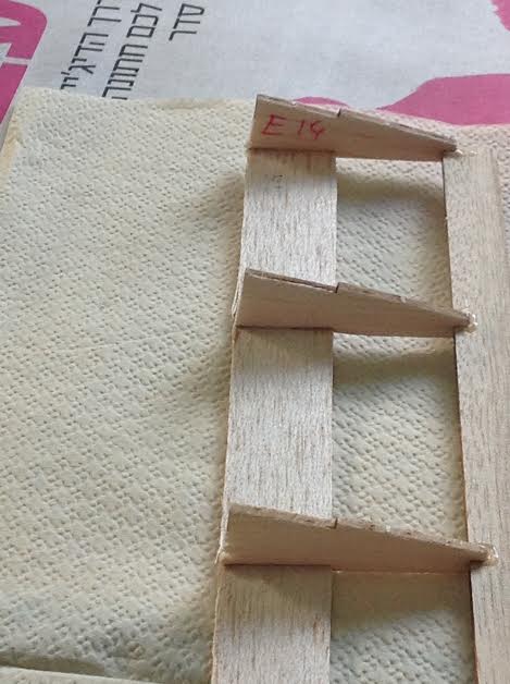
The wing-edge E14 is tucked well into the slot in A10 and is aligned with the the rib (E3).
The wing in the above picture is place upside up so that the notch at the trailing edge is at the bottom (Orange arrow).
This is where I later placed part D2.
Use only a drop of thin CA (Marked with a grey circle)

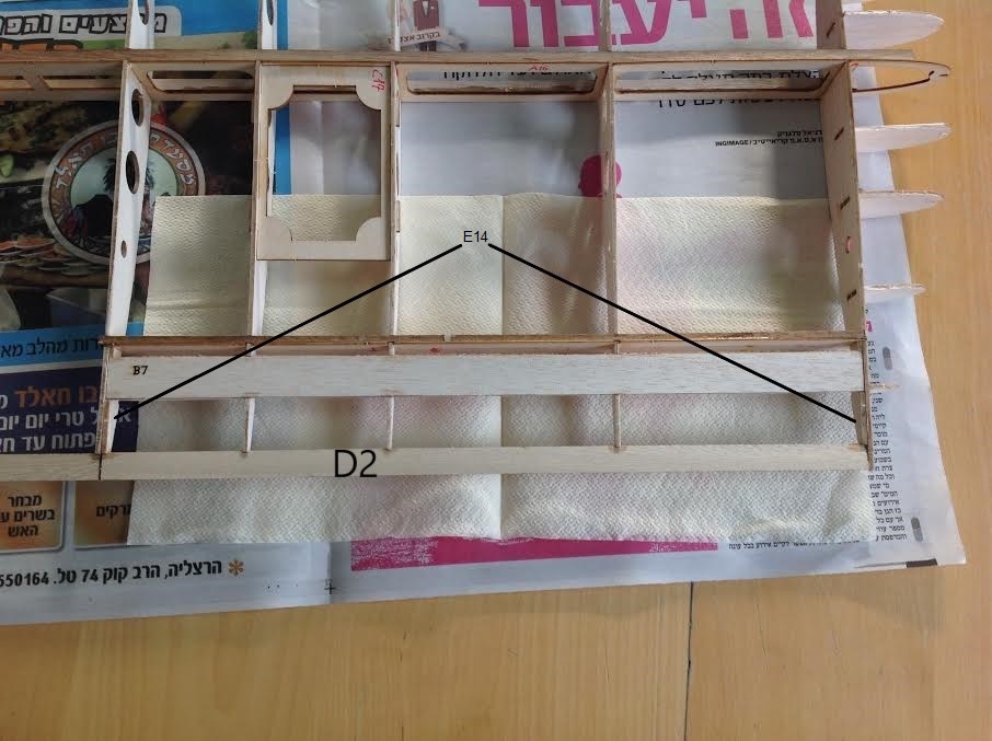
The wing is displayed from above with D2 and B7 glued to place.
Note that they are glued to the three internal ribs and to the two E14 parts.
Be extra cautious not to glue B7, D2 and E14 to the outer ribs (E1 & E3).
Also, I had to shorten B7 so it will fall into place.

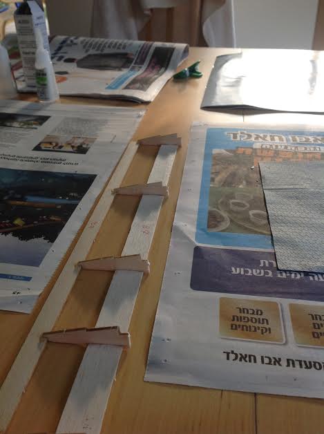
Here is how you cut the ribs and the two E14 parts.

The aileron is detached (One B7 part is missing) as seen from above.
It is not ready to accommodate part G4 yet.

Now the aileron is ready to accommodate part G4

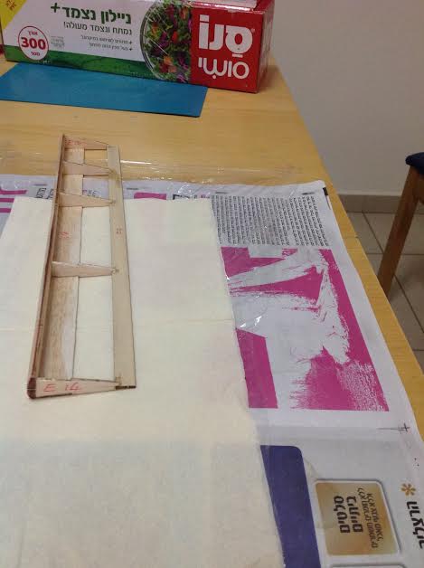
Now the aileron is almost ready. One B7 part is missing and S1 parts are not found yet.
To bevel the G4 was quite a feet but in the end it looks quite good.
Once I complete the creation of this aileron I will post a final post.
Your comments are most welcome.
I have taken some images of the steps so I hope people will find it useful:
1: Insert E14 on the INSIDE ends between ribs E1 and E3. Apply a single drop of CA to the INSIDE edge between the two. The idea here is that the E14 parts are not glued to the sides of the ribs they are butted up against. They will form the outer ends of the aileron.

The wing-edge E14 is tucked well into the slot in A10 and is aligned with the the rib (E3).
The wing in the above picture is place upside up so that the notch at the trailing edge is at the bottom (Orange arrow).
This is where I later placed part D2.
Use only a drop of thin CA (Marked with a grey circle)
2: Glue in D2 along with the bottom B7. Once dry then glue in the top B7.

The wing is displayed from above with D2 and B7 glued to place.
Note that they are glued to the three internal ribs and to the two E14 parts.
Be extra cautious not to glue B7, D2 and E14 to the outer ribs (E1 & E3).
Also, I had to shorten B7 so it will fall into place.
3: Cut both E14 pieces as well as the ribs protruding from A10. Cut them flush with A10. You will now have material on the aileron that you will have to either sand or cut off flush with the leading edge of the two B7 pieces.

Here is how you cut the ribs and the two E14 parts.

The aileron is detached (One B7 part is missing) as seen from above.
It is not ready to accommodate part G4 yet.

Now the aileron is ready to accommodate part G4
4: Install G4 to the leading edge of the aileron and then install the S1 pieces. Note that the S1 pieces are not very well labeled so you may have to "where's Waldo" to find the right lengths to go between the aileron ribs. From there you need to bevel or round off G4 to allow the ailerons to deflect. I would suggest a bevel as it is easier and will be less likely to bind. Just use a sanding block at a 45-degree angle or so and flatted G4 (top and bottom) from the leading edge to the center. This will create a peak at the leading edge akin to a bevel cut in FT terms... but a tad different.

Now the aileron is almost ready. One B7 part is missing and S1 parts are not found yet.
To bevel the G4 was quite a feet but in the end it looks quite good.
Once I complete the creation of this aileron I will post a final post.
Your comments are most welcome.
Attachments
You got it!
TooJung2Die
Master member
I have been following the instructions on how to create a Spacewalker left aileron.
I have taken some images of the steps so I hope people will find it useful:
<snip>
Once I complete the creation of this aileron I will post a final post.
Your comments are most welcome.
That's the way to post build instructions. Good photography and clear instructions. Well done.
Completing the LEFT aileron (No hinges and no covering yet)
Place the on its bottom B7 and place part S1 in place.
It must be the bottom as the control horn will be anchored to it through B7.
Note that is touching both ribs, G4 and B7. I used 5 minute epoxy to glue it into place.

Now I finalised the aileron by placing the upper B7 and gluing it in place using thin CA.
I don't think there's need for strong bonding as the upper B7 has no force applied to it and it will be held in place by the covering.

Thank you @willsonman for your valuable help!
Place the on its bottom B7 and place part S1 in place.
It must be the bottom as the control horn will be anchored to it through B7.
Note that is touching both ribs, G4 and B7. I used 5 minute epoxy to glue it into place.

Now I finalised the aileron by placing the upper B7 and gluing it in place using thin CA.
I don't think there's need for strong bonding as the upper B7 has no force applied to it and it will be held in place by the covering.

Thank you @willsonman for your valuable help!
I'm getting on slowly but surely.
The wings are practically done though inserting the Wing Spar (F5|C9|F5) is impossible, so I'm going to sand it until it fits in. Luckily, I did not apply the top B9,B10 & B6 parts so I can manipulate the inside of the wing. This will enable me to apply glue directly to C23, C21 & C25.
I'd like now to learn what you did with the servo cables. I'm still working on the A8 improvement (I actually copying your work!) but I cannot see where the cables are designed to protrude from the joined wing. Did you pass them between C5 and B9?
I just snaked them through whatever holes in the ribs. I made a small hole at the root of the wing on the top to allow the wires to pass through but be mindful of the fuselage formers as they do not permit wires below them when the wing fully seats. I cut the hole between the two formers. I forget which number. I "winged" it 
Thanks @willsonman !
I should probably note here that the motor I had originally received for this airplane is no longer powering it. While it did fly I was not happy with the performance after getting more acquainted with her. I've since gone to a 0.46 size motor at 670kV. Still on 4S but I'm swinging a 14x7 prop. While this does have much better thrust for getting out of bad situations, it still lacks for a bit more speed I would like to carry through maneuvers. I've ordered a 12x10 prop to help alleviate this. According to eCalc, this should give me another minute of flying time while increasing speed by 10MPH. I'll report back after testing but I think this will be the final power setup.
I got the landing gear done so lets go over the steps...
The part of wire landing gear that is connected to the wing is straight while the wing has a dihadral.
I wander how you managed to square this circle.
Also, I has noticed that you did not put any fibreglass cloth at the root of the wing. I really wandered if this is at all necessary.
No, I did not glass the root but I did use epoxy to join the wings. As the joiners are plenty stout enough to support this size of an aircraft. The gear mount locations are pretty specific with how they are positioned over the internal structure. With the slight dihedral, as the gear was secured, the balsa skin was crushed a little once the nylon straps were secured. Any bending of the struts at the center point is likely to weaken the joints of the wires. As this was very minor, it just made sense.
Maybe a little. But I have had ZERO issues with them and there are a few here who can attest to the beating any gear takes at my field. Old farmland complete with corn row ruts. They are stoutly made.
Had a sad moment yesterday. I forgot to check to make sure I had the right model selected. Takeoff was long and did not seem right in response. As soon as I was airborne, she rolled left to inverted and plowed into the ground upside down. As there are no plans to get parts cut for this, I decided to retire this one. The wing is just a little bit of the damage. The V-stab and rudder are cracked as well and would require re-building. The cowl is crushed and would require extensive glass work to repair. The wing may also have internal fractures... and not really being able to tell without completely re-building the entire wing.
Just over a year with this one and lost due to being a bone-head. Live and learn. Still, she was a very fun airplane to fly. Stable and able to do basic aerobatics.

Just over a year with this one and lost due to being a bone-head. Live and learn. Still, she was a very fun airplane to fly. Stable and able to do basic aerobatics.

Similar threads
- Replies
- 11
- Views
- 983
- Replies
- 6
- Views
- 1K
- Replies
- 0
- Views
- 599
- Replies
- 66
- Views
- 9K


