Split Elevator Control Rod Methods

dmaximob

Junior Member
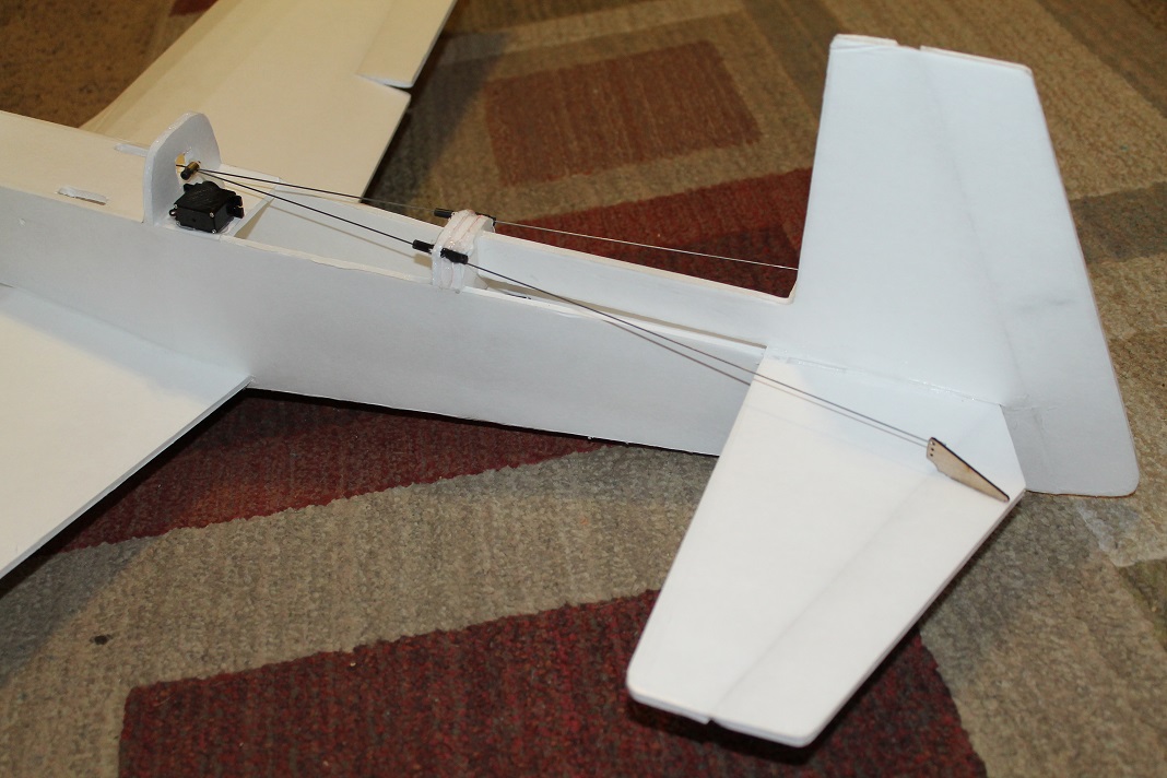
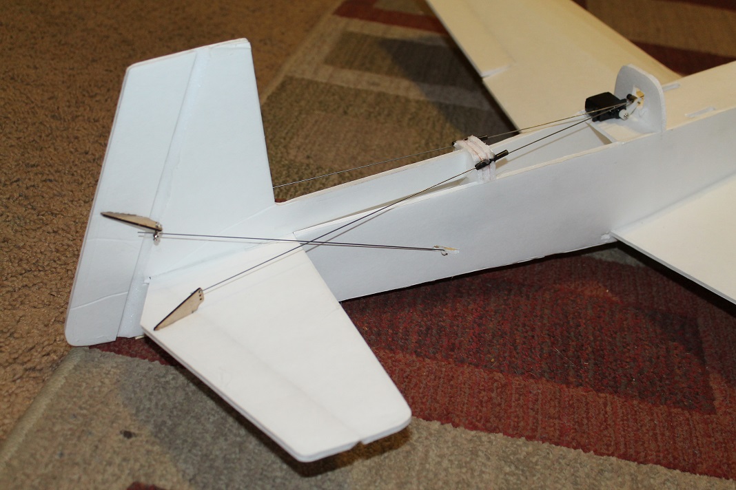
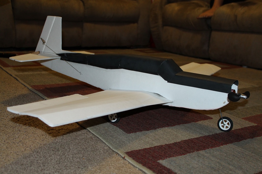
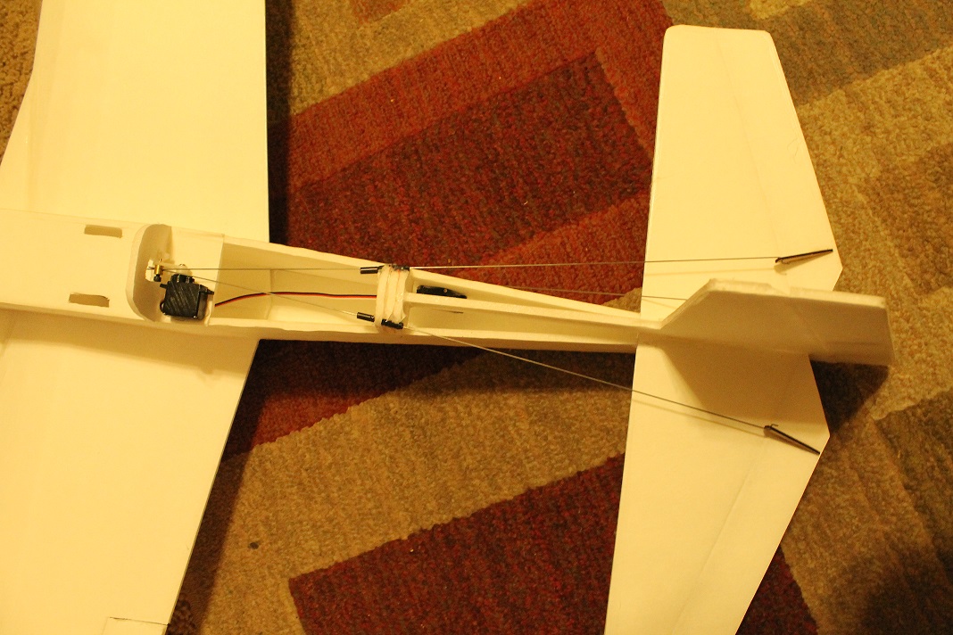
I am in the middle of designing my first scratchbuild plane. I am basically starting with the FT Mustang plans and modifying them a bunch to create a Mooney M20. I've got the fuselage and tail worked out, the wing is going to take me some time to get the leading edge shape right, but the part I'm having a tough time with is the split elevator of the Mooney. I can't quite figure out how I am going to control both sides of the elevator equally.

I've seen a couple methods that seem to look good, but I feel like they take away from the the look of the plane. For example, a BBQ skewer or some rod spanning the entire elevator controlled with a single control rod. I've seen photos of someone who made a 'Y' out of the control rod but I can't quite figure out how to create a solid reliable connection at the 'Y'. I have some reservations about using one servo for each side, but am wiling to do that if necessary.

I was also wondering if there is a such thing as a double linkage stopper. One that I could put on a single servo's arm that has a linkage stopper on both sides of the arm. I've done some looking but haven't found anything like it.

Are there any simple solutions I'm overlooking?

Oh, and maybe the more difficult hurdle is that I want to keep the control surface hinge angles, so I'm not sure if that will limit what I can do.
 

Jaxx

Posted a thousand or more times
Do you mind posting a picture of the elevator, so that we can see what you're working with?
 

dmaximob

Junior Member
Sure,
Here is a sketch of what I have so far. The blue lines are where I'm thinking about putting the control rods.
Screen Shot 2015-02-02 at 6.28.43 PM.png

Here is a plan view of the actual aircraft.
Mooney.jpg
 

Raptortech

Foam Addict
Depending on the metal you decide to use for your control rod, you may be able to solder a Y-joint (or at the very least use epoxy).
 

hotwax

Active member
Hi dmaximob,

you can take a linkage stopper with a 2 mm hole and fit two 1 mm piano wires into.

Or you make one linkage a little shorter, bind and glue / solder it to the longer one in the shape of an Y. That is, if you want to use 1.2 - 1.5 mm piano wire.
 

willsonman

Builder Extraordinare
Mentor
So I go with the the usual KISS method. So you have a little grub screw in a linkage stopper right? Well I just put both control rods in the hole and tighten that grub screw down. If they both will not fit then you can do 2 things: smaller diameter control rods or drill out the hole in the stopper. I've done both but usually I'm drilling out the stopper.

The big point I want to make on this is that USUALLY the tip of the grub screw is pointed. This will drive between the two rods and force them out and still compress them quite well to make them secure. Even if its flat, you will drive them down and against each other to make a nice and tight connection. Do not be afraid to put two rods in one stopper.
 

dmaximob

Junior Member
Thanks guys, your suggestions are helpful. I am probably going to try all of these methods and see what makes me comfortable to fly.
So far the 2 rods in one hole sounds good to me, and the control box looks clever too. I don't know if my soldering skills are good enough to create a reliable 'Y' joint.

It might take me a little while(little ones stealing all my build time), but I'll report back with what I try and what works.
 
Don't sell yourself short on your soldering skills. Get your linkages all setup and where the join wrap the 2 piano wires with thin guage copper wire. Wrap it a little past the 2 wires where its only one wire and put a few wraps arround each leg of the Y to prevent slippage either way. Then fill the copper winds with solder. Ive never had much success soldering piano wire but it jumps right to the copper!
 

rcspaceflight

creator of virtual planes
It looks like servo placement is going to be key. Unless you go with a flexible thin wire and use coffee straws to sleeve it. So it's more like a cable than a rod.

Two servos isn't the ideal solution, but would be the easiest. Trimming could possibly be uneven, but it will certainly work without any issues.
 

dmaximob

Junior Member
OP Delivers!

It's taken 5 months! Wow, where does the time go? I've been busy with kids, working out of town, and building a patio at home, so the design/build has taken me much longer than I ever expected.

For the split elevator I decided to go with a method described by hotwax:
you can take a linkage stopper with a 2 mm hole and fit two 1 mm piano wires into.

I decided to solder the two rods where they meet in the linkage stopper. An unexpected side effect was the servo control arm melting quite a bit. It still works fine though. I also added some coffee straw sleeves where the wires exit the fuselage.

I am pleased with how things turned out and with this being my first design(modified plans) I learned a lot.

A few notes:
- I had a tough time trying to fit the servo lower since I already glued the fuselage in place. Next time I am going to plan ahead more and place the elevator rods under the horizontal stabilizer.
- I also think things would be much more simple with a spar joining both elevators. It is tempting to do this method, but I enjoyed the challenge of leaving them split.
- In general, there are a handful of things I can refine as far as getting the thing to look more close to the shape of the Mooney.
- I gained a lot more respect for the flite test crew and anyone else who designs planes. The amount of work it takes to get everything to fit right was surprising for me.

I am going to test fly it this weekend. I am not expecting a smooth maiden, but am looking forward to seeing how my work turned out.

Thanks for all the advice!
 

Attachments

  • IMG_9760.JPG
    IMG_9760.JPG
    203 KB · Views: 9
  • IMG_9761.JPG
    IMG_9761.JPG
    212.2 KB · Views: 11
  • IMG_9763.JPG
    IMG_9763.JPG
    202.2 KB · Views: 7
  • IMG_9758.JPG
    IMG_9758.JPG
    258.8 KB · Views: 12

Corbarrad

Active member
Two control rods into one linkage stopper works fine on my fms bf 109.
The bf 109 fun fighter even has the z-bends of the two linkages in adjacent holes on the servo horn.
That had me concerned about uneven throws, first but it's worked flawlessly so far.

Am I partial to a certain WW2 warbird? I suppose you might get that impression...
 

dmaximob

Junior Member
I was able to maiden over the weekend and it was awesome!

Unfortunately, I don't have a camera set up to record my flights. Still, it was a decently windy day, with frequent gusts. I showed up to the field as one pilot was leaving with his Apprentice in pieces.

I had to trim a few clicks, but once I got it dialed in it was a blast to fly. It handles similarly to the FT Mustang, from what I remember. It handles slow speeds well and can really roll and turn with speed. I've only ever flown tail draggers, so it was quite the feeling to land with a definite touchdown.

The only casualty was a broken prop on a sketchy landing. It's tough to tell from the photos but there is only about 3/8" clearance from the ground to the prop. I did not notice any issues with the elevator situation, which was a relief.

I'm really into this model, it is a joy to fly something of my own. I'll be working on Version 2.0 over the next who knows how many months. Until then, thanks again for all of your input on the elevator.