'Stik' Plane

Mad_Mechanic

Well-known member
So the other night I was watching the old Flite Test video on the eRC Micro Stik and I thought it was pretty cool. So I started looking into parts and ideas of how I could build an FT inspired 'Stik' plane.

Today on my lunch break I threw together this design in SolidWorks. It's based around a 1/2" wood dowel (thinking something like Pine or Basswood), wing and control surfaces are dollar store foam board. If my estimations are correct, I can get all the wing and tail surfaces from 1 piece of foam board.
Stik Iso.PNG

Wings have nominally 5-deg dihedral on each side.
Stik Front.PNG

Wingspan is nominally 24in, with an 8in wide elevator (1/3 wingspan) and 4in tall rudder (1/2 elevator).
Stik Top.PNG

I'm letting SolidWorks do all the math for the CG. The foamboard density I used was 0.062 g/cm^3. All the electronics bits I applied the manufacturer's stated weights. I was aiming for the balance point to be about 1/3 back from the leading edge. I chose 1/3 because that's what Josh Bixler says he uses for most of his designs.
Stik Side with CG.PNG

Electronics are as follows:
FrSky RX4R receiver (4-channel, ~2.4g)

2x HexTronik HXT500 servos (~6.2g each)

Turnigy 1811-2000Kv motor (~11g)

Turnigy Plus 6A ESC w/ BEC (~6g)

Turnigy 2s 460mAh LiPo (~31g)
*Was planning on a 300mAh, but I needed more nose weight

Here is how all the electronics package:
Stik Electronics.PNG

The motor description states that it will work with 6x3 up to 7x3 props with a nominal thrust of 150-165g

According to SolidWorks mass calculations, I'm right around 135g as shown. This of course doesn't account for hot glue, which I will have to use sparingly.

I already have most of the electronics parts on order from the HobbyKing USA warehouse, unfortunately the motor is currently on backorder so I can't get to excited.

Thoughts?
 

Mad_Mechanic

Well-known member
I think this just turned into an official build thread and not just a concept proposal. Yesterday I generated flat patterns for everything except the wing and got busy with the dollar store foamboard.

Patterns:
DSC06764.jpg

Parts cut:
DSC06766.jpg

Electronics cavity:
DSC06765.jpg

Tail Assembly:
DSC06767.jpg

So far so good, I need to figure out how I'm going to print and cut the wing sections. The wing is small enough it could be cut as 1 part from a sheet of foam board, or I can keep it as two pieces. Either way I'm going to have to use tiled plans or find someone with a large format printer.

I also need to buy the dowel.
 

Mad_Mechanic

Well-known member
Another update! This time it's more electronics stuff, because I had orders come in.

So I have a slight change to the bill of materials. The motor is now a Cobra Motors C-2202/70, kv = 1530. This will swing either an APC 7x4SF or 7x5SF. The reason for this is mainly because HobbyKing doesn't look to be getting a shipment of the motor I originally wanted. The upshot here is that the motor should be a tad more powerful, the downside is it's a tad heavier.

I also decided to use a different ESC. I was going to use either a Turnigy Plush 6A or 10A, but now I'm going to use a PowerUp 10A from Aloft hobbies. This is only 2g heavier than the Plush 10A at 11.1g, but it comes with an SBEC that can support 5A @ 5V which is nice. The SBEC should also be a bit more energy efficient than the linear BEC the Plush ESC uses.

I also got the Hextronik HXT500 5g servos in.

The electronics cavity with servos, receiver and BBQ skewers is around 20g weight, but I haven't glued the servos in place yet so that will change things slightly.

I'm also opting to use XT30 connectors for the battery instead of the JST the LiPo battery came with.
DSC06792.jpg

DSC06773.jpg

DSC06791.jpg
 

Mad_Mechanic

Well-known member
Ok, so where am I at on this project?

I am at the point where I need to print the pattern for the wing and make the wing.

I also bought the dowel but I'm trying to figure out the best way to carve out the recesses/reliefs for the electronics box and the tail section.

I think for mounting the motor I'm going to glue an FT firewall to the end of the dowel. I have extras of these firewalls and it saves me a little bit of R&D.

Why haven't I finished this project yet? Well, because I've had a lot of doctor's appointments and medical issues in the last few months that have been consuming much of my time.
 

Mad_Mechanic

Well-known member
Ok, so this is a little bit of thread necro but please forgive me. I don't want this project abandoned.

As I wrapped up the prototype design work for my 1-sheet plane I remembered that I never finished the print layout for the wing section of this project. So I finished the wing layout for printing and made a PDF which I'm attaching here. Again this is prototype for print adn use at your own risk. Many lines are not fully defined as to their purpose (partial or thru cut). You have been warned.

I am planning to get these plans printed at the same time as my 1-sheet plane plans.
 

Attachments

  • Stick Plane - Foam Board Layout.PDF
    118.8 KB · Views: 0

Mad_Mechanic

Well-known member
MUCH progress was made on this project over the weekend, this will take several posts to cover but I now have a prototype that is nearly ready to fly, as soon as I get some servo pushrods.

So over the weekend I got the full plans printed at Staples and I cut out the pieces.

DSC06857.jpg


Next I did the wing assembly. This is 'classic' Flite Test folded wing design.

DSC06858.jpg


DSC06859.jpg


I also added some packing tape to the center seam/fold of the wing. I also assembled the electronics cavity (B-fold) and the tail pieces. All very simple.

DSC06860.jpg
 

Mad_Mechanic

Well-known member
Next I stuffed the electronics cavity and added dowels to allow the wing to be attached via rubber bands. I reinforced the foamboard edges with hot glue spread thin and the dowels are glued in place with Gorilla super glue (CA glue).

DSC06861.jpg


I attached the electronics cavity to the dowel (now a 1/'2 inch square dowel) 3.5-in back from the nose. the cavity is first affixed with a small bead line of hot glue and then the corner seams between dowel and cavity are reinforced with CA glue.

DSC06863.jpg


DSC06864.jpg
 

Mad_Mechanic

Well-known member
Next I attached the tail surfaces. Not much to this, just another thin bead of hot glue and more CA glue around the edge seams.

DSC06865.jpg


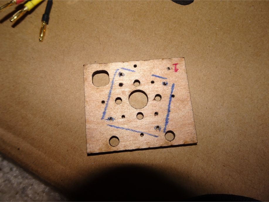
Next I needed a motor mount. I'm using a Cobra C2202/70 (1530 kV), it uses a mounting screw pattern that the FT firewalls don't support. But the motor comes with wood screws so I rotated the motor on the FT firewall and drilled new pilot holes. Next I trimmed the FT wirewall down with a pair of sharp scissors. I eyeballed center of the motor shaft on center with the dowel, I think I got close enough. A thin layer of hot glue on the end of the dowel and then a smearing of CA glue around the back edges between the dowel and the firewall.

DSC06867.jpg


DSC06868.jpg


DSC06869.jpg


DSC06870.jpg


DSC06871.jpg


DSC06872.jpg
 

Mad_Mechanic

Well-known member
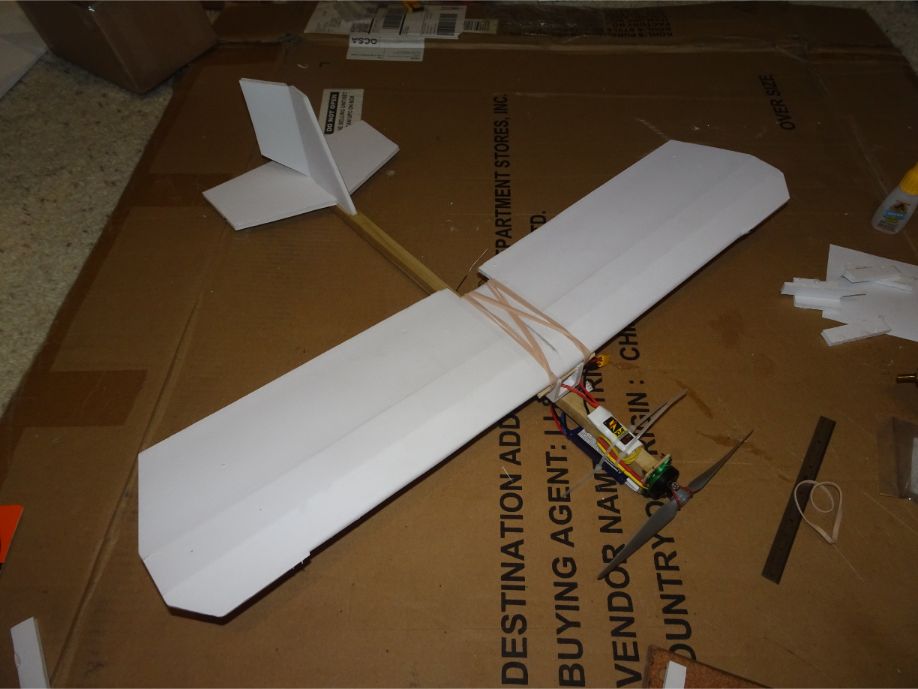
The last thing I could do on Saturday was rubber band on the wing, add a battery and give it a glide test. Battery is a Turnigy 2s 460mAh.

Glide test was very encouraging, and the plane balances on the wing spar, which is what I was hoping for.

DSC06873.jpg


The white chunk of foam board between the firewall land the battery is to protect the battery from being punctured by the motor mount screws that protrude out behind the firewall. It also makes for a good battery placement guide.
DSC06874.jpg
 

Mad_Mechanic

Well-known member
So, at this point I'm waiting for a couple things.

First is the pushrod stock I ordered from Aloft Hobby. The next is a battery charger I ordered from the Flite Test/Amain store as well as XT-30 charge leads I ordered from HobbyKing.

If everything arrives on time, I'm hoping to maiden this plane this weekend.
 

Mad_Mechanic

Well-known member
Here it is, video of my maiden flight (flights?).

Went ok, it's a light plane and there was a little bit of a wind that would come and go. Doesn't take much damage when it crashes.


TooJung2Die

Master member
It looks tail heavy to me and I think you can use bit more dihedral for RET. Keep trying. You're so close. Do you have an Archery shop near you? I went to one and asked if they had any scrap arrows. After I explained what I wanted them for and wouldn't shoot them he showed me a huge box of worn out graphite/carbon fiber arrow shafts. He gave me a big handful for free. They make an excellent stick fuselage or boom tail. Lighter than wood and a lot stiffer.
 

Mad_Mechanic

Well-known member
It looks tail heavy to me and I think you can use bit more dihedral for RET. Keep trying. You're so close. Do you have an Archery shop near you? I went to one and asked if they had any scrap arrows. After I explained what I wanted them for and wouldn't shoot them he showed me a huge box of worn out graphite/carbon fiber arrow shafts. He gave me a big handful for free. They make an excellent stick fuselage or boom tail. Lighter than wood and a lot stiffer.

Thank you for the suggestion, I may look to see if there is an archery range/shop near my house. As far as I know there isn't one though.

I'm going to stick with the wood dowel for the time being as I tweak the design. One of my design goals here was to keep with easily/readily available materials. I know the wood dowel is going to be considerable weight compared to a fiberglass or carbon fiber rod, but I'd like to get my original concept working.

Rather than add more nose weight, I think if I build a new "fuselage" and move the main electronics cavity/wing mount back a little I can get the balance better. Not like this is a time consuming build. This also will have the benefit of shortening the control rods slightly.

Thank you for the suggestions and feedback!