Cyberdactyl
Misfit Multirotor Monkey
There’s been one aspect of all multirotors that has nagged me for some time.
And that is the insouciant concern for thrust column efficiency (TCE). Most builders take little notice of TCE, in that they design and build mostly for a handful of other reasons. Several commercial multirotors designers ignore this aspect as well. Many designers concern themselves with a single or combination of, initial cost, crash repair cost, crash management, size, weight, payload capacity, materials at hand, what they’ve seen before, etc. Rarely, if ever, is TCE even a consideration.
This is surprising in that low TCE can reduce flight time and lift capacity by as much as 25%. Most plate-type booms are in the neighborhood of 15%. Many configurations aggravate the TCE by placing the ESC flat, directly in the highest cross-section of thrust. Many place holes in the booms, however that is most likely for weight reduction, and the result is turbulence, buying very little increased lift.
But to give credit where credit is due, clean carbon fiber round booms have outstanding TCE. But I suspect CF tubes are chosen mostly for weight/strength consideration. However, even square wood, aluminum or carbon fiber booms have decent efficiency. Square booms do have a maximum thrust splash area, in that the leading edge is flat, but since a square tube or solid boom has a relatively small planform area, the thrust splash does not move into a critical region of gross inefficiency overall. I have seen double plates turned vertical, but generally the boom has horizontal structure between the plates, such as screws, standoffs, etc., to improve rigidity.
So, setting aside those designs which are either excellent or passable in TCE, I want to experiment with a paradigm shifting idea. To step beyond even the round clean carbon fiber boom, and get the TCE as close to 100% as is possible, by turning the grossly inefficient common flat boom vertical.
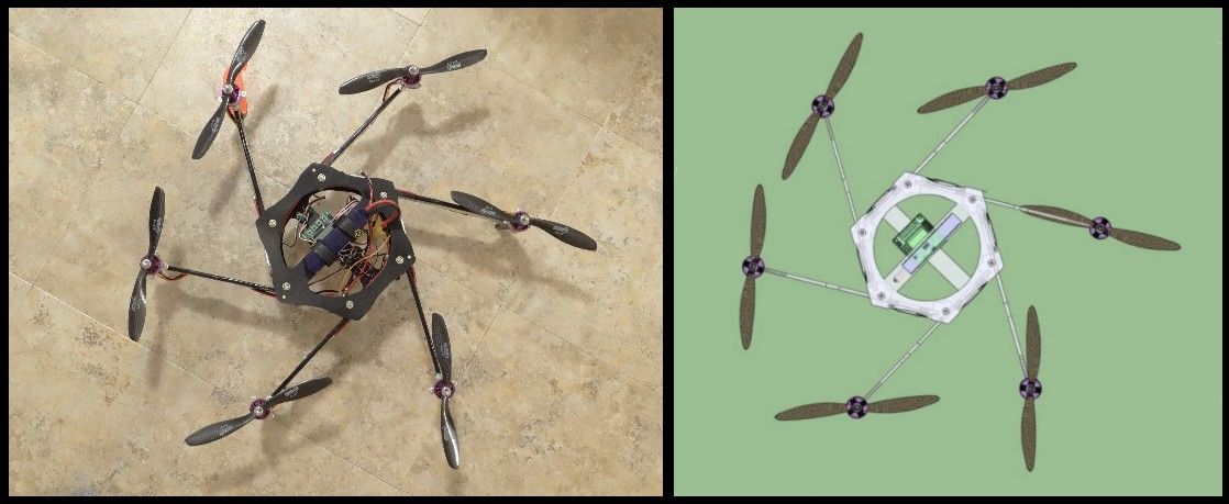
The idea was sparked by my ‘Racing Quad’ design I did several months ago. It basically utilized a symmetric shallow chord airfoil shape as the booms. It then occurred to me, if the boom could be made stiff enough, a simple flat plate could be used and could be built much easier and cheaper. So I began to design from that aspect.
The following hexicopter is made from 3/16” plywood for the booms and 5/32” plywood for the main plates.
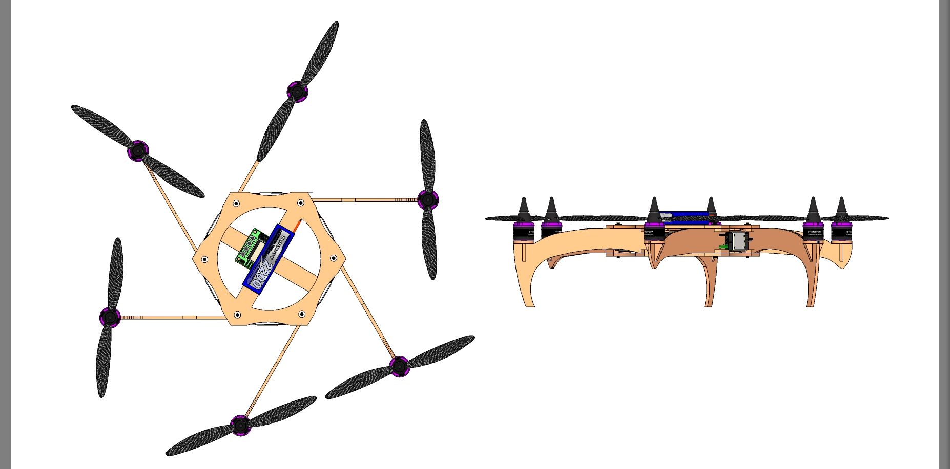
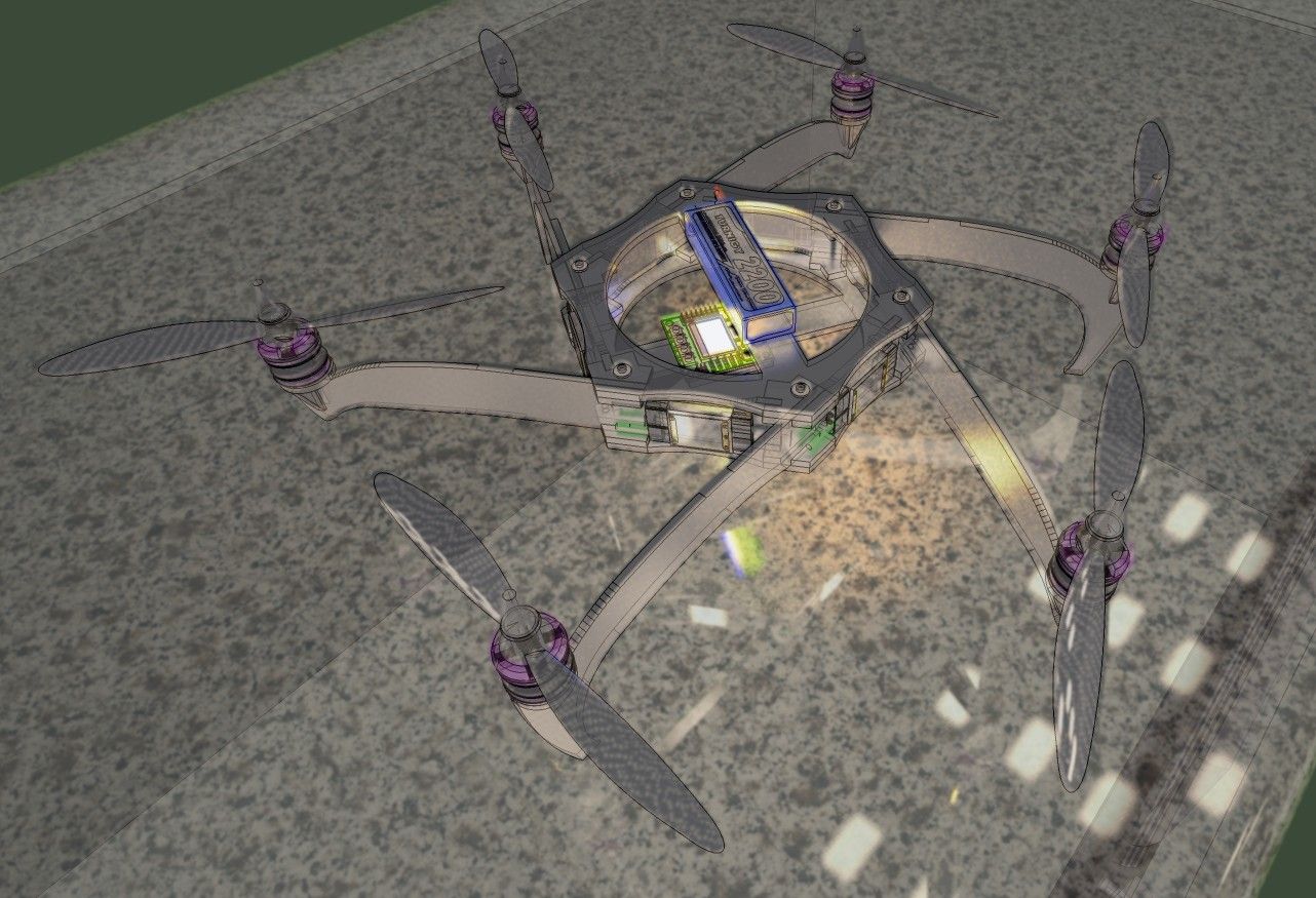
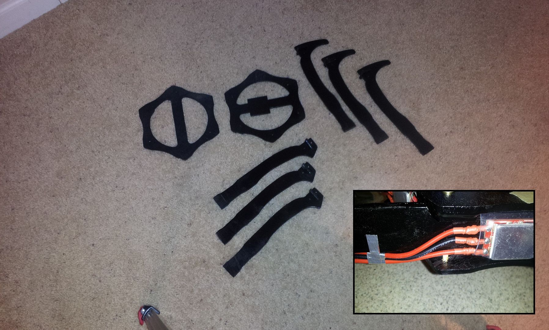
I started by designing my general idea in SketchUp, then tweaking and changing several times until I had a rough structure, then trimmed the main plate and booms down to a size that was not too overly bulky given I was using an average strength material. I then printed out the shapes and spray adhered them to the plywood and cut them out with a band saw.
I coated the area of most active boom flex with epoxy, essentially adding a ~0.6mm non-reinforced rigid membrane tube.
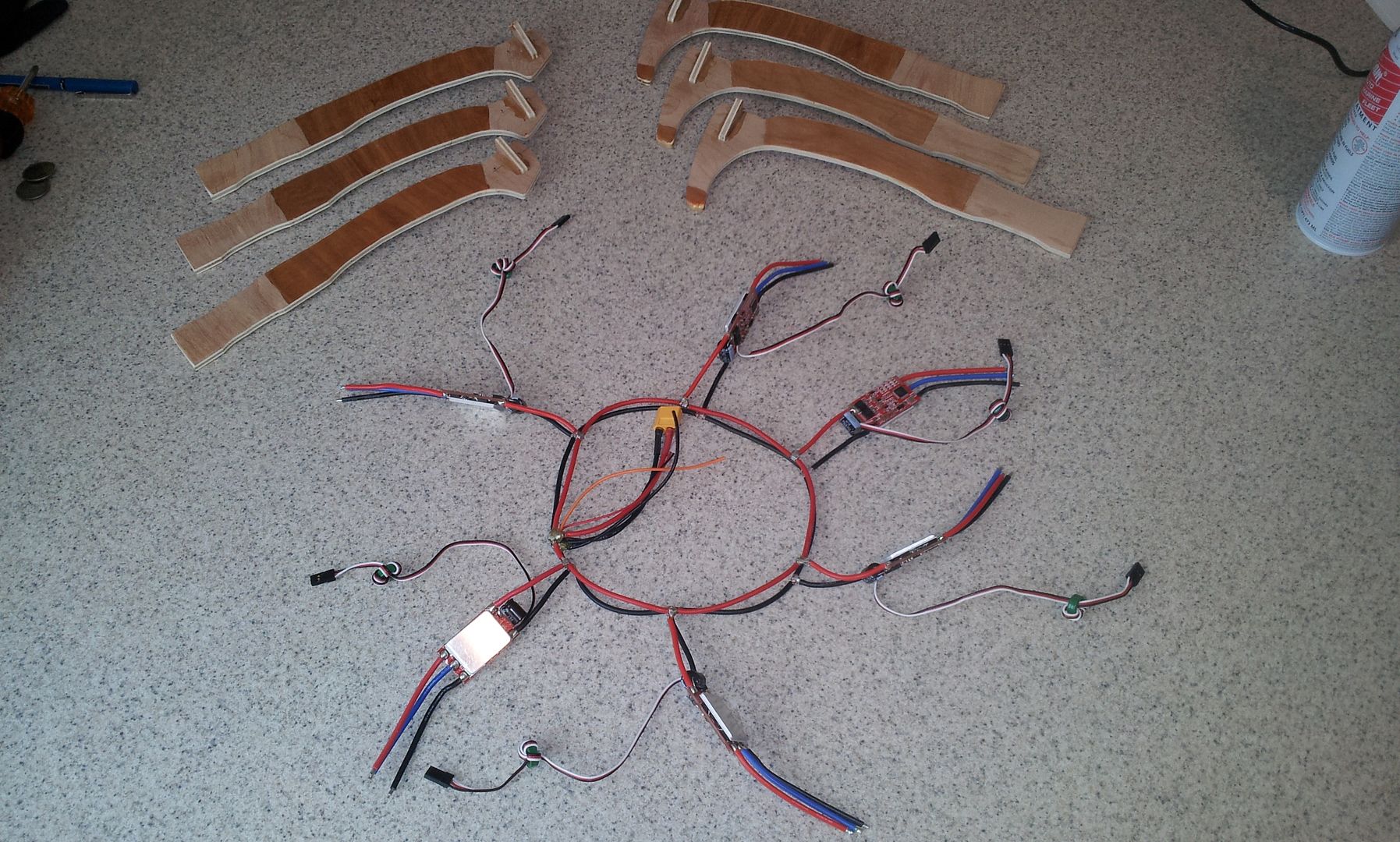
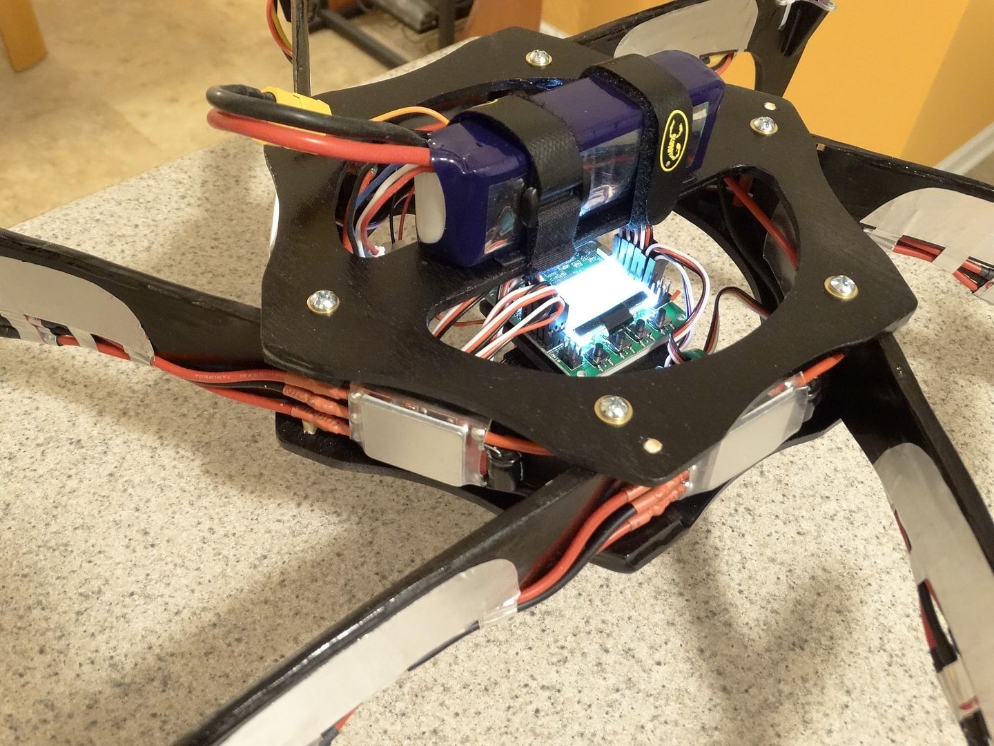
I made a common ring-type harness. All connections are splayed wire T interface connections with a fine copper wire wrapping, then soldered and double coated with epoxy.
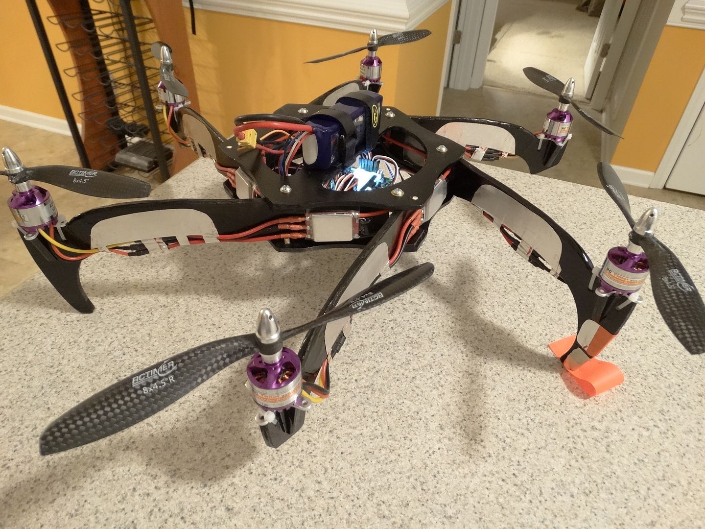
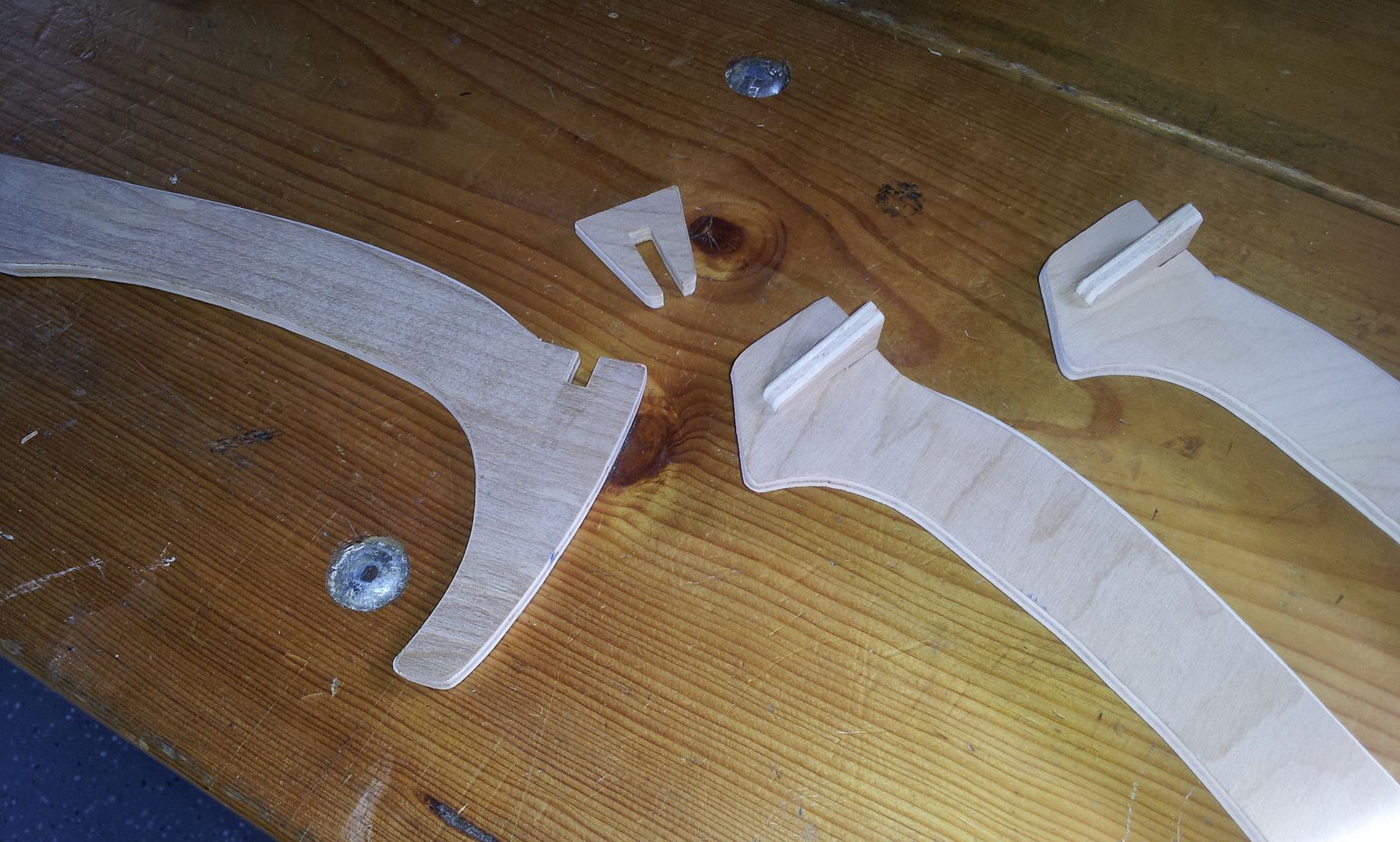
I suspect the reason why this design has not been done before, (at least I have yet to see it) is the problematic mounting of the motors on a very thin vertical plate. My solution is straightforward and simple. I used interlocking pieces, wood glued the pieces and reinforced them with two coats of epoxy on the surface. I also did not use the cross piece to zip-tie the motors down. They are only for lateral support, so there is no constant upward pull, or jerk moments on the piece, only compression.
Mounting the vertical booms to the frame is easy. I made blocking tabs and guides at every other corner, and did the same on the opposing plate, offset by a corner, so all corners have blocking and guide rigidity either above or below.
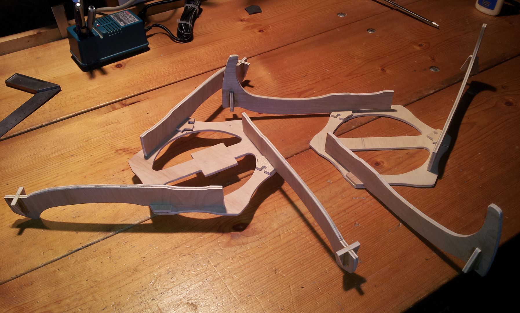
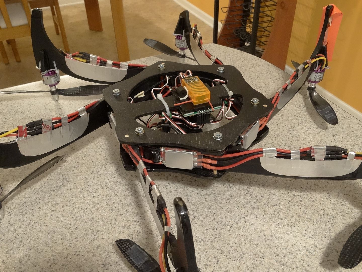
The two halves apart that are pressed together and securely clamped with six screws.
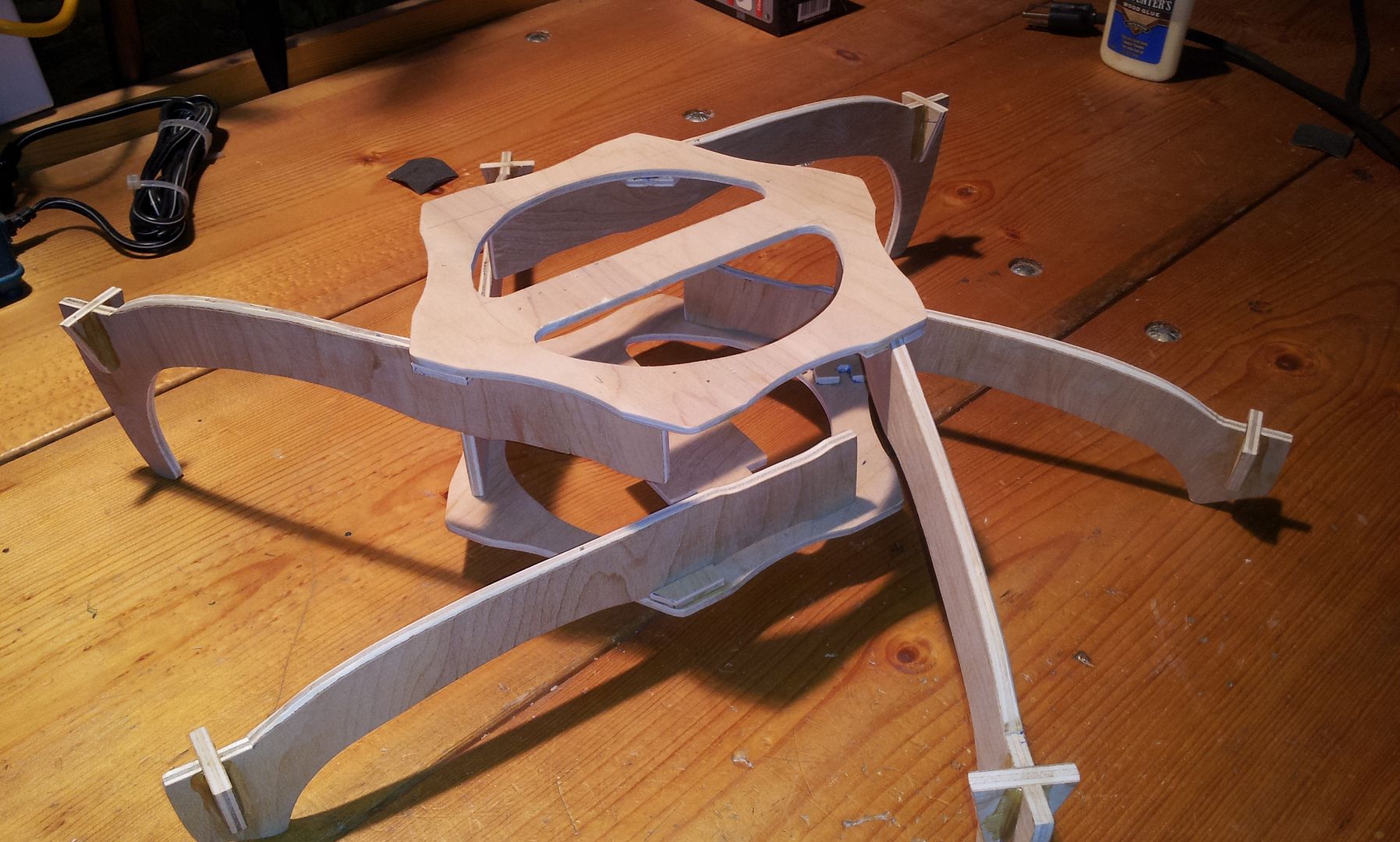
The result is an amazingly strong and rigid six sided box structure that can withstand dozens of kilos of shear, trapezoidal force.
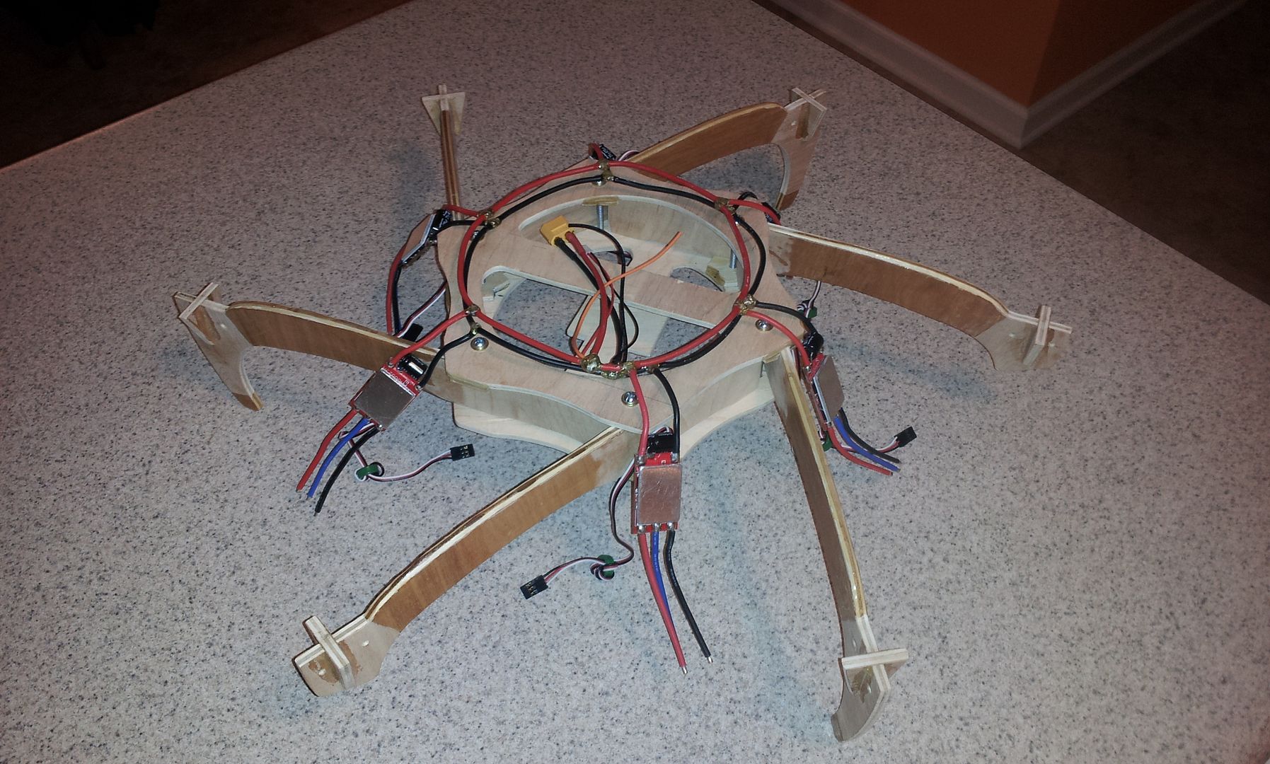
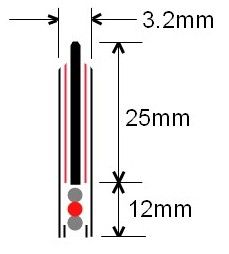
I’m also utilizing clear shrink as my ESC mounting material. I’ve indented the booms so that the shrink does not interfere with the clamp region near each fastener, and to allow higher PSI at the clamp points and to allow the shrink to move freely during the heating process.
I’ve recessed the KK2.1 ‘inside’ the ring for protection and also recessed it back, off center about 20mm, so the Invensense chip is as close to the center of lift and the CG as possible. The battery is mounted on top to put the elevation CG closer in-line with the lift plane. The result is the elevation CG is about 1cm below the lift plane. I mounted the Rx underneath since I used foil tape to affix the motor wires to the booms and did not want to reduce reception by having the Rx and Tx LOS interfered at great distances. Foil tape is extremely strong in uniform tension, but yields easily when tearing.
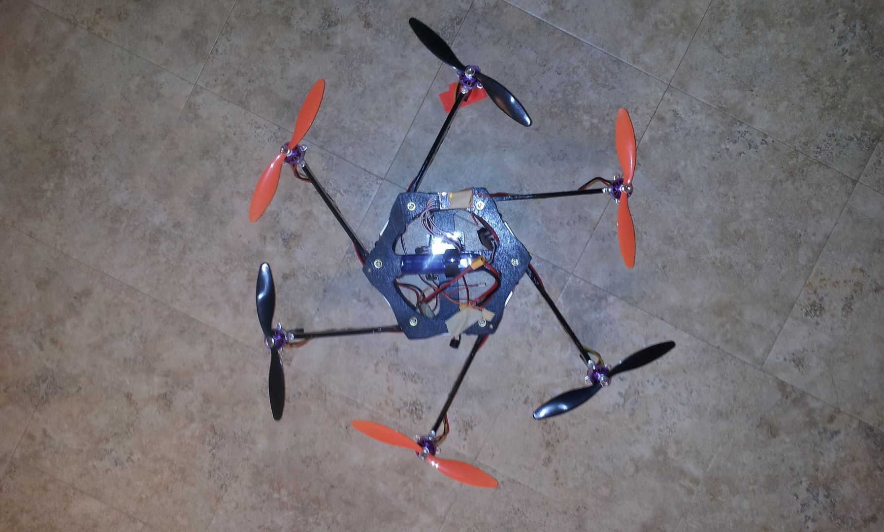
Next came some rattle-can black and putting it together. Both went fast. I was a little worried I would need three hands to wrestle to manipulate it all, but it went together much easier than I thought. Having a block and guide only on one surface at each corner allowed me to slide and rotate each boom into position easily. Another aspect of such a design is I can slightly rotate each boom a degree or so for perfect vertical alignment before clamping down hard with the screws. One post design change I made was adding small wood pins on the outside corner where the boom is merely clamped and not blocked. I added the pins as reassurance against a catastrophic mishap if the clamping screws worked loose. I will loctite them as well.
Last in the build was the organization of the wiring. Most important, this included stacking the motor wires under the 'trailing edge' of the booms. I also rounded the 'leading edge' or top of the boom to reduce the splash obstruction. I've yet to get the wiring 'looking good' along the trailing edge, but that will be done soon.
If this design proves itself, and so far it flies outstandingly well, I may remake it with 2.0 and 2.5mm G10. That would drop the frame weight by half, which is currently 415g (with screws). As is, the AUW is just under 1180g with 4S. So I suspect I could get a G10 hex of this configuration down to a AUW of around 925g. I would also fix the booms in place by incorporating the slot and tab technique used in most frame plate and boom designs. I almost did use such on this one, but wanted to retain a nice clean upper plate for esthetics and gluing blocks and guides were easier, faster and required less precision. And of course, making the boom even thinner would shave off another percent or so of thrust column obstruction, increasing the TCE that much more.
The final calculation tells me, while this hex has six booms, it has only 20% more planform obstruction in the thrust column as the already excellent thrust column efficient 10x10mm carbon fiber boom tricopter , and only ~75% of the splash obstruction.
And before someone mentions it, yes... I did strongly consider adding a raised mini bulge texture to the boom surface. The air velocity is high enough, as well there is enough vertical surface area to make it worthwhile. The technique I considered would have been laying a hex-shaped screen with openings of around 2mm across the flat of the boom, then buttering 15 minute epoxy across the screen. Waiting until the epoxy had set to a rather firm gummy consistency, then gently lifting off the screen. Allowing enough time to for the hex-shaped 'mounds' of epoxy to flow, round and harden to a nice mound. This uniform texture would improve the TCE by improving the boundary layer off the boom, as well as serve as the stiffener tube. This is something that would require extra effort, or similar could easily be done on the boom material itself during a mass produced manufacturing process.
My initial maiden was a crash. But purely because of my confusion. I connected everything up rather late one night and since the ESC power and control wiring 'appeared' to come from the end of the boom's motor, because of the way the booms are inserted, (LOL even though I designed it) I inadvertently hooked them up offset by 60 degrees. It did this weird Euler's Disk thing and the flight lasted about a second.
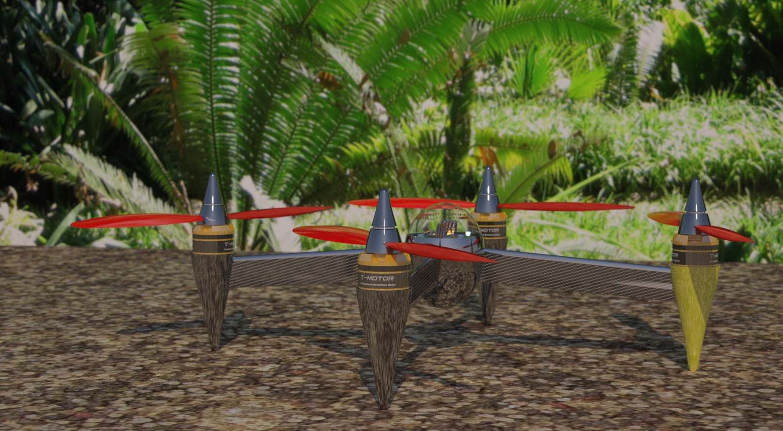
Of course, the most important feature is, how does it fly when properly connected? So far, better than I imagined! Rock solid and liquid smooth off of Steveis' stock setting of 1.11S2.
Please excuse the crude taping of the stacked motor leads on the trailing edge and the orange orientation tape. As to the slow fly props, I will switch to carbon fiber as my confidence grows flying it. I will also do a much better job of affixing the wires now that I know it flies great.
And that is the insouciant concern for thrust column efficiency (TCE). Most builders take little notice of TCE, in that they design and build mostly for a handful of other reasons. Several commercial multirotors designers ignore this aspect as well. Many designers concern themselves with a single or combination of, initial cost, crash repair cost, crash management, size, weight, payload capacity, materials at hand, what they’ve seen before, etc. Rarely, if ever, is TCE even a consideration.
This is surprising in that low TCE can reduce flight time and lift capacity by as much as 25%. Most plate-type booms are in the neighborhood of 15%. Many configurations aggravate the TCE by placing the ESC flat, directly in the highest cross-section of thrust. Many place holes in the booms, however that is most likely for weight reduction, and the result is turbulence, buying very little increased lift.
But to give credit where credit is due, clean carbon fiber round booms have outstanding TCE. But I suspect CF tubes are chosen mostly for weight/strength consideration. However, even square wood, aluminum or carbon fiber booms have decent efficiency. Square booms do have a maximum thrust splash area, in that the leading edge is flat, but since a square tube or solid boom has a relatively small planform area, the thrust splash does not move into a critical region of gross inefficiency overall. I have seen double plates turned vertical, but generally the boom has horizontal structure between the plates, such as screws, standoffs, etc., to improve rigidity.
So, setting aside those designs which are either excellent or passable in TCE, I want to experiment with a paradigm shifting idea. To step beyond even the round clean carbon fiber boom, and get the TCE as close to 100% as is possible, by turning the grossly inefficient common flat boom vertical.
The idea was sparked by my ‘Racing Quad’ design I did several months ago. It basically utilized a symmetric shallow chord airfoil shape as the booms. It then occurred to me, if the boom could be made stiff enough, a simple flat plate could be used and could be built much easier and cheaper. So I began to design from that aspect.
The following hexicopter is made from 3/16” plywood for the booms and 5/32” plywood for the main plates.
I started by designing my general idea in SketchUp, then tweaking and changing several times until I had a rough structure, then trimmed the main plate and booms down to a size that was not too overly bulky given I was using an average strength material. I then printed out the shapes and spray adhered them to the plywood and cut them out with a band saw.
I coated the area of most active boom flex with epoxy, essentially adding a ~0.6mm non-reinforced rigid membrane tube.
I made a common ring-type harness. All connections are splayed wire T interface connections with a fine copper wire wrapping, then soldered and double coated with epoxy.
I suspect the reason why this design has not been done before, (at least I have yet to see it) is the problematic mounting of the motors on a very thin vertical plate. My solution is straightforward and simple. I used interlocking pieces, wood glued the pieces and reinforced them with two coats of epoxy on the surface. I also did not use the cross piece to zip-tie the motors down. They are only for lateral support, so there is no constant upward pull, or jerk moments on the piece, only compression.
Mounting the vertical booms to the frame is easy. I made blocking tabs and guides at every other corner, and did the same on the opposing plate, offset by a corner, so all corners have blocking and guide rigidity either above or below.
The two halves apart that are pressed together and securely clamped with six screws.
The result is an amazingly strong and rigid six sided box structure that can withstand dozens of kilos of shear, trapezoidal force.
I’m also utilizing clear shrink as my ESC mounting material. I’ve indented the booms so that the shrink does not interfere with the clamp region near each fastener, and to allow higher PSI at the clamp points and to allow the shrink to move freely during the heating process.
I’ve recessed the KK2.1 ‘inside’ the ring for protection and also recessed it back, off center about 20mm, so the Invensense chip is as close to the center of lift and the CG as possible. The battery is mounted on top to put the elevation CG closer in-line with the lift plane. The result is the elevation CG is about 1cm below the lift plane. I mounted the Rx underneath since I used foil tape to affix the motor wires to the booms and did not want to reduce reception by having the Rx and Tx LOS interfered at great distances. Foil tape is extremely strong in uniform tension, but yields easily when tearing.
Next came some rattle-can black and putting it together. Both went fast. I was a little worried I would need three hands to wrestle to manipulate it all, but it went together much easier than I thought. Having a block and guide only on one surface at each corner allowed me to slide and rotate each boom into position easily. Another aspect of such a design is I can slightly rotate each boom a degree or so for perfect vertical alignment before clamping down hard with the screws. One post design change I made was adding small wood pins on the outside corner where the boom is merely clamped and not blocked. I added the pins as reassurance against a catastrophic mishap if the clamping screws worked loose. I will loctite them as well.
Last in the build was the organization of the wiring. Most important, this included stacking the motor wires under the 'trailing edge' of the booms. I also rounded the 'leading edge' or top of the boom to reduce the splash obstruction. I've yet to get the wiring 'looking good' along the trailing edge, but that will be done soon.
If this design proves itself, and so far it flies outstandingly well, I may remake it with 2.0 and 2.5mm G10. That would drop the frame weight by half, which is currently 415g (with screws). As is, the AUW is just under 1180g with 4S. So I suspect I could get a G10 hex of this configuration down to a AUW of around 925g. I would also fix the booms in place by incorporating the slot and tab technique used in most frame plate and boom designs. I almost did use such on this one, but wanted to retain a nice clean upper plate for esthetics and gluing blocks and guides were easier, faster and required less precision. And of course, making the boom even thinner would shave off another percent or so of thrust column obstruction, increasing the TCE that much more.
The final calculation tells me, while this hex has six booms, it has only 20% more planform obstruction in the thrust column as the already excellent thrust column efficient 10x10mm carbon fiber boom tricopter , and only ~75% of the splash obstruction.
And before someone mentions it, yes... I did strongly consider adding a raised mini bulge texture to the boom surface. The air velocity is high enough, as well there is enough vertical surface area to make it worthwhile. The technique I considered would have been laying a hex-shaped screen with openings of around 2mm across the flat of the boom, then buttering 15 minute epoxy across the screen. Waiting until the epoxy had set to a rather firm gummy consistency, then gently lifting off the screen. Allowing enough time to for the hex-shaped 'mounds' of epoxy to flow, round and harden to a nice mound. This uniform texture would improve the TCE by improving the boundary layer off the boom, as well as serve as the stiffener tube. This is something that would require extra effort, or similar could easily be done on the boom material itself during a mass produced manufacturing process.
My initial maiden was a crash. But purely because of my confusion. I connected everything up rather late one night and since the ESC power and control wiring 'appeared' to come from the end of the boom's motor, because of the way the booms are inserted, (LOL even though I designed it) I inadvertently hooked them up offset by 60 degrees. It did this weird Euler's Disk thing and the flight lasted about a second.
Of course, the most important feature is, how does it fly when properly connected? So far, better than I imagined! Rock solid and liquid smooth off of Steveis' stock setting of 1.11S2.
Please excuse the crude taping of the stacked motor leads on the trailing edge and the orange orientation tape. As to the slow fly props, I will switch to carbon fiber as my confidence grows flying it. I will also do a much better job of affixing the wires now that I know it flies great.
Last edited: