Twin EDF Concept aka the "Thunderjet"

Geniuslike

New member
So my first introduction to RC airplanes many, many years ago was the so called "Thunderjet" by Silverlit. (Those not familiar, most silverlit airplanes are two channel, twin engined, thurst vectoring toys with brushed motors) It provided me many hours of fun, and to my surprise, it even flew upside down without any issues (not that it could do a loop, you could throw it upiside down in the air and it would fly)
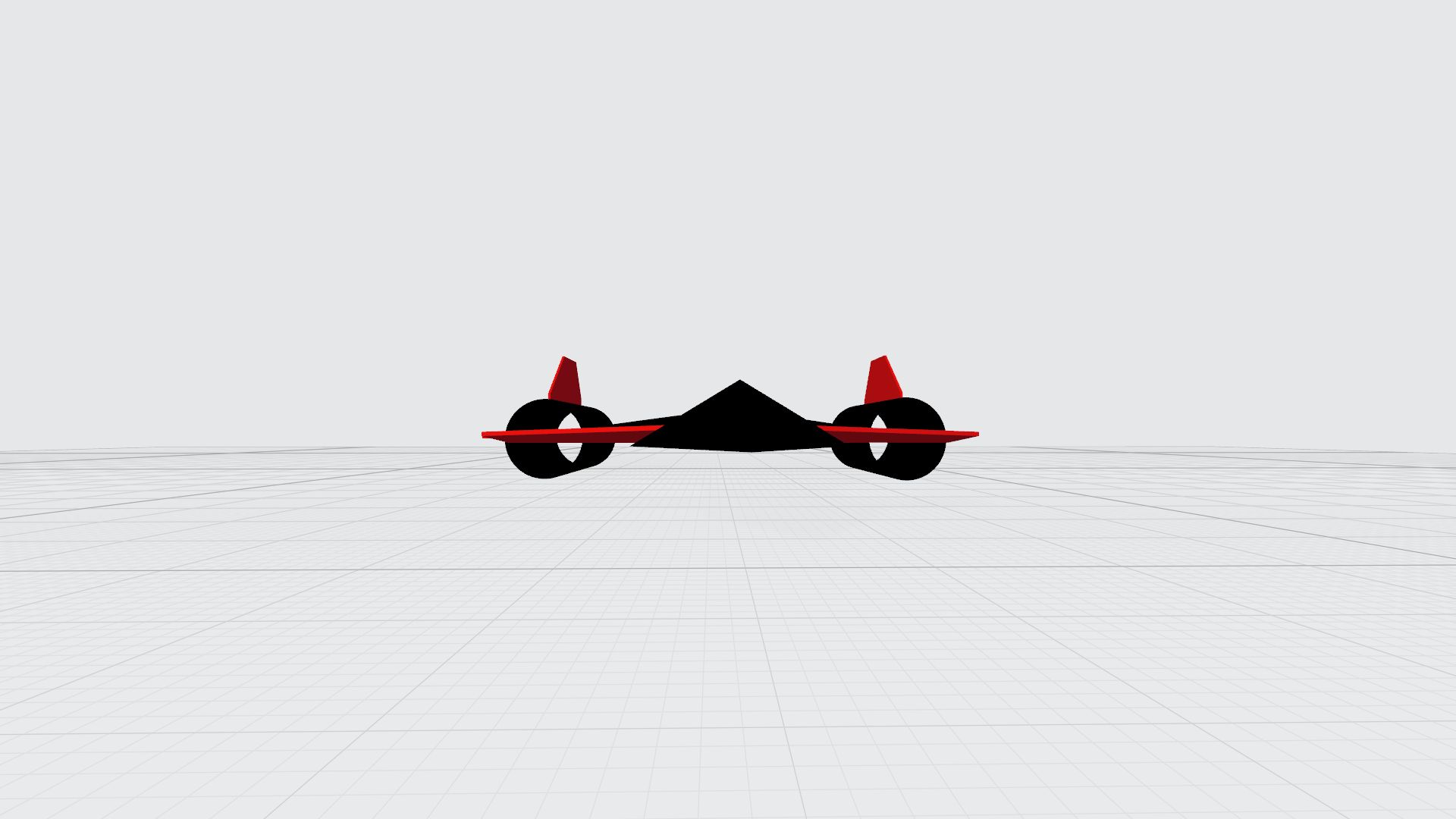
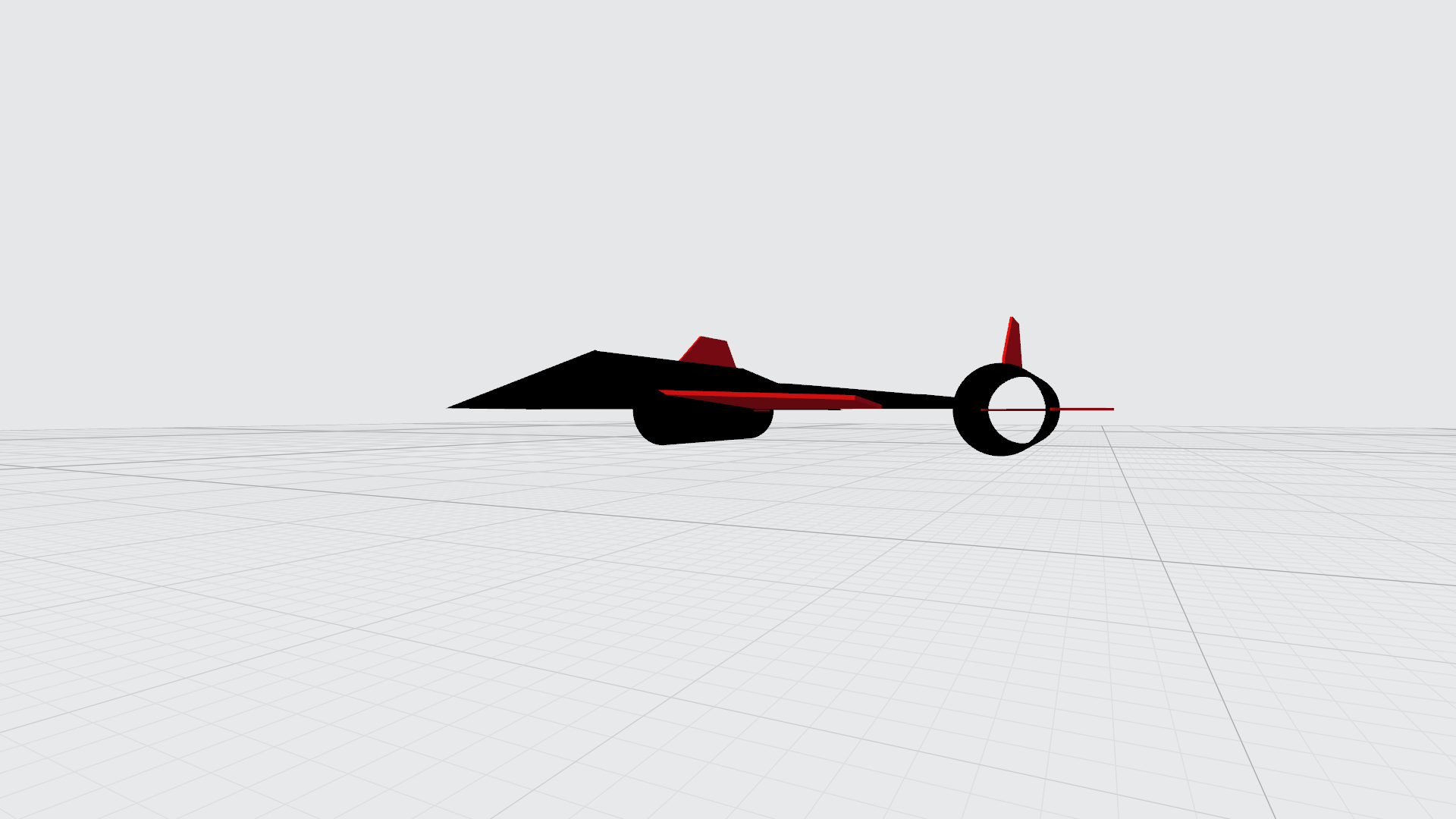
What I found so interesting about it, was it's Sr-71 Blackbird-esque design; And I was courious wether or not I could rebuild the thunderjet, with proper RC components this time. Now the original isn't available for a long time now, and it is faaar to small to fit modern hardware, so I used 3D Builder to sketch up a 3D model. In the pictures you can see below, the engine ducts on the sides are a bit reduced in size, since the were comically large on the original model, and brushless EDFs have a far greater power output than brushed Impellers. The Original also did not have Elevons, since it used thrust vectoring and had no elevator or rudder.
The full scale model (if I get around to building it) will use thrust vectoring for yaw aswell, since it cuts down on extra servos, which I'm going to use for something else.
So, if you look in the engine duct closely, you can see two red panels, which are control surfaces, which technically are elevons aswell, which are going to direct the airflow coming off the EDF, so you would have 3 axis thrust vectoring!
Let me know what you guys think, if it would fly, if the angle on the canards is to steep, which parts maybe best, or even if you have a 3D printer, and want to print it yourself, I would happily send you all the plans.
 

Attachments

  • ThunderJet1.png
    ThunderJet1.png
    367.1 KB · Views: 0
  • ThunderJet1_frog_view.png
    ThunderJet1_frog_view.png
    499 KB · Views: 0
  • ThunderJet1_side_view.png
    ThunderJet1_side_view.png
    415.9 KB · Views: 0
  • ThunderJet1_Three-q.png
    ThunderJet1_Three-q.png
    998.3 KB · Views: 0
  • ThunderJet1_Top_View.png
    ThunderJet1_Top_View.png
    572.4 KB · Views: 0

kilroy07

Legendary member
Pretty cool!
So, completely 3D printed?... I'll definitely be watching this thread!

Never heard of the jet, but I do love the SR!
 

Geniuslike

New member
Most likely it won't be 3D printed, because I don't have a 3D printer, and the material won't be strong enough and doesn't offer any flexibility in the design. The main body will be made out of foamboard most likely, with the bottom of the delta made from a stronger material than foamboard, most likely I'll use wood, since it will be the easiest for me to work with, same with the engine ducts, either PVC pipe, or wood, since I don't want the EDFs to just rip the jet in half.
 

kilroy07

Legendary member
Hummm.... 🤔
PVC pipe and wood.... might work for a display model, but I’m guessing way too heavy to fly.
I got lucky and found pringles cans fit my edf s just perfectly for my SR... might try that.
Edf s take a bit to spool up so you’ll want your build as light as possible.
 

Geniuslike

New member
I went looking for parts and for cost and ease I'll most likely take a 70mm EDF (the same model one from the Durafly Viper), using either two ~2.5Ah+ Lipo's or one ~6Ah Lipo, I don't know which setup is better, the dual battery setup might allow for more flexibility in the narrow fuselage.
And, if I get hold of one of my friends who has a Laser Cutter, I'll order a carbon fiber plate and use that as the bottom of the fuselage for rigidty.
The Pringles Can Idea is neat, and as far as I can tell they are the exact right diameter!
But I have a question, the Viper's takeoff weight is around 1kg with one EDF, does that mean taht I can safely go up to 2kg with my doual EDFs , or should I rather aim for 1.5kg and keep the battieries smaller?
 

kilroy07

Legendary member
But I have a question, the Viper's takeoff weight is around 1kg with one EDF, does that mean taht I can safely go up to 2kg with my doual EDFs , or should I rather aim for 1.5kg and keep the battieries smaller?
The stats are also taking in account wing area/loading, which will be completely different for your aircraft. There are some online calculators to help figure that fancy math stuff out... (I usually just wing it...) :LOL:
 

Vimana89

Legendary member
I think the design is nice. I saw a vid of the air hogs version called Jet Scream, same exact model. I tried to find one on eBay or Amazon but not many left. Why wood and carbon fiber and heavy, expensive materials? I think this plane would be just fine as a standard foamie. If you want it really big and powerful, keep the 70mm fans, but personally I'd scale the build down to 50mm fans, maybe 64mm max for a regular park flyer you could fly most places and transport easy.
 

L Edge

Master member
What size model is it going to be for the 70's and what is your calculated total weight? If you use PVC and wood, as kilroy07 said, you will be too heavy. Problem is, add weight to re-enforce structure so it doesn't fold, means bigger EDF and battery which means more weight and is groundhog day problem over and over.
Have you thrust gimbals for the 70's? Tough to find. You mention above the orginal did not have elevons or rudder, how will TV control the plane. Remember, if one engine goes out with TV, you lost it. How do you land if you don' have elevons?
 

Vimana89

Legendary member
An elevator and thrust differential will work but not optimally. As stated above, if you lose power you pretty much lose control. You might be able to land with one side and an elevator but it would be wonky. I would use smaller diameter fans, and a lighter build with better controls.
 

Geniuslike

New member
I think the design is nice. I saw a vid of the air hogs version called Jet Scream, same exact model. I tried to find one on eBay or Amazon but not many left. Why wood and carbon fiber and heavy, expensive materials? I think this plane would be just fine as a standard foamie. If you want it really big and powerful, keep the 70mm fans, but personally I'd scale the build down to 50mm fans, maybe 64mm max for a regular park flyer you could fly most places and transport easy.
The reason I intend to use the 70mm fans is simply cost and availability, the 70mm EDFs from the Viper have a good mounting system, are a good size for the pringles can approach, are cheap, and run on the 4S.
And I only intend to make the bottom plate of the hull from wood/carbon fiber, so I have a solid base, to mount the power system to.
 

Geniuslike

New member
What size model is it going to be for the 70's and what is your calculated total weight? If you use PVC and wood, as kilroy07 said, you will be too heavy. Problem is, add weight to re-enforce structure so it doesn't fold, means bigger EDF and battery which means more weight and is groundhog day problem over and over.
Have you thrust gimbals for the 70's? Tough to find. You mention above the orginal did not have elevons or rudder, how will TV control the plane. Remember, if one engine goes out with TV, you lost it. How do you land if you don' have elevons?
I used the Durafly Viper as a reference model, since I'll use the same EDFs (only two instead of one), which takeoff weight is 1050g, so I'll try to keep the maximum at below 2000g.
As for the thrust vectoring, I'll just use speeding up and slowing down one motor for yaw, and you are right, if one of them fails, the plane will go into a flatspin, since the thurst is located so from the cg. But that is a risk I'll just have to take. And I am going to use Elevons, the red portions at the back of the delta are going to be my elevons. If I am going to use the canards as elevons as well, I am not sure,
And I'll post my uptated, to scale design shortly
 

Geniuslike

New member
Update
Okay so, this model is now exactly to scale, the inner diameter of the ducts is excactly 70mm, the green cube you can see is 10x10x10 cm (or roughly 4") as a reference,
As you can see I made a neck of the plane a trapeziod instead of a wegde shape, at first mainly for looks, and making it easier to access the internals.
But I went deeper into the design of the power system, realized I further needed to adjust the design.
I extended the neck down the fuselage, as the wing itself didn't offer much space, and I didn't want to just strap the battery to the bottom (it's supposed to look cool and sleek after all!)
The Green and red rectangles you can see in the bottom view are these batteries to scale respectively.
ZIPPY Compact 5800mAh 4s 60c Lipo Pack
Rhino 3300mAh 4S 50C Lipo Pack w/XT60
As you can see they are to large to comfortably sit in the model (I'll probably go for the larger battery since it isn't that much bigger)
So I realized that have three choices now:
1.I'll either have to add a ridge to the bottom of the wing as well, to not have the battery stick out
OR
2.
I'll widen and thicken the "Neck" to allow the battery to fit
What do you guys think is the best option
OR
3.
Increase the size of the model so it will fit (but the 70mm will look smaller in relation)

What do you guys think is the best option?
 

Attachments

  • Capture3.JPG
    Capture3.JPG
    48.1 KB · Views: 0
  • Thunderjet.JPG
    Thunderjet.JPG
    68.3 KB · Views: 0
  • Thunderjet2.JPG
    Thunderjet2.JPG
    30.2 KB · Views: 0

Vimana89

Legendary member
I'll let somebody a little more experienced handle the dimensions. The rendering looks good, I like the way you shaped the fuselage. It will be pretty simple to build from(mostly) foam board and give good space and access for electronics. I just have no clue what your control setup will be like, not sure what those funky thrust vectoring flaps inside the tubes are, did the original little toy one have them? I'm no expert, but since they are fully enclosed in the tube, where will the thrust vector to but hitting the roof/floor of the tube and deflecting and losing power?
 

Geniuslike

New member
When I originally dreamt up the model it seemed like a cool idea, but it will probably be a pain to implement, so the surfaces will remain, but will be a extention from the bottom plate, and much closer to the Fan, to not place all the stress of the thrust on two screws that hold the EDF in place.
And earlier when I said thurst vectoring I actually meant using differential thrust for yaw, I somehow got that mixed up
As for the control setup
Two servos, two 70mm EDF's
Servos are for Elevons, Differntial thurst for yaw,
I may however use two more servos and use the canards as elevons aswell (see the Eurofighter Typhoon) since they are so far forward the force the produce will be very high and the plane will be more nimble.
And the canards will have no airfoil.
What I am unsure about is where to put the fulcrum on the canard, the Eurofighter seems to have it at the CoL of the canard (don't quote me on that, I'm just guessing since it is roughly in the first third) And weather to just glue the canard to the servo arm and make it direct drive, or put the canard on an axle and have the servo move said axle, added complexity but I don't know how putting all the stress on the servo mounting will affect it's longevity