Where to go; Foam Board Plan Details From My 3D Model

wi11ywonka

New member
Hello,

I'm trying to design my own P-51 out of foam board. I was going to use paper-craft designs which are made for flat printed paper. I, however, wish to design the skeleton, bulkheads, Retract housing and where all my electronics with go. I CAN do this in 3D with measuring everything out but it seems there is an easier way. Like this amazing gentleman, unrauv, whom has unfortunately passed away, but look at what he has done. So amazing and it seems as though the program knows about the thickness. Check this out:
https://forum.flitetest.com/index.p...constellation-plans-and-modeling.53454/page-3

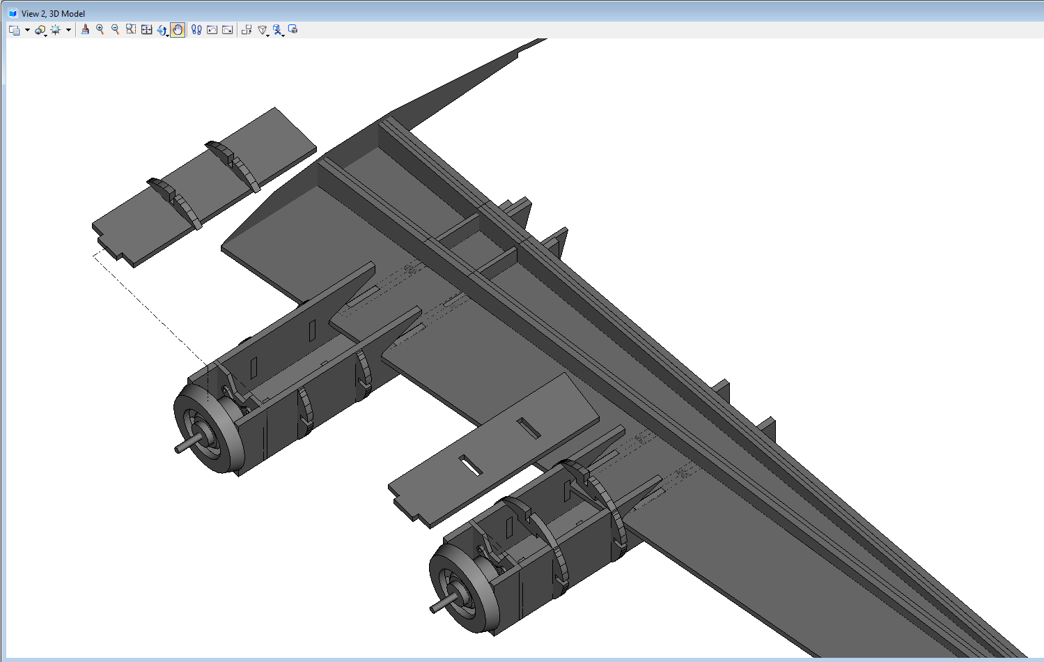
Here's an awesome picture of what he has done. Below is my 3D design. Is this Solidworks? Where can I go from here? Any suggestions would be great. I eventually want to print out plans on regular paper then remove one paper of the foam board and glue my prints directly on it, so I basically only cut once!
181766_933b623cfed6e1188d799f17007cc0bd.png

My_P51.jpg
 
Last edited:

FoamyDM

Building Fool-Flying Noob
Moderator
This is the dilemma I've had with 3D modeling in general. I know there is a way to make a cut list even a layout sheet where the computer takes the parts and optimized the cut layout. but it is Well beyond me. anybody know where we should look. I would much prefer to do this all in 3D cadd.
 

wi11ywonka

New member
This is the dilemma I've had with 3D modeling in general. I know there is a way to make a cut list even a layout sheet where the computer takes the parts and optimized the cut layout. but it is Well beyond me. anybody know where we should look. I would much prefer to do this all in 3D cadd.

I here ya, but I went to school for 3D animation so Its no problem for me... just a bit tedious to model everything from scratch. The Gentleman, unrauv, who passed away, seemed to have the program do a lot of automation for him, based on what I saw, I could be totally wrong. But I'm impatient so I decided to go the scratch way. I just scaled it down to real world size to what I wanted. Then I started modeling things like the power pod the motor for power pack C as references so I can build the guts accordingly then am going to account for the 1/4 in thickness of the board. I saw unrauv made the skeleton out of FB and just used poster board for the skin. This seems easier to deal with but After I do that I want to make the entire thing out of FB cuz its more sturdy. I will show WIPs when I get home. Thanks for the response!
 

wi11ywonka

New member
This is the dilemma I've had with 3D modeling in general. I know there is a way to make a cut list even a layout sheet where the computer takes the parts and optimized the cut layout. but it is Well beyond me. anybody know where we should look. I would much prefer to do this all in 3D cadd.

I like your Crimson Skies Dragster! How do you go about with your process of design? Illustrator, Photoshop? How do you end up with such nice clean plans?
 

FoamyDM

Building Fool-Flying Noob
Moderator
I use AutoCAD Lt 2012.
My current design method. (mostly because Sketchup's flatten add-on feature didn't work for a while for me.)
  • I import the images... scale it so the fuse matches just larger than standard pod (2" for B or C, 1.25" for A) or match Prop sizes
  • I draw over the image. P(oly)line mostly, Measure arc to confirm bent edges and flat lines should match up
  • Then I offset, shift change the Linetypes/layers as appropriate (sometimes I do it right and put it in correctly first.) to account for the folds and think about where I want bend, tapers, or slight bends (like on the FT wing tops). Where ever the Top and bottom layers are a flat solid piece in my mind.
    • Lt Blue Scores are for slight bends, like in the tail tapers, or paper removal edges.
    • Red line grooves are for bigger more defined bends, or the edge of foam removal.
    • Dots/Crosses/Concrete is for paper removal.
    • Long Hatched lines are for long ironed or sanded tapers
    • Short Hatched lines are bevels.
    • DON'T FORGET to MARK CG's a hole. You can always dot with glue if it's right.
  • When I'm happy, I try to make the outlines a single piece to facilitate moving it.
  • Then I arrange it to be in the inner black box. (The size of a Adams ready board 29.5" x 20"). this is set in the standard FT sheet.
The end product allows me to take the prints and mount directly to DTFB and cut.

Estimating model Weight. Knowing how many sheets is critical. Each sheet is 115g. on a typical layout approx. 75-65% of it is used. I go conservative at 75%, so ~85g/sheet Then I assume 1 Stick of glue 2 sheets. so that adds back ~24g. then you can look up the weights of the electronics, and Battery. A-Pack = ~100-130g, C-Pack = 300-350g.
 

wi11ywonka

New member
I use AutoCAD Lt 2012.
My current design method. (mostly because Sketchup's flatten add-on feature didn't work for a while for me.)
  • I import the images... scale it so the fuse matches just larger than standard pod (2" for B or C, 1.25" for A) or match Prop sizes
  • I draw over the image. P(oly)line mostly, Measure arc to confirm bent edges and flat lines should match up
  • Then I offset, shift change the Linetypes/layers as appropriate (sometimes I do it right and put it in correctly first.) to account for the folds and think about where I want bend, tapers, or slight bends (like on the FT wing tops). Where ever the Top and bottom layers are a flat solid piece in my mind.
    • Lt Blue Scores are for slight bends, like in the tail tapers, or paper removal edges.
    • Red line grooves are for bigger more defined bends, or the edge of foam removal.
    • Dots/Crosses/Concrete is for paper removal.
    • Long Hatched lines are for long ironed or sanded tapers
    • Short Hatched lines are bevels.
    • DON'T FORGET to MARK CG's a hole. You can always dot with glue if it's right.
  • When I'm happy, I try to make the outlines a single piece to facilitate moving it.
  • Then I arrange it to be in the inner black box. (The size of a Adams ready board 29.5" x 20"). this is set in the standard FT sheet.
The end product allows me to take the prints and mount directly to DTFB and cut.

Estimating model Weight. Knowing how many sheets is critical. Each sheet is 115g. on a typical layout approx. 75-65% of it is used. I go conservative at 75%, so ~85g/sheet Then I assume 1 Stick of glue 2 sheets. so that adds back ~24g. then you can look up the weights of the electronics, and Battery. A-Pack = ~100-130g, C-Pack = 300-350g.

Wow! That's pretty neat process. Seems that with our methods you have to do alot of thinking before hand, but this whole process is fun. Thanks for sharing!
 

wi11ywonka

New member
FoamyDM,

On a side(noob) note, where in the account settings did you change under your name where it says
"Building Fool-Flying Noob"

On mine it just says "new member".
 

FoamyDM

Building Fool-Flying Noob
Moderator
AutoCAD allows you to shift things VERY easily, and be very exact, and it makes scaling simple. I will be trying to do a "How I make a RC plane Plan" video. Actually it is the reason I have to make another entry into the FTFC20 CtM challenge.
 

FoamyDM

Building Fool-Flying Noob
Moderator
FoamyDM,

On a side(noob) note, where in the account settings did you change under your name where it says
"Building Fool-Flying Noob"

On mine it just says "new member".
I think it is now a vestige from the prior format...I can't seem to find how to change it.
 

FoamyDM

Building Fool-Flying Noob
Moderator
@wi11ywonka - I didn't say this, I don't believe, and I should have - Those models look great!
Keep up the good work. and when you find an easy way to rearrange and flatten the parts into a printable sheet. I will heading that way.
 

wi11ywonka

New member
@wi11ywonka - I didn't say this, I don't believe, and I should have - Those models look great!
Keep up the good work. and when you find an easy way to rearrange and flatten the parts into a printable sheet. I will heading that way.

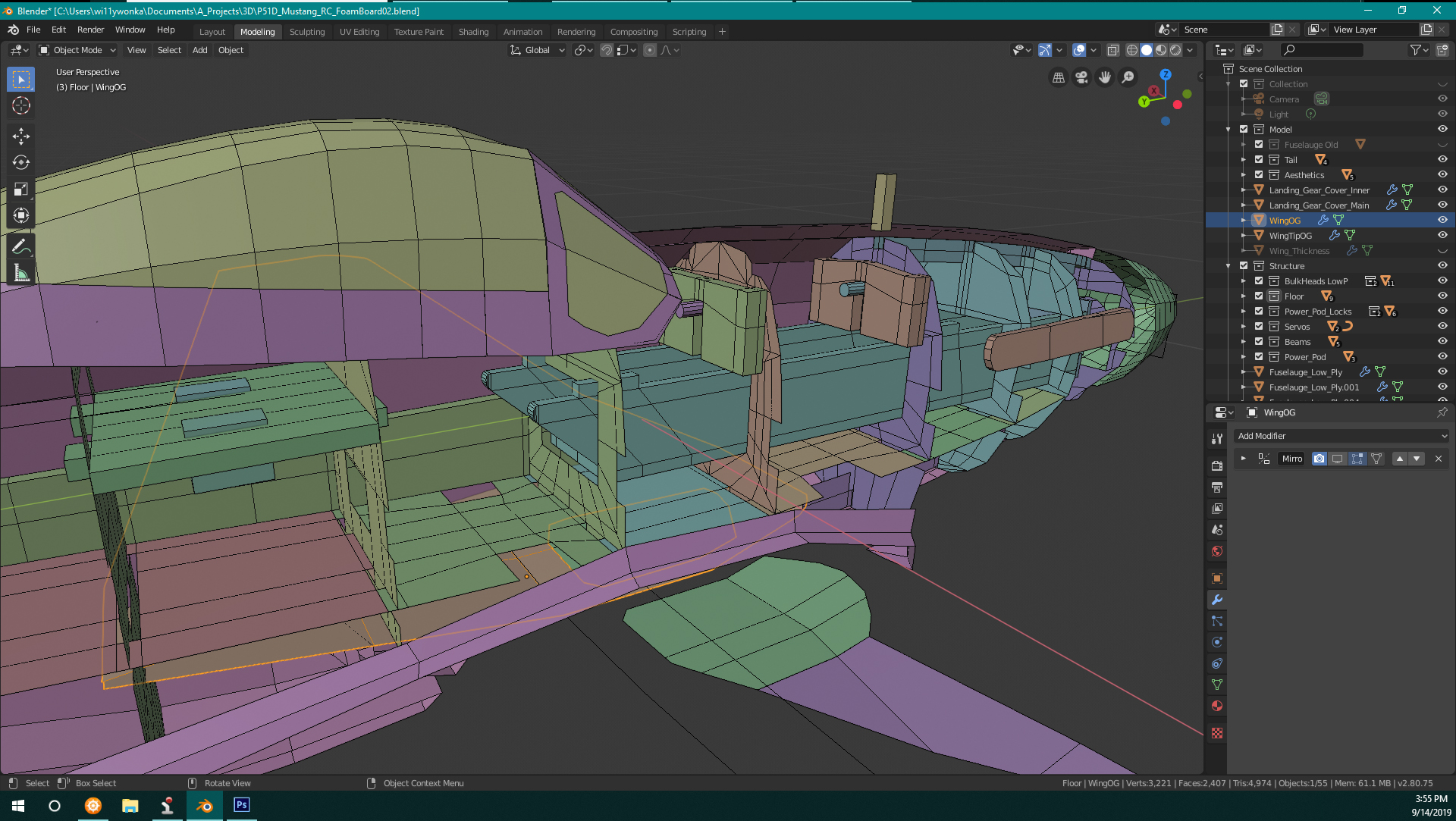
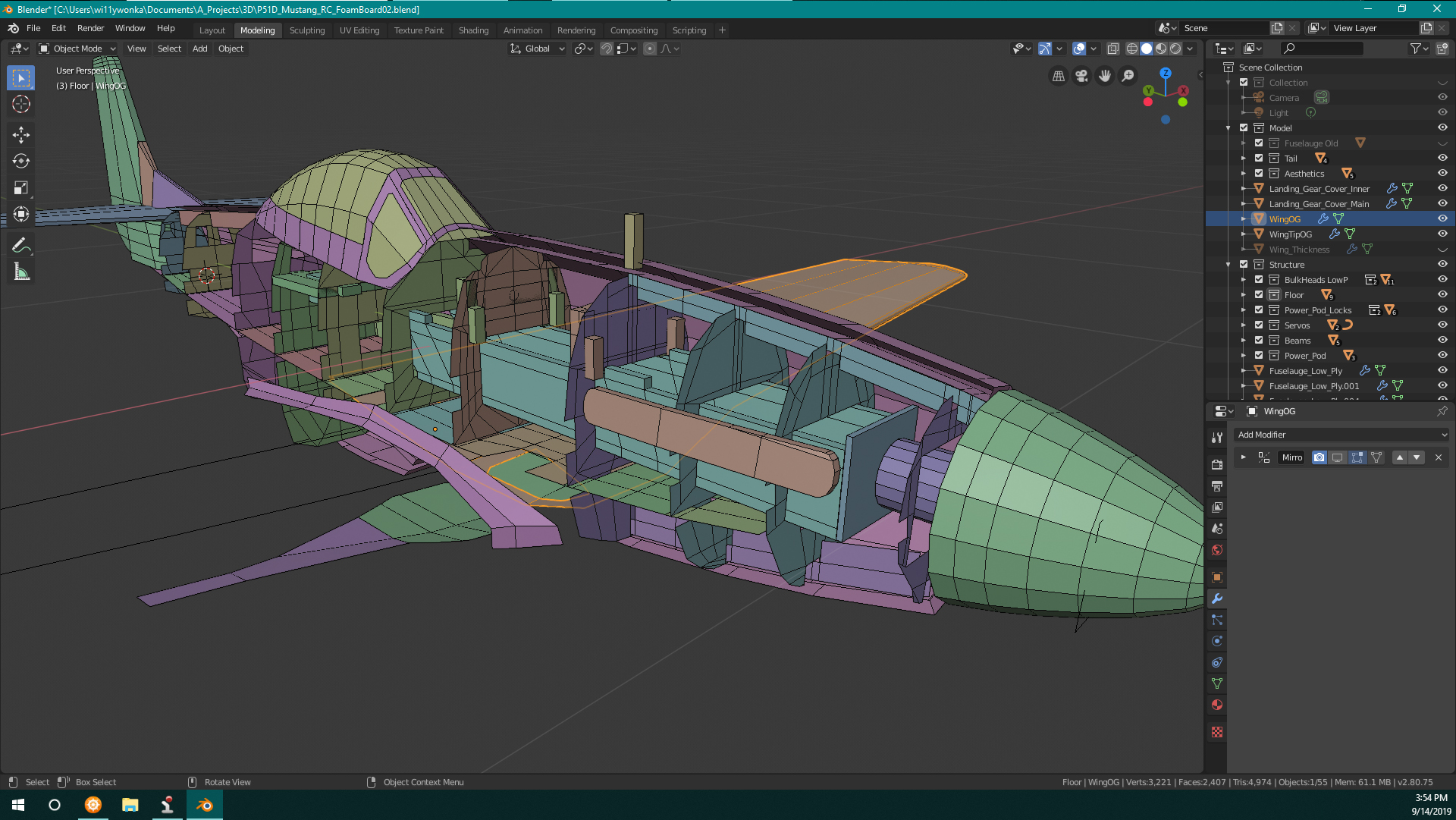
Here's what I've done so far. Apparently there is an included addon to Blender that exports an unfolded model complete with tabs and numbers based on the UVs, and cuts... basically I can tell it HOW to cut and fold!
Mustang02.jpg
Mustang03.jpg
Mustang04.jpg