Winter Build 2018/19: Hangar 9 P-47D Razorback

willsonman

Builder Extraordinare
Mentor
No pictures today. I took time last night to make progress in a couple of minor places. I have a few e-tract units in my stash and started rummaging through them to find something that would work for the tail gear. I found a suitable one but the endpoints were funny and not consistent per my servo tester. So I swapped out the motor and control board form a good unit of the same size to the case and setup that I knew would work.

I also looked through my stash of offset hinges to figure out how the landing light would work. I think I have an easy solution for that so I drew up the reflector in Fusion to print later. I also dug around and found a micro switch that will cut off the light when retracted.

Need to finish up the OCWG situation. The other one needs to be assembled, the can paint needs removed, and the prints themselves need to be smoothed out before I can install them into the airplane. Once that is done, I'll move onto the intercooler doors on the sides of the fuselage.
 

willsonman

Builder Extraordinare
Mentor
Coming back from FFTX left me a bit drained but I took some time to address a few things.

I picked up some acetone to remove the paint from the oil cooler door. No good. I resorted to sanding it off and the bend ripped on one side. Lesson learned. The paint needs to be removed first. I'll prep some remaining aluminum properly before I cut out new doors. I did manage to get one print smoothed for this. I applied acetone with a cotton swap and let it dry out.

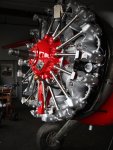
The prints for the dummy radial are a design from Damon Atwood. It is an earlier version of a 9-cylinder R-985 radial that he posted to Thingiverse before he removed it from there to start his own business at atwoodaviation.net. He has exceptional models but there are a few issues with this earlier version. The print for the crank case is fairly narrow and needs to be honed out to accept the outrunner with appropriate clearance. Further still, the front portion does not allow for the engine to be situated further back. The P-47's engine was a R-2800-59B that utilized a constant speed, variable pitch propeller. The dome on the crank case is elongated on the R-2800 to accommodate the hydraulics for this. The R-985 does not have this intended use. I drew up a dome to accommodate the radial sitting back further and it may yet need some refinement but it's getting to be the look I'm after.
IMG_7371.JPG

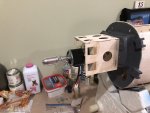
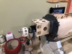
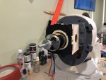
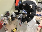
Here is the start of the whole setup. I epoxied the motor box per the instructions and mounted the motor. Using the crank case I can see that I can remove some of the wood from the box to mount the radial when I figure out the final placement.
IMG_7372.JPG IMG_7363.JPG

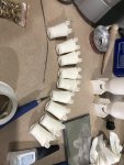
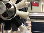
The cylinders have all been printed, assembled and finish work done. I need to do a little acetone work to smooth them out but I do not plan to go too crazy here.
IMG_7373.JPG

The other reason I started on this area is that I received a Sense Innovations ESS-AIR sound system. I've never played with these systems before but I've always wanted to. I've felt that they lack a lot of tonal depth and having dabbled in acoustics in the past I thought I would have a go. The main problem is that these are not like conventional speakers. They rely on the sympathetic vibration of the medium they are mounted to. The acoustic volume seems to be irrelevant. I tried it on the balsa fuselage and it was a thin and tinny sound that lacked the typical depth. I placed the driver on a bare piece of 1/2" pink foam and it was much better. Then on a sheet of FT foam board... it was AMAZING. Loud and tonal. Therefore it really is about surface area. I then tried a sealed box and the sound was OK, but muffled. The plan now is to try and construct a foam box that will go INSIDE the motor mount box that will vent through the holes in the top with the drivers affixed to the bottom. The foam will project the sound and the open holes will provide the projection. I'll likely need to play with this in terms of size and all but I think I have a good amount of area beneath the cowl to elongate the box if needed. I plan to do a video on this as I make progress on this front and come up with a final solution. There is not a lot out there to really look at optimal tuning of these sound systems.
 

willsonman

Builder Extraordinare
Mentor
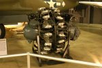
To further underscore the engine dome, I am attaching reference images.
R-2800:
Pratt_&_Whitney_R-2800-21_USAF.jpg

R-985:
Pratt_&_Whitney_R-985.jpg

And from this view you can see how far the first cylinder row is situated from the front of the cowl.
Image-30.jpg
 

willsonman

Builder Extraordinare
Mentor
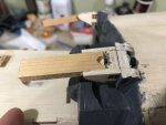
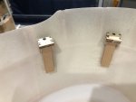
In order to work on the complete rhinoplasty that is required on this one, I had to get things positioned right. To start, I had to mount the cowl. Knowing I intend to make functional cowl flaps, I trimmed off a portion of the mounts as close as I dared. The mounts on the fuselage and the ones that get glued onto the cowl were both trimmed with my razor saw. I then inserted 2" strips of hard wood that would glue into the mounts and provide additional area to secure to the cowl. I had to remove a bit of wood to make clearance for the bolt that holds the mount in place.
IMG_7374.JPG IMG_7375.JPG

I sanded the glass on the interior of the cowl first for better adhesion. With the cowl in place, I dripped thin CA from the inside of the cowl with the fuselage on its tail. I did each one individually, checking position before I applied glue. I held pressure on the wood parts for over a minute each to make sure the bond was good. After removing the bolts, I was able to apply epoxy all around the mounts inside the cowl.
IMG_7376.JPG IMG_7377.JPG

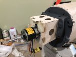
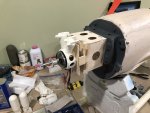
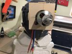
I needed to trim up the motor box a bit more to recess the dummy radial further back. The tabs protrude 1cm from the motor mounting plate. I then made a mounting plate for the dummy radial. Simple thin ply with ply plates that go around the motor box. Screws will affix the plate to the box. I had to also cut a relief for the motor wires.
IMG_7381.JPG IMG_7380.JPG IMG_7379.JPG IMG_7378.JPG IMG_7382.JPG

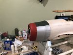
With all this work done, I can now focus on completing the dummy radial mounting position. I think I need to trim the tabs on the box a few more mm to clear the radial rod tubes. Then, I can finalize the nose of the crank case. With the dummy complete I can then design and complete the chin scoop design and print it as well. I can also move onto the sound system box.
 

jaredstrees

Well-known member
Wow. The level of detail you obtain is amazing. I'm still happy when the tape goes on straight or my covering isn't wrinkled!
 

willsonman

Builder Extraordinare
Mentor
Thank you! I've come a long way in the details department over the years. I always attribute this to experience and never being wary of trying something new. At the end of this build, I suspect this will be something very special.
 

wilmracer

I build things that fly (sometimes)
Mentor
Stellar work here. The changes you've made to the radial look great and I love that you're going to the effort to get it positioned correctly. The factory look is fine for an ARF but that engine is WAY to far forward to look scale. I'm very interested to hear the sound box solution you come up with. I know you've got a good ear for these things and it will be really cool to hear her sounding "scale" too :)

Keep up the great work!
 

willsonman

Builder Extraordinare
Mentor
My only complain on the factory mounting situation is of two notes. 1: It is HARD to do. 2: I had TWO of the ply mounts break a bit. This does not bode well for the use of a gas engine. While the intention is to use the cowl in a fixed position, I'm fairly certain that screws through the cowl would not be a complaint by many. Still, it's worth the effort to go through for a cleaner look IMO.

Yes, when it comes to sound, I am picky. It comes from my music degree and years of classical training. Usually, on these smaller setups, you lack the deeper tones. This is just physics. It takes more air to produce lower tones. I should know this as a low brass player. A LOT of air is used on the low end to fill the void. As these seem to operate better off of surface area to produce the tones, I think the best way is to try and maximize the sympathetic vibrational surface area. Hopefully, the solution I find will be satisfactory.
 

PsyBorg

Wake up! Time to fly!
I wonder....
When we changed our sub bins from a pressure box to a folded horn configuration the power and dynamics changed drastically.

I wonder if that might help you out a bit. Use hardwoods for the reflectictive side and lighter woods for sides to tune the resonance.

Or if you have the room go for a wave guide tube like they do in them Bose radios.
 

willsonman

Builder Extraordinare
Mentor
Yeah, I had thought about transmission line enclosure design but again, our typical speakers operate based on creation of pressure waves. The traditional designs optimize and tune for these waves of pressure. Since we are not creating ANY pressure waves we need to think more in line with something akin to the piano. There is a single board that vibrates sympathetically with all the strings as the vibrations are transmitted to the board through the bridge. This is very different than say a wind instrument like a tuba. In a tuba, the lips vibrate using air and each time the pips open and come back together it creates a volume of air in the form of a pressure wave. This wave then predicts the pitch based on the length of tubing and volume of that tube. So, more air and larger diameter makes lower tones... much akin to our traditional loudspeakers. Whereas with string instruments have larger surface areas and the volume, in a cello for example, dictates more of the tone.

A good example of this sympathetic idea is like comparing different sizes of piani. An upright or spinet piano will never be as LOUD to fill a concert hall, let alone accompany and entire orchestra. Therefore, an increase in sound board surface area is incorporated. therein you have the different SIZES of piani for different venues. You would never use a 9-foot concert grand in a chamber ensemble performance with even 3-5 other instrumentalists. A 5 or 6- foot grand would be more suitable, which is why these grands are more preferred in a home setting for professional musicians. The increase in surface area dictates the loudness but the materials, more or less, dictate the tonal qualities.

The tonal aspects I'm dealing with have a lot to do with the energy inputs. A concert grand piano will have nearly 10 TONS of tension from all of the strings. That is a LOT of potential energy that can be transferred and therefore you need a more rigid structure of appropriate density to transfer that energy without distorting. These systems are using a very modest mount of energy in the neighborhood of 40-50 watts. Therefore, the material needs to be softer for efficient energy transfer and manipulation of that material for tonal quality is the head-scratcher.

I'm not trying to justify myself but I do have a music degree, worked as a piano repair technician's assistant for 2.5 years (rebuilt 6 grand piani), spent my teenage years on the road a lot and during that time extensively researched acoustics to apply to my car audio system. I've done a lot around this subject but these transducers have me at the lower end of the learning curve.
 

willsonman

Builder Extraordinare
Mentor
LOL, well there is something to be said for conceptual understand and practical application. One thing at a time.

Ran some numbers. Lets put things on an even playing field. 1W of power = 1N m/s. My sound system for this project maxes out at 15W. This translates to roughly 11 ft/lbs of force. Comparing a piano at 10 tons equates to ~98067 watts! So, obviously we are not even on the same dimension of power use here, thus why resonance of wood is completely impractical.
 

PsyBorg

Wake up! Time to fly!
Heh.. thats what I get for posting in the middle of the night.

Thought that was a speaker driven system not tranducers. Should probabably start puttin on the glasses before posting or start waiting til morning after the eyes focus.
 

willsonman

Builder Extraordinare
Mentor
No, you're all good. THis is a good discussion to have since it is very atypical from what people generally know about sound reproduction.
 

AkimboGlueGuns

Biplane Guy
Mentor
Yeah, I had thought about transmission line enclosure design but again, our typical speakers operate based on creation of pressure waves. The traditional designs optimize and tune for these waves of pressure. Since we are not creating ANY pressure waves we need to think more in line with something akin to the piano. There is a single board that vibrates sympathetically with all the strings as the vibrations are transmitted to the board through the bridge. This is very different than say a wind instrument like a tuba. In a tuba, the lips vibrate using air and each time the pips open and come back together it creates a volume of air in the form of a pressure wave. This wave then predicts the pitch based on the length of tubing and volume of that tube. So, more air and larger diameter makes lower tones... much akin to our traditional loudspeakers. Whereas with string instruments have larger surface areas and the volume, in a cello for example, dictates more of the tone.

A good example of this sympathetic idea is like comparing different sizes of piani. An upright or spinet piano will never be as LOUD to fill a concert hall, let alone accompany and entire orchestra. Therefore, an increase in sound board surface area is incorporated. therein you have the different SIZES of piani for different venues. You would never use a 9-foot concert grand in a chamber ensemble performance with even 3-5 other instrumentalists. A 5 or 6- foot grand would be more suitable, which is why these grands are more preferred in a home setting for professional musicians. The increase in surface area dictates the loudness but the materials, more or less, dictate the tonal qualities.

The tonal aspects I'm dealing with have a lot to do with the energy inputs. A concert grand piano will have nearly 10 TONS of tension from all of the strings. That is a LOT of potential energy that can be transferred and therefore you need a more rigid structure of appropriate density to transfer that energy without distorting. These systems are using a very modest mount of energy in the neighborhood of 40-50 watts. Therefore, the material needs to be softer for efficient energy transfer and manipulation of that material for tonal quality is the head-scratcher.

I'm not trying to justify myself but I do have a music degree, worked as a piano repair technician's assistant for 2.5 years (rebuilt 6 grand piani), spent my teenage years on the road a lot and during that time extensively researched acoustics to apply to my car audio system. I've done a lot around this subject but these transducers have me at the lower end of the learning curve.
I guess I'll stick to my guitars. :p
 

willsonman

Builder Extraordinare
Mentor
Over the holiday I was able to make some progress and I'll cover this step by step.

I completed the mounting plate for the dummy radial. I positioned the dummy over it and realized I needed to trim the corners down to not bump into the cylinders. I painted it black but I did not paint where the dummy mounts. I had to paint the dummy radial, fully assembled, prior to mounting so that I could get the paint brushed between the cooling fins.
IMG_7383.JPG IMG_7391.JPG IMG_7392.JPG IMG_7393.JPG

With the painting mostly done, I glued on the dummy and painted the remainder of the plate. You can see in the attached picture how it shows and needed to be painted after affixing the dummy.
IMG_7424.JPG

I also measured the distance that needed to be covered by the dome of the dummy and adjusted my model in Fusion. The print took an hour and came out perfect the first try. A bit of sanding and acetone treatment and CA glued it in place.
IMG_7426.JPG
 

willsonman

Builder Extraordinare
Mentor
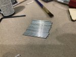
I picked up some aluminum tube at the LHS and used my polishing compound to shine it up a lot. You can see the before and after comparison in the attached image. I cut the tube using a razor knife rolling the tube while applying pressure. A few rolls and the cut is done cleanly.
IMG_7425.JPG IMG_7427.JPG

I marked where the holes needed to be in the dome and drilled them with an appropriately sized bit. The tubes slipped into the dome and then up into the head. The look is really starting to come together. While there is some additional detail to come, I'm on the right track here to make the front end of the airplane a focal point rather than the afterthought of the provided dummy.
IMG_7431.JPG

I also got the landing light reflector printed and treated with acetone. I applied some of my aluminum tape and polished it with a rag. It turned out quite well and I applied a clear covering from overhead projector plastic I had on hand. Glue was Formula 560 canopy glue.
IMG_7432.JPG IMG_7433.JPG
 

willsonman

Builder Extraordinare
Mentor
Finally, I had some time to play around with a sound system for the airplane. I've experimented with a few materials and designs but I want to cover a final solution and how I got there in another video. To type it all out would be a novel. I put together a video to have you all give a listen and provide me some feedback. It is merely a subjective listen and I did my best to record better audio for the samples. Have a listen and feel free to shoot me your opinions.


PsyBorg

Wake up! Time to fly!
I think the pink foam had the better sound in behind the motor mount for the motor for me in headphones.

The white foam had slightly better tone but alot of the sound was lost and not as clear specially after the start up sequence finished and transitioned into the motor running.

In both cases the gun did not sound like any gun I have been around or ever heard. It sounded more like the motor sound but with a hole in the exhaust.

The final part of the gun rang like a 3030 in the woods on a cold crisp morning.

I would play with using heavier more dense foam on the transducer side and deeper box if you can with the thinner foam or maybe even light cardboard to absorb a bit of the higher pitch range and maybe get a beefier low end.