Winter Build 2018/19: Hangar 9 P-47D Razorback

willsonman

Builder Extraordinare
Mentor
Ok, so weekend progress was slow... mostly due to recovery from my ankle still.

I forgot that I wanted to add functional drop pylons. I started by installing a pylon onto the wing using the intended two screws and tracing the placement. I then removed the pylon and removed the balsa sheeting to remove the blind nuts to save a bit of weight as well as allow a servo wire to pass through into the wing. I left other structures in place as they may add strength and were not worth additional effort.
IMG_7671.JPG IMG_7672.JPG IMG_7677.JPG

The pylons needed to be gutted so I used some needle nose pliars to carefully remove the wood bits. From there I needed to fill holes using epoxy. Make sure to scuff up the area before so the epoxy has something to grab onto. Just using 5-minute stuff here. No need for anything else since its just for filler.
IMG_7669.JPG IMG_7670.JPG

I eyeballed (TLAR) the location of where my drop tanks would go and positioned one of my release mechanisms where it needed to go. Carefully cut through the plastic with a #11 blade and the printed mechanism popped right in. Secure with CA. For those not familiar with my design you can pick it up on Thingiverse here:
https://www.thingiverse.com/thing:2811104
IMG_7673.JPG IMG_7674.JPG IMG_7675.JPG IMG_7676.JPG

I started looking at my lights and I am thinking I may stray from the true scale here again as I'm trying as much as possible to work with the parts supplied in the kit. The spirit of this build, after all, is to make this a Builder's ARF (B-ARF). More on that in a bit.
 

willsonman

Builder Extraordinare
Mentor
I will create a recess into the balsa skin for the plastic to sit. I'll use Medium CA to place it there and then blend the seam with spackle... much like I did with other plastic parts I've done already.
 

willsonman

Builder Extraordinare
Mentor
Yes, but there are sacrifices that have to be made at times. Given the very limited travel the servos will have to do to perform the drop, I'm not too worried. I used 5g servos in the Corsair and they work just fine... If those ever go, I'll never drop anything ever again. They are BURIED inside the wing.

Update coming. Just bare with me. My schedule is a little off today due to a number of unrelated and boring factors.
 

willsonman

Builder Extraordinare
Mentor
OK, so first off, I wanted to stick with as much of the ARF as originally planned as possible. The wing tip lights are a bit off scale but as this MODEL is intended to be be a scale down version of an airshow subject... The navigation lights would be brought up to modern requirements. This means navigation AND strobe lights. I cut the pieces out and trimmed/sanded to fit. They each have a L and R to indicate the correct side so it is hard to screw up. I cut off the colored plastic and put on a sheet of styrene using medium CA. Drill out two holes and blend the styrene into the form. I covered them with aluminum and added some rivets because... I'm me. The covers still need to be installed but this was the hard part of it.
IMG_7680.JPG IMG_7678.JPG IMG_7684.JPG

Moving on. I added servos to the drop pylons. I used my dremel to make a recess into the balsa. Medium CA holds the pylon in place and I just need to add some spackle to blend it.
IMG_7681.JPG IMG_7683.JPG IMG_7682.JPG IMG_7685.JPG

I started working on the landing light but did not get far as my ankle started to hurt. More later.
 

Mid7night

Jetman
Mentor
Oh COOOME OOON....are you KIDDING ME?!? Fastener markings INSIDE the light housings?!?!

You're too much dude, too much..... AND WE LOVE IT. XD
 

willsonman

Builder Extraordinare
Mentor
Well, to be honest the rivet details are what I really enjoy. This model makes it easy. No soldering iron needed. I'm using a more scale diameter for the rivets at 0.9mm with an orifice of 0.7mm. It's not perfectly sized but it's closer than the Corsair's rivets. From about 3 feet away they look like pin pricks but getting closer you question yourself... then at 1 foot you can see the details more. It's gonna be a fun trick. Time consuming, but fun.
 

willsonman

Builder Extraordinare
Mentor
The covers for the wing tip lights are NOT symmetrical. The top side of the wing is more curved so make sure you note this and apply the half of the moulded plastic that is applicable. I carefully cut things as square as possible with small scissors and sanded the edges straight. I then placed the lens and traced it, cut away a recess in the wood, and glued the lens using Formula 560 Canopy glue. It takes a full day at least to fully dry. I did not want to use CA and risk the clear part fogging out from the CA. I've removed the tape that held it in place and sanded the edge to blend it but forgot the snap a picture.
IMG_7686.JPG IMG_7687.JPG

This is why I forgot... I moved onto the landing light. I looked in my stash of offset hinges and there was nothing that would work geometrically. Thingiverse to the rescue!
https://www.thingiverse.com/thing:2162643
This hinge worked well with a touch of modification with some hardwood. Note that the opening for the light is slightly off from my scale location. This is due to the wing spar... I did not want to cut into that at all. There is an additional box structure that interfered a bit but its minor structure and I did have to cut into it a little. With the limited space I ended up with a smaller hole too which made the light rotation more difficult. In the end, a few hours of working the problem paid off. A 5g servo does the job and the linkage is set to have 100% travel. This means I can directly link it to the retract channel. I have a little PCB coming from pololu that will also control the light being on or off when deployed. I had planned on using a physical micro switch but it was getting cramped inside this area. A 6$ PCB was worth it and probably lighter.
IMG_7691.JPG IMG_7692.JPG IMG_7693.JPG

In the end, I mounted the servo forward of the lens. There is ply and balsa on the skin for this area so I'm not too worried about it. If it fails, I can service it pretty easily. I've got video of it working that I'll include in my next update video.
IMG_7695.JPG
 

willsonman

Builder Extraordinare
Mentor
I took time last night to complete the other wingtip light cover. I snapped a picture of the completed tip as well as the other tip with the little bit of wood cut away. I spent a lot of time then routing all the wires I've installed so far. The left wing now has wingtip light wires, landing light wires, landing light servo, and pylon servo. I've not installed anything that I am supposed to yet and I am being inundated with wires!
IMG_7698.JPG IMG_7699.JPG

I also swapped out my 0.4mm nozzle in my printer for a 0.2mm nozzle. It's time to try and print the Instrument panel I designed quite a while back now. I say try in jest... it actually turned out quite well. Well enough I think I will use it. I've included a side-by-side with the original panel so you can see how truly out of scale it is. I do love how the little screw heads showed up too. It may have taken around 8 hours to print on that tiny nozzle but its worth it.
IMG_7701.JPG IMG_7700.JPG
 

willsonman

Builder Extraordinare
Mentor
With all these wires and extra bits in the fuselage, we should go through the exercise of adding up the number of channels I'll need. So, lets add up all the stuff and then do a break down of channels.

Throttle
Aileron (on Y as intended)
Elevator
Rudder
Flaps
Retracts(Main)
Retracts(tail)
Main Gear Doors
Pylon drop (tanks or bombs)
Landing light movement
Landing light on/off
Navigation lights on/off
Intercooler doors
Oil cooler door/ Wastegate valves
Cowl flaps
Machine gun sound (did you forget about the sound system?)
Engine sound

Ok, so that is 17 items... already one past my default 16 channels but no biggie. First lets Isolate everything that will tie into the throttle channel.

Throttle
Cowl Flaps
Intercooler doors
Oil cooler door/ Wastegate valves
Engine sound

All of this can be isolated to at least 2 channels. It really depends on how all the servos are reversed and whatnot. If I can get away with one channel great but still, 5 items down to two channels is great. Lets move onto the gear...

Retracts(Main)
Retracts(tail)
Main Gear Doors
Landing light movement
Landing light on/off

Again, I can knock this down from 5 to two channels. I say two because the inner gear doors will need their own channel to operate before and after the mains retract. So, the reversing may require a third channel but its not likely if I plan ahead accordingly.

After the condensing of things that leaves us with a minimum of 10 channels and a maximum of 12. I've got a few spares so if I need to refine some movement of parts I am free to break that part out. I try to set things up mechanically to not need to do this but it does happen.
 

willsonman

Builder Extraordinare
Mentor
I had a crash course in this on my Corsair build. I ended up using all 16 channels for that one. TBH though, if I did an animated cockpit on this, I would be using all 16 channels again.
 

wilmracer

I build things that fly (sometimes)
Mentor
That .2mm nozzle has great results. Definitely worth the extra print time :)

That is definitely a lot of channels to manage too. I know you'll get it figured out :)
 

willsonman

Builder Extraordinare
Mentor
OK, so the light circuits came in on Friday and they have been oddly time consuming. For reference, I purchased two of THESE and the instructions are HERE. Each switch will operate either the landing light or the navigation lights. I'll go over the build out process.

The boards are TINY and I used my helping hands to hold it while I did the soldering. I did not know if my contact pads had been pre-soldered so I applied a tiny bit of flux on the pads I was about to bridge per the instructions. These bridges serve a purpose for each. The VCC to VRC jumper (lower) serves as the power source for the logic on the board to control the on-off. The VCC to Load Supply (upper) is necessary to avoid needing a separate source of power for the LEDs. They do not draw that much current so I opted to do it this way. Also, I have been told on good authority that the logic board (PIC10f microcontroller) has a normal operting voltage of 5.5V but has a maximum of 7V. I will be operating at 6V per how I programmed the Castle ESC. I did verify that the operating voltage of 6V was fine after all this was assembled.
IMG_7712.JPG IMG_7713.JPG

Once bridged, I prepared a set of servo connector wires and the wires for the lights by pre-tinning them. Servo wires are connected per the diagram on the instructions and the load wires are for the LEDs. After testing I put on some heat shrink to cover it up. I'l also note that the navigation light controller decided to die on me during this process so I grabbed another from my parts drawer. I had to re-solder it to work with the existing lights I had. I was not about to re-do the lights in the wings for this silliness. No biggie. I'll note that the navigation lights now function off its own switch and the landing light also works. The added bonus is that the landing light movement and on-off switch can be operated off the same channel.
IMG_7714.JPG IMG_7715.JPG IMG_7716.JPG

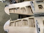
With the lights wrapped up it is time to start the last few items on the list. that includes closing the open holes in the wings. I removed a tiny amount of balsa toward the leading edge of the wing. There was ply beneath the balsa so it could support new panels without me adding any weight. Some additions of scrap balsa will support the sheets of balsa. You can compare/contrast the top and bottom in the attached picture to see what I cut or added. Both wings are now prepared in this way.
IMG_7721.JPG
 

willsonman

Builder Extraordinare
Mentor
So really what's left on the wing?

Obviously the balsa sheeting needs completion. That should not take long and blending in as well. I'll apply spackle to the joints as well as the edges of the pylons to blend those as well.

I need to fabricate fiberglass secondary gear door covers for the inside. Another detail I wish Hangar 9 had included. But it's two more servos, 4 more hinges, and more moulded fiberglass to do it. Not to mention possibly a sequencer for the ARF. I'll use a separate channel on my Horus and add delay. With this part, I'm thinking I'll do the same as my tail gear doors but I'll add a second finishing layer. I'll also try and be more careful with planning and put the glass more on a 45-degree bias for better strength. This part is bound to see more turbulence. After that I can cut the hole for it in the wing, add some hinges and a servo and get the gear installed for exact fitting and cutting.

Maybe I can do all this this week... maybe not, but let's find out.
 

wilmracer

I build things that fly (sometimes)
Mentor
So really what's left on the wing?

Obviously the balsa sheeting needs completion. That should not take long and blending in as well. I'll apply spackle to the joints as well as the edges of the pylons to blend those as well.

I need to fabricate fiberglass secondary gear door covers for the inside. Another detail I wish Hangar 9 had included. But it's two more servos, 4 more hinges, and more moulded fiberglass to do it. Not to mention possibly a sequencer for the ARF. I'll use a separate channel on my Horus and add delay. With this part, I'm thinking I'll do the same as my tail gear doors but I'll add a second finishing layer. I'll also try and be more careful with planning and put the glass more on a 45-degree bias for better strength. This part is bound to see more turbulence. After that I can cut the hole for it in the wing, add some hinges and a servo and get the gear installed for exact fitting and cutting.

Maybe I can do all this this week... maybe not, but let's find out.

Good luck! Those gear doors may be a pain but they will add a TON to the character of the model. I understand why the manufacturer left them off but getting it right will be awesome.
 

willsonman

Builder Extraordinare
Mentor
Oh, I agree. If I had all the time in the world I'd work out a 3D print for it but I just don't at this stage. The complex and subtle curvature on this kind of wing is very problematic. It's a very difficult part to begin with and When I think about how much time it would take to get right... I totally understand more why Horizon did not include this part.

My leg and foot had serious swelling issues yesterday so I was only able to get into the basement for about 30 minutes before I had to elevate again.

I was able to get the balsa sheeting completed. I decided to work from the outer end inward. This would allow be to use a finger underneath to position the piece, should it be needed. Occasionally it was necessary but only to satisfy my own level of precision. TBH, the spackling and sanding would take away any errors from this. Nevertheless, one wing was done, I felt OK, so I did the other wing. I wanted the spackle to have lots of time to dry so I pushed myself to slap on the spackle to dry overnight. You can see I applied it to the pylons and wingtip light cover seams as well. Just a precaution and most of this will be sanded away so very minimal weight penalty for smooth seams.
IMG_7722.JPG IMG_7723.JPG IMG_7724.JPG
 

willsonman

Builder Extraordinare
Mentor
All spackle sanded and no touch ups required.

I had previously observed the curvature of the gear doors in the package. I assembled one retract and drilled out the moulded parts for holes to mount the doors. The aluminum mounts are great but the precision of the door, I found lacking. The door was not centered so I ended up drilling out the holes on the wheel end and re-positioned the door. I used a fine-tipped sharpie to trace around the bolt heads and I'll fill this cavity up with epoxy and re-drill the holes.
IMG_7726.JPG

Next we get to the setup for the fiberglass work. I figured that the curvature wil not exactly match that of the wing and this was the main reason for mocking all of this up. I usually apply a piece of cardstock over the cavity in the wing, then plastic wrap, and then apply glass over this for an easy release. With how bulbous the door is, it makes an impossible transition between the door and the wing. Two things here. The curvature of the door is too steep... like it's been over-curved. The end toward the wheel flares away from the strut as if to give more clearance... but its nearly a full CENTIMETER! Way too much overkill on that. The absolute blessing here is that these gear doors are not fiberglass. They are ABS or polystyrene much like other parts in this kit. So, the plan is to set the oven to 250F and place these on a WOOD sheet and let even heat try to flatten them out. A heat gun is out of the question. The direct heat would for sure warp and destroy anything in my hands. The oven will provide even heat and allow the plastic to flatten out naturally through gravity. It just needs to flatted a bit, not completely. No metal baking sheet for this... again.... even heat.
IMG_7727.JPG