
You are using an out of date browser. It may not display this or other websites correctly.
You should upgrade or use an alternative browser.
You should upgrade or use an alternative browser.
Wooden Bat Bones Frame Build
kah00na
Senior Member
Ok. What's the lip on the lower plate on cad drawing for?
Yeah, I don't know. The original frame's lower plate looks a lot smaller and that is where the camera tray attaches. I'm not sure why it is so large in the CAD picture - it is just the way EdinSimon made it. Also the upside down leg thing is suppose to have the holes lower so it can attach to the side of the rear arm and point up. That is where the FPV transmitter is suppose to attach. David used some upside down landing gear on his so that is what that piece is suppose to be.
brettp2004
New member
This looks really nice. I just got done building my batbone and this looks just as good. You can't even tell it's wood. Great job. Also, for anyone building, instead of putting the KK2 inside the batbone I just left it in the foam case it came in and attached it to the frame with two rubber bands. It is completely protected by foam but can easily be taken out if need be. You can also put the receiver on the front under the rubber bands. This leaves room inside for a power distribution board.
kah00na
Senior Member
This looks really nice. I just got done building my batbone and this looks just as good. You can't even tell it's wood. Great job. Also, for anyone building, instead of putting the KK2 inside the batbone I just left it in the foam case it came in and attached it to the frame with two rubber bands. It is completely protected by foam but can easily be taken out if need be. You can also put the receiver on the front under the rubber bands. This leaves room inside for a power distribution board.
Can you post a picture of what yours looks like?
brettp2004
New member
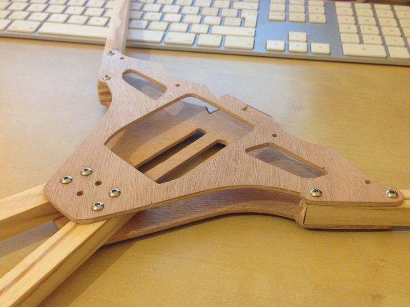
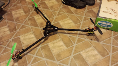
.JPG") Here is a picture of the one I built. This one I actually built for a friend. The booms are the ones from flitetest. The rear booms are 10" and the front ones are I believe 4cm shorter, so about 8.5". I'm building mine in the next couple of days and I'm putting the HK distribution board inside the frame (soldering all the connections was a pain!) so I will mount the KK2 like this one. I also really like your rear motor mounts, I might have to steal the idea. I'm sorry to say but the rear motor mounts I bought from flitetest are a little brittle. I've already broken two, one was from stupidity though.
Here is a picture of the one I built. This one I actually built for a friend. The booms are the ones from flitetest. The rear booms are 10" and the front ones are I believe 4cm shorter, so about 8.5". I'm building mine in the next couple of days and I'm putting the HK distribution board inside the frame (soldering all the connections was a pain!) so I will mount the KK2 like this one. I also really like your rear motor mounts, I might have to steal the idea. I'm sorry to say but the rear motor mounts I bought from flitetest are a little brittle. I've already broken two, one was from stupidity though.View attachment 13054 Here is a picture of the one I built. This one I actually built for a friend. The booms are the ones from flitetest. The rear booms are 10" and the front ones are I believe 4cm shorter, so about 8.5". I'm building mine in the next couple of days and I'm putting the HK distribution board inside the frame (soldering all the connections was a pain!) so I will mount the KK2 like this one. I also really like your rear motor mounts, I might have to steal the idea. I'm sorry to say but the rear motor mounts I bought from flitetest are a little brittle. I've already broken two, one was from stupidity though.
Looks good and I now see what you mean by leaving the KK2 in the packaging (dampening & crash protection = nice)
Yeah, I don't know. The original frame's lower plate looks a lot smaller and that is where the camera tray attaches. I'm not sure why it is so large in the CAD picture - it is just the way EdinSimon made it. Also the upside down leg thing is suppose to have the holes lower so it can attach to the side of the rear arm and point up. That is where the FPV transmitter is suppose to attach. David used some upside down landing gear on his so that is what that piece is suppose to be.
kah00na, I'll check the lower plate again in my 3D CAD Model as it does look big - I presumed the side lugs were more support for a Go-Pro & hadn't realised the sticking up bit on the landing gear is for the AV Gear I'll amend and change the PDF's on my first post.
I too would love to see pictures of anyone else who uses these plan to cut there own - I've still to make one myself using the APM just haven't got around to it yet.
Also like I said before.. If anyone has sugestions they'd like to see just let me know and I can add them.
I'm going to start on the frame tonight, but since I'm having trouble getting my hands on 1/8 inch plywood I will be trying to make them out of 1/8 inch acrylic and cover them with corbonfiber looking vinyl, only because I have some laying around and really want the frame to be black(ish)
kah00na
Senior Member
kah00na, I'll check the lower plate again in my 3D CAD Model as it does look big - I presumed the side lugs were more support for a Go-Pro & hadn't realised the sticking up bit on the landing gear is for the AV Gear I'll amend and change the PDF's on my first post.
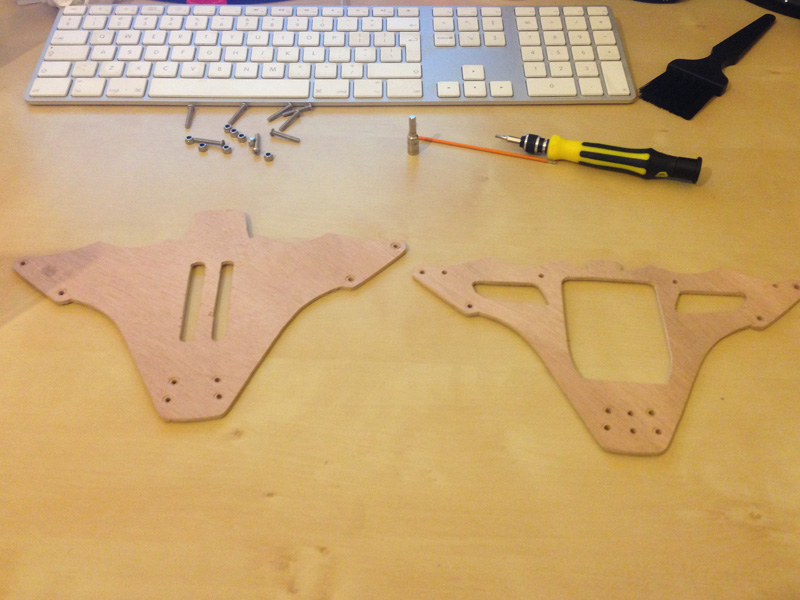
Cool, thanks! I'm re-cutting my plates from the CAD template. Once I get them done, I'll post some pictures of them. I'll probably use the same boom lengths that brettp2004 referenced in his post (The rear booms are 10" and the front ones are I believe 4cm shorter, so about 8.5".) My replacement motor is being shipped but since I have three good motors, I may start this as a tricopter and then convert it to a quadcopter later.
Thought I'd post/hijack my attempt using the CAD templates (which are a life saver!) using 3mm plywood too
Put together...
Just waiting on the electrics now
Mad cutting skills, did you use a jig saw?
epic.engineering
Senior Member
I'm going to post pictures of mine when I get home.. thanks OP for the cad plans
How much does it cost total?
with electronics and wood and so on
My guess is around $300 incl. transmitter. This guess is based on this scrap build http://flitetest.com/articles/tricopter-scratch-build
epic.engineering
Senior Member
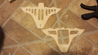
Wood cost me$10. 39 and I had enough to build two frames all landing gear, motor mounts.. just need more booms for the extra frame.. so I'm building one v-tail. And a tri..posting pictures tonight
Mad cutting skills, did you use a jig saw?
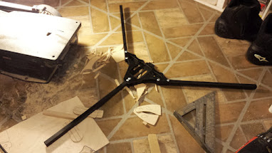
Coping saw, then a lot of filing, probably spent too much time on something I'll destroy the first time I fly it
Don't be hard on yourself! It might last two or three flightsCoping saw, then a lot of filing, probably spent too much time on something I'll destroy the first time I fly it
epic.engineering
Senior Member
Here is a few pictures of mine.. I'll start a new thread so I don't jack this one..lol
New Thread
http://forum.flitetest.com/showthread.php?5515-First-scratch-build-Multi-Rotor-Wooden-Bat-Bone-Tri-and-V-tail-quad
New Thread
http://forum.flitetest.com/showthread.php?5515-First-scratch-build-Multi-Rotor-Wooden-Bat-Bone-Tri-and-V-tail-quad
Last edited:
Similar threads
- Replies
- 16
- Views
- 2K
- Replies
- 4
- Views
- 451