
Tmarter
New member
So, this is going to be a pretty in-depth thread about the Spedix s250 quad, and what I've gathered from my own experiences, what it is now, and plans for what I'll be doing next. I'll do my best to separate it into sections with headers, as it may end up being kind of lengthy. I'll include any and all info on the topics I'll go over, including unexpected problems I ran into, what you should expect, and if you are one of those who has one, maybe it can give you some guidance if you are unsure, or maybe even give you some ideas. I'll post this at the end as well, but if you end up having any questions, comments, opinions, or money ") p) I will gladly accept all of it, and do my best to get back to you ASAP. I didn't see very many resources or builds other than typical reviews, and I like to see a little bit of a variety once in awhile, so this is for anyone that it may apply to.
p) I will gladly accept all of it, and do my best to get back to you ASAP. I didn't see very many resources or builds other than typical reviews, and I like to see a little bit of a variety once in awhile, so this is for anyone that it may apply to.
GENERAL DESIGN, AND WHAT LED TO MY ISSUE
What I thought was going to a be simple flight controller and PDB swap turned into a minor headache. First of all, I love this quad. It has flown great so far, and have flown almost 30 flights with hardly any issues at all, except for the "overly-basic" and limited tuneability of the KK2 in comparison to configuring CC3D with the OpenFlight software suite. I've managed to film a handful of videos, put some on YouTube for some friends, and it's just all around been a lot of fun so far, especially after getting into FPV. This was my first 250 class quad, as I've flown the crap out of the smaller ones, but was a whole different ballgame compared to the Nano QX and Inductrix that I flew around the house (and still do). Eventually I found that there was a handful of things that seemed to be kind of annoying with my setup, and I have thought of ways to improve on it, without sacrificing an arm and a leg or forking up another chunk of cash for another entire model. I'm definitely not rich, but not cheap! If that makes sense, or if it's even possible. Who knows.
To start off, I picked this quad up secondhand, as one of my buddies had originally picked it up from a local hobby shop near us, and lost interest after about a few weeks. It was a BNF version, and I'm not sure why, but apparently it was not exactly the same design as the ARF versions. Not only that, but the option of either a KK2 or a CC3D flight controller makes a total of FOUR different layouts...maybe more if you count the agility frame, Hexacopter frame. Basically everything but the upper and lower frame pieces are the same Sure that only seems obvious, but there were some big differences that weren't as obvious as I would have thought.
Things like the same esc's being used across all models, but some coming with different wiring...different versions of CC3D controllers in both kits and replacement parts on the shelf, some motors with bullet connectors and some that were soldered to the esc...Maybe it was just put together differently as a RTF kit, vs someone buying the ARF solderless "lego" kit. Not bashing anyone's reasoning for buying one, but why assemble it differently, if the end result means the parts will be different, and might I add, original spare parts for the RTF kit not even being available...I mean it's just complicating things, especially for those who might crash it, try to rebuild it, to find out everything was soldered together with wires jammed in bad spots, and no support or resources online. With so many unnecessary variations I can understand why there's only a handful of videos that go into great detail, like Buddy RC. All that being said, the diversity of what kind of 250-300 class multirotor you can get from Spedix is great. Quality is probably solid medium, given some people's motor bells literally flying off of the SunnySky 2204/2300kv motors (NOT 100% Spedix's fault I guess...but at the end of the day, quality control falls on the last person to inspect parts they sell), but the differences in the assembly of the ARF to BNF versions is pretty unnecessary.
So that being said, The BNF is what i had to work with, and I just felt compelled to do a nice in-depth overview on everything in case there's anyone that thinks they might be SOL. Don't worry, you're not!
DIFFERENCES IN ASSEMBLY: BNF VS ARF
BNF versions came with a carbon fiber bottom frame plate with a PDB circuit built into it, and had a matte-like finish on the surface, which was similar to the carbon top frame plate. ESC's were connected by white plastic 3-pin connectors on the PDB, and the flight controller of choice had downward-facing pins for the sets of motor outputs, so it popped right on top of the PDB nice and clean:
View attachment 58970
BNF s250 Bottom Frame Plate w/ Built-In PDB
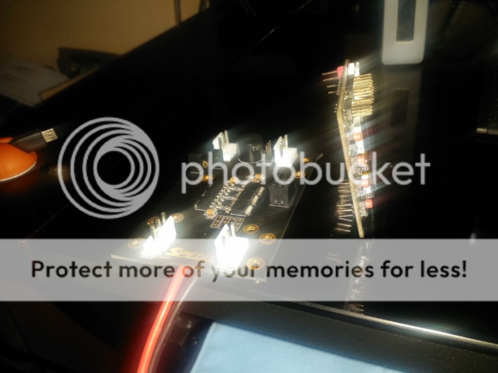
ARF versions came with the typical glossy carbon frame plates, and also came with a separate compact PDB, which either flight controller was mounted on, preferably with either double sided tape... or for a more solid foundation, (and probably more accurate sensor readings) meant going out and buying yourself more standoffs and screws. However, there were no longer those dumb white connectors for the esc's anymore, and instead, you had inputs for a a set of TWO 2mm gold bullet connectors from each esc, for a total of SIX...Which means they used this standalone PDB for the Hex model they released later on...but eventually there came to be a REVISION to this board (NOT THE ONE PICTURED, ran out of data for pics look at my quad as a point of reference, later in the thread), and none of the support was updated to emphasize it! SWEET. The revised version of the board (which I recently installed) now has separate cables and sets of pins for supplying power to auxiliary components or FPV gear, whereas the first board had it soldered on, they changed the orientation of the battery leads with the Deans connector pre-installed, so that instead of being connected on the side, it feeds through the hole in the back so that you can connect it from the back. Giggity.
View attachment 58972
1st version of the ARF s250's PDB
View attachment 58971
Revised PDB
...I wanted a smaller PDB for mine anyways...when my buddy crashed it before I took it off his hands, he apparently flew it into a tree and busted the bottom pdb plate. Interestingly enough, it didn't damage the PDB circuit. It still worked perfectly fine, and still had "most" of the important mounting holes so it could line up...which were the same mounting points as the stardard carbon lower frame plate (hmmmm....???) So...we bought a new carbon plate, dremel'ed off the broken parts around the circuitry and made a nice carbon fiber sammich...which was "kinda" held in by zipties in the corners and this crazy 3m tape that was super strong, and had a thick gel-like adhesive for absorbing impact, which seemed pretty solid...Although, I was later wondering if having the flight controller mounted so a soft surface like that would affect the quad's "snappy-ness", and if it possibly lowered the accuracy of the sensors on the board, as compared to being more fixated directly to the fame...idk...was always a thought running through my head.
After trimming the busted edges of the original PDB
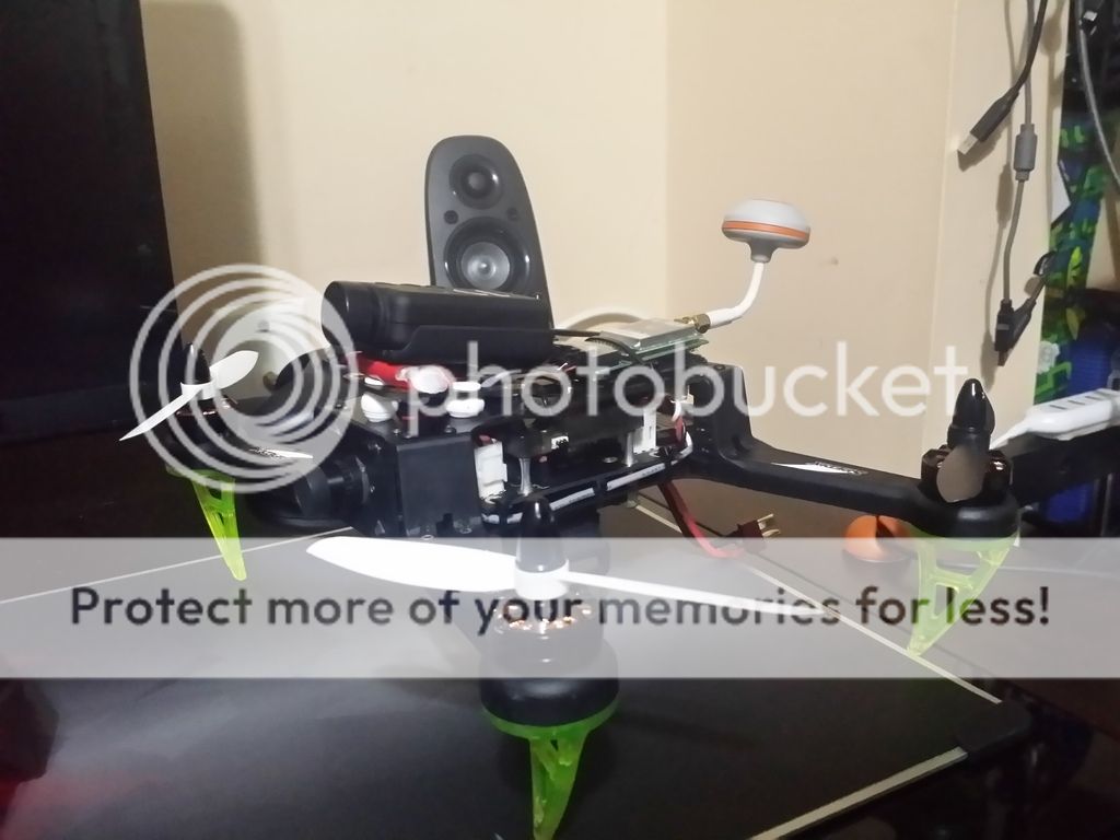
3M double-sided tape and zippy ties galore...but I flew it for about 30 flights and didn't have hardly any issues at all, except for my pet-peeves of it's aesthetic qualities...all rigged-up looking...haha
That being said, I normally prefer not to rig things up if I have the option not to...but truth be true, the struggle is real, and I didn't have an option, nor the money to do it differently! Additionally, when I really got to messing with the PIDs and autolevel settings, I had to take the dang thing apart like 3 or 4 times a day trying obtain more aggressive settings that I was comfortable with...with the positioning of that carbon fiber pdb sammich that was going on, there was no room to get your hands in and play around in the menus...especially when I later added the Mobius and FPV gear, and really wanted things dialed in better as I got more comfortable.
p) I will gladly accept all of it, and do my best to get back to you ASAP. I didn't see very many resources or builds other than typical reviews, and I like to see a little bit of a variety once in awhile, so this is for anyone that it may apply to.GENERAL DESIGN, AND WHAT LED TO MY ISSUE
What I thought was going to a be simple flight controller and PDB swap turned into a minor headache. First of all, I love this quad. It has flown great so far, and have flown almost 30 flights with hardly any issues at all, except for the "overly-basic" and limited tuneability of the KK2 in comparison to configuring CC3D with the OpenFlight software suite. I've managed to film a handful of videos, put some on YouTube for some friends, and it's just all around been a lot of fun so far, especially after getting into FPV. This was my first 250 class quad, as I've flown the crap out of the smaller ones, but was a whole different ballgame compared to the Nano QX and Inductrix that I flew around the house (and still do). Eventually I found that there was a handful of things that seemed to be kind of annoying with my setup, and I have thought of ways to improve on it, without sacrificing an arm and a leg or forking up another chunk of cash for another entire model. I'm definitely not rich, but not cheap! If that makes sense, or if it's even possible. Who knows.
To start off, I picked this quad up secondhand, as one of my buddies had originally picked it up from a local hobby shop near us, and lost interest after about a few weeks. It was a BNF version, and I'm not sure why, but apparently it was not exactly the same design as the ARF versions. Not only that, but the option of either a KK2 or a CC3D flight controller makes a total of FOUR different layouts...maybe more if you count the agility frame, Hexacopter frame. Basically everything but the upper and lower frame pieces are the same Sure that only seems obvious, but there were some big differences that weren't as obvious as I would have thought.
Things like the same esc's being used across all models, but some coming with different wiring...different versions of CC3D controllers in both kits and replacement parts on the shelf, some motors with bullet connectors and some that were soldered to the esc...Maybe it was just put together differently as a RTF kit, vs someone buying the ARF solderless "lego" kit. Not bashing anyone's reasoning for buying one, but why assemble it differently, if the end result means the parts will be different, and might I add, original spare parts for the RTF kit not even being available...I mean it's just complicating things, especially for those who might crash it, try to rebuild it, to find out everything was soldered together with wires jammed in bad spots, and no support or resources online. With so many unnecessary variations I can understand why there's only a handful of videos that go into great detail, like Buddy RC. All that being said, the diversity of what kind of 250-300 class multirotor you can get from Spedix is great. Quality is probably solid medium, given some people's motor bells literally flying off of the SunnySky 2204/2300kv motors (NOT 100% Spedix's fault I guess...but at the end of the day, quality control falls on the last person to inspect parts they sell), but the differences in the assembly of the ARF to BNF versions is pretty unnecessary.
So that being said, The BNF is what i had to work with, and I just felt compelled to do a nice in-depth overview on everything in case there's anyone that thinks they might be SOL. Don't worry, you're not!
DIFFERENCES IN ASSEMBLY: BNF VS ARF
BNF versions came with a carbon fiber bottom frame plate with a PDB circuit built into it, and had a matte-like finish on the surface, which was similar to the carbon top frame plate. ESC's were connected by white plastic 3-pin connectors on the PDB, and the flight controller of choice had downward-facing pins for the sets of motor outputs, so it popped right on top of the PDB nice and clean:
View attachment 58970
BNF s250 Bottom Frame Plate w/ Built-In PDB
ARF versions came with the typical glossy carbon frame plates, and also came with a separate compact PDB, which either flight controller was mounted on, preferably with either double sided tape... or for a more solid foundation, (and probably more accurate sensor readings) meant going out and buying yourself more standoffs and screws. However, there were no longer those dumb white connectors for the esc's anymore, and instead, you had inputs for a a set of TWO 2mm gold bullet connectors from each esc, for a total of SIX...Which means they used this standalone PDB for the Hex model they released later on...but eventually there came to be a REVISION to this board (NOT THE ONE PICTURED, ran out of data for pics look at my quad as a point of reference, later in the thread), and none of the support was updated to emphasize it! SWEET. The revised version of the board (which I recently installed) now has separate cables and sets of pins for supplying power to auxiliary components or FPV gear, whereas the first board had it soldered on, they changed the orientation of the battery leads with the Deans connector pre-installed, so that instead of being connected on the side, it feeds through the hole in the back so that you can connect it from the back. Giggity.
View attachment 58972
1st version of the ARF s250's PDB
View attachment 58971
Revised PDB
...I wanted a smaller PDB for mine anyways...when my buddy crashed it before I took it off his hands, he apparently flew it into a tree and busted the bottom pdb plate. Interestingly enough, it didn't damage the PDB circuit. It still worked perfectly fine, and still had "most" of the important mounting holes so it could line up...which were the same mounting points as the stardard carbon lower frame plate (hmmmm....???) So...we bought a new carbon plate, dremel'ed off the broken parts around the circuitry and made a nice carbon fiber sammich...which was "kinda" held in by zipties in the corners and this crazy 3m tape that was super strong, and had a thick gel-like adhesive for absorbing impact, which seemed pretty solid...Although, I was later wondering if having the flight controller mounted so a soft surface like that would affect the quad's "snappy-ness", and if it possibly lowered the accuracy of the sensors on the board, as compared to being more fixated directly to the fame...idk...was always a thought running through my head.

After trimming the busted edges of the original PDB

3M double-sided tape and zippy ties galore...but I flew it for about 30 flights and didn't have hardly any issues at all, except for my pet-peeves of it's aesthetic qualities...all rigged-up looking...haha
That being said, I normally prefer not to rig things up if I have the option not to...but truth be true, the struggle is real, and I didn't have an option, nor the money to do it differently! Additionally, when I really got to messing with the PIDs and autolevel settings, I had to take the dang thing apart like 3 or 4 times a day trying obtain more aggressive settings that I was comfortable with...with the positioning of that carbon fiber pdb sammich that was going on, there was no room to get your hands in and play around in the menus...especially when I later added the Mobius and FPV gear, and really wanted things dialed in better as I got more comfortable.
CONTINUED
Last edited:


